vsmStudio - GPIO

Introduction
In vsmStudio, General Purpose Interface Inputs and Outputs (GPIOs) can be used to create logic that starts certain processes in accordance with pre-defined triggers.
This chapter covers the configuration of GPIOs.
First Steps
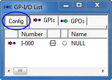
Click on the appropriate button in the main menu bar to open the GPIO list:
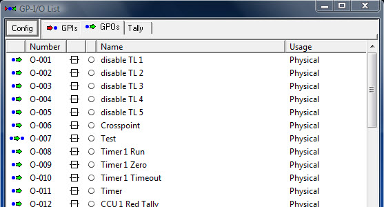
The list shows all existing GPIOs:
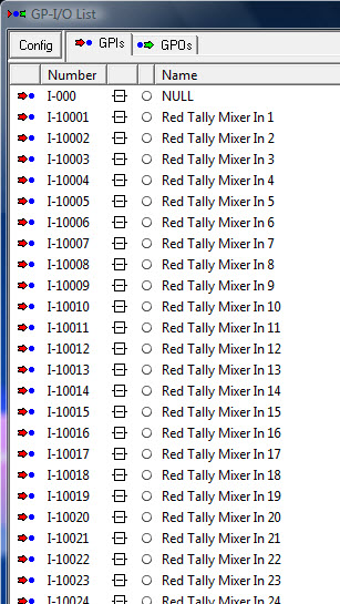
GPI inputs (GPIs) are indicated with a red arrow. GPI outputs (GPOs) are located in a separate tab and marked by a green arrow. The difference between a GPI and a GPO is that a GPI does not contain a logic, but merely serves as trigger for a GPO. GPIs are triggered by a device or something similar. A GPO, in turn, can contain a logic that activates it. It can also serve as trigger.
Editing the GPIO List
New GPI Group
To improve overview, GPIO groups can be created. These can be created and edited in the Config tab. Select Add to create a new group. It will be displayed as a tab in the GPIO List.
|
|
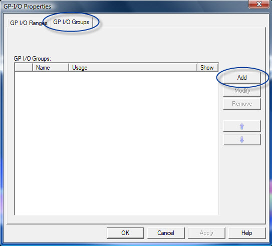
To create a group, enter a name and, if necessary, a purpose in the field Usage. Show GPIs in this group also in the GPI or GPO Groups is checked by default. If the checkmark is removed, the GPIOs can only be viewed in this group. If it is not removed, they can be viewed in the overview.
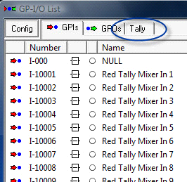
 Creating new GPIO groups |
New tab in GPIO list |
Select Modify in the GPIO Properties to edit a selected group. Press Remove to delete it or use the arrow buttons to sort the groups.
New GPI Range
To improve overview, it is possible to set up GPIO ranges. In these, numbers can be assigned to certain GPIO groups, for instance the numbers 1 to 64 for physical GPIOs.
To create a new range, select Add.
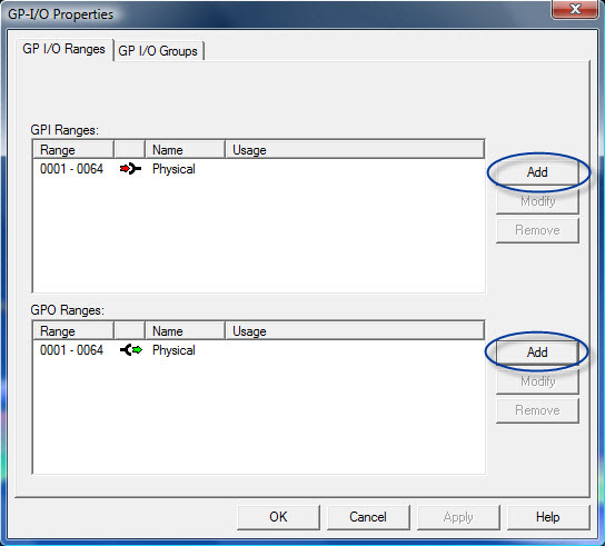
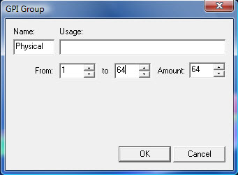
In the newly opened window, enter a name and, if necessary, a purpose for the GPIO. Next, define the GPIO range. If, for higher numbers, only the number of the first GPIO and the total amount of GPIOs is known, the system automatically calculates the last number used in this range using Amount.
To edit or delete a created range, select Modify or Remove, respectively.
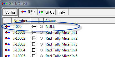
The name of the range is shown at the appropriate GPIOs using the GPIO list.
The system automatically creates the GPI NULL when a new configuration is first opened. If the GPI NULL is dragged into a GPO but not linked, this GPO is set to logical High if the configuration is opened.
New GPIO
To create a new GPIO, right-click into the GPIO list.

Enter name and number for the GPIO in the window, GPIO-Properties.
|
Iterator |
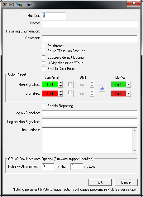

Since the name field features an iterator, multiple continuously counted GPIOs can be created using curly brackets (also see vsmStudio Application Note 020 Using Iterators). The field Comment offers space for comments.
If a GPIO should be logical High at the start of a configuration, the box in front of Set to "True" on Startup must be checked. However, this only works for GPOs without logic that merely execute another application or function, for example controlling another GPO.
Alarm Settings
All other settings refer to the alarm management.
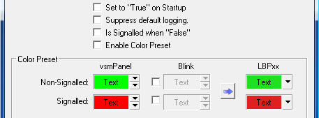
By checking Suppress default logging, logging of logfiles (see Folder LogFiles) can be suppressed for this GPIO. The function Is Signalled when "False" turns the alarm logic around without requiring a change of the GPIO logic. A checkmark before Enable Color Preset enables the editing of colors for the alarm management.
Scheduler Settings
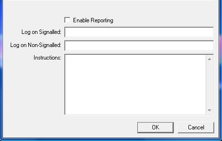
If Enable Reporting is checked, a new channel is created in the scheduler. This channel is shown as Reporting with the text that was entered under Instructions in the scheduler.
GPIOs in the GPIO List
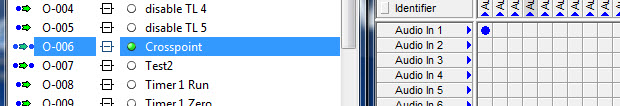
All existing GPIOs are shown in the GPIO list. The green dot shows that this GPIO is active. A second, blue dot indicates that this GPO is executing a logic if it is active.
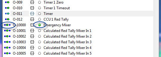
Moreover, the numbers and the name of the GPIO are shown in the GPIO list. To open the GPIO Edit, double-click onto a GPIO.
Here, the connections of the GPIO can be viewed and edited, if required. By right-clicking, the following window opens:
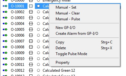
In this window, the selected GPIO can be manually activated (Set), deactivated (Clear) or create a short pulse signal (Pulse). Further, new GPIOs can be set-up and alarms can be created from GPIOs. Moreover, it is also possible to delete the selected GPIO, put the GPIOs into a toggle pulse mode or to open the properties window.
Copying GPIOs
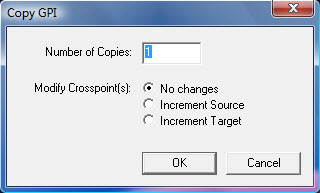
In the window that opens following a right-click onto a GPIO, the selected GPIO can be copied.
Next, define how often the GPIO should be copied. The functions Increment Source and Increment Target are used to copy crosspoint-dependent GPIOs. The crosspoint logic of this GPIO therefore counts either the sources or targets if the relevant function is checked. This way, a continuous series of crosspoint-dependent GPIOs can be copied.
New GPIO Logic
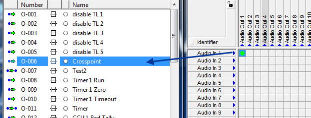
A GPIO can contain a logic if it is set to High at the point when this logic becomes true. To create a GPIO logic, select a GPIO or a crosspoint and drag and drop it into the relevant GPO in the GPIO list.
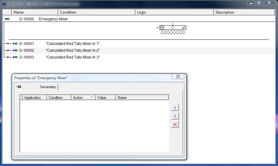
GPIO Edit Window
The name, here Test, and the GPO's trigger, here a GPI, a GPO, and a crosspoint, can be viewed in the GPIO Edit window in the top left under Name. The green arrow in front of the GPO's name indicates that the GPIO is a GPO.
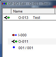
Name and trigger of the GPO
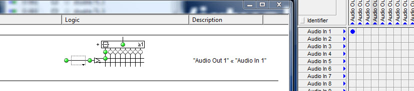
The GPO logic is shown in the center of the edit window. The names of triggers are shown under Description.
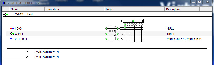
Logic and trigger of the GPO
The listed entry on bottom left of the window indicates what is affected and triggered by this GPO. In the example beloww it is the GPO "Crosspoint".

Boolean Logic
The GPIO logic is created according to the Boolean Algebra. This means that the connection arranged in the square above must be true in order to activate this GPO. In turn, the connection arranged below must be false. A situation in which two connections lay side-by-side is called an Or-condition. In this scenario, the GPO logic is triggered by one trigger or the other. A situation where the connections are linked with each other is called an And-condition. This means that the GPO event will only become active if both triggers are true.
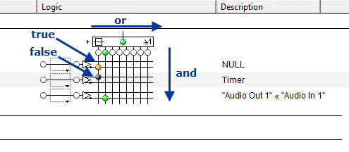
GPO logic
This concept is exemplified in the screenshot above: The opened GPO will become active as soon as the GPO Timer is active and the GPI NULL is inactive, or the crosspoint Audio Out 1 < Audio In 1 is set. The differently coloured connections hereby indicate the following: The orange-coloured dot indicates that the connection is true, but that the execution of the logic is prevented by the And-connection with the other trigger (which is false). A black dot indicates that the trigger is turned Clear. A green dot indicates that the trigger is Set, and that the logic is being executed.
Secondary Commands for GPIOs
When a GPIO is opened, a property box will open in addition to the Edit window, in which secondary commands can be entered.
Crosspoint as Secondary GPIO Command
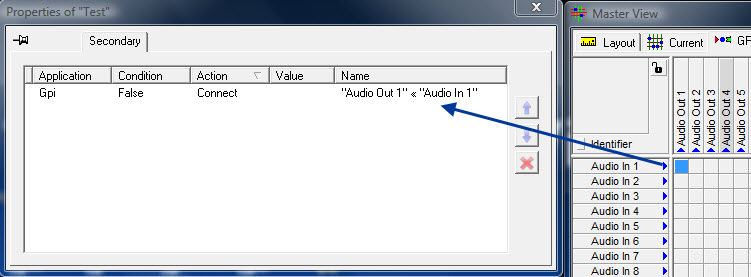
Crosspoint as secondary GPI command
It is, for example, possible to drag-and-drop a crosspoint from the GPI view of the master matrix (see GPI View) into this window, for which various functions can be set-up.
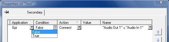
Conditions for a secondary command
In the property window, the Condition as well as the Action that is to be executed if the condition becomes true or false can be defined. An action can, for example, be the connecting or toggling of a crosspoint.
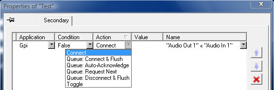
Action of the secondary command
Gadget as Secondary GPIO Command
It is also possible to drag a gadget from the gadget tree (see Gadget Tree) into the secondary command window.
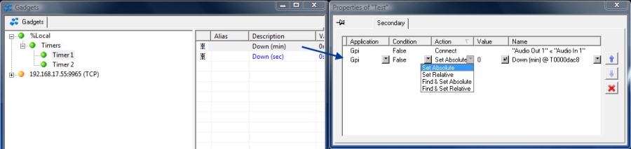
Gadget as secondary GPI command
In this case, a value can be entered in addition to Condition and Action which will cause the GPI to become active as soon as this gadget value is reached. The order of secondary commands can be changed with the blue arrows on the right side of the window. Use the red cross to delete them.
Tally GPOs
If a GPO is dragged onto a signal, a tally is created for this signal (see Tally Management).
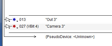
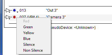
The desired tally color can be defined using the arrow beside the tally symbol. The greyed-out color – red in the screenshot below – is already assigned. Since each color can only be used once, it can no longer be selected.
Crosspoint-GPO-Connection
Triggering a Crosspoint through a GPO
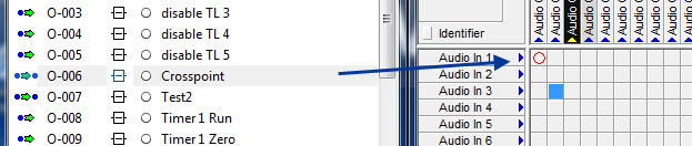
A GPO can be triggered with a crosspoint. To do so, drag the relevant crosspoint from the GPI view of the master matrix into a GPO.
If this crosspoint is set, the GPO becomes active (also see Connection of a GPO with a Crosspoint):
Setting a Crosspoint through a GPO
In turn, it is also possible to drag a GPO onto a crosspoint (in the GPI view of the master matrix) so that the crosspoint is set once the GPO is activated.
This allows, for example, the setting of two crosspoints simultaneously through activating a GPO: If, for example, the crosspoint Audio Out 1 > Audio In 1 is connected with the GPO Crosspoint and this GPO is connected with the crosspoint Audio Out 2 > Audio In 2, setting the crosspoint Audio Out 1 > Audio In 1 activates the GPO, which will also automatically set the second crosspoint.
Crosspoint set using a GPO
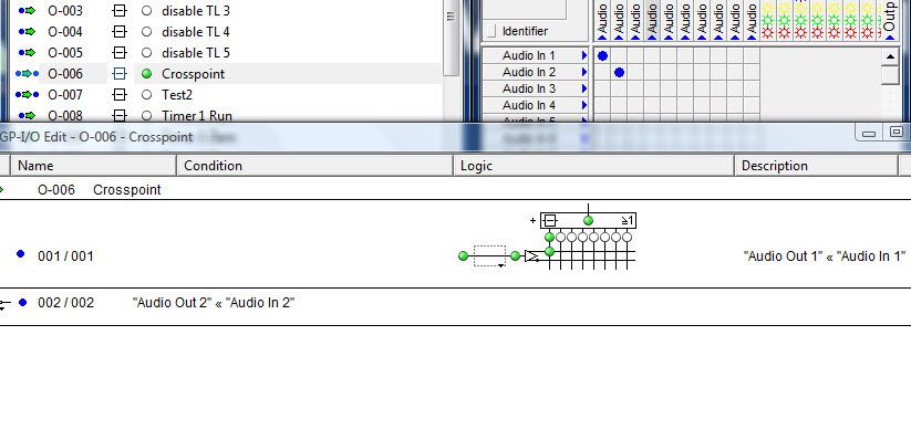
Connection of two crosspoints via GPO
GPIOs on Control Panels
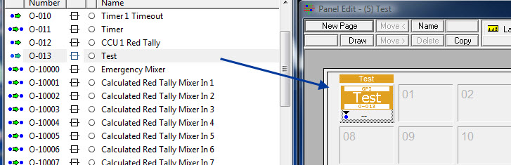
Placing a GPO on a control panel
In the GPIO window, it is indicated whether a GPIO is used on a control panel.
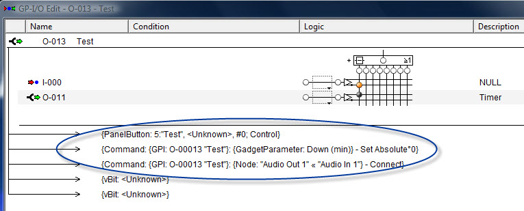
Display in the GPO edit window
The information that the GPO is being used on a control panel is shown in the relevant GPO's Edit window with ID (5) and name (Test) of the panel. Secondary commands of the GPO are listed here as well – in the screenshot above, the crosspoint Audio Out 1 > Audio In 1 and a gadget parameter. Moreover, system-specific vBit entries are shown here as well, which should be neglected.
GPIO Status
To open the GPIO status display, select the corresponding symbol in the main menu bar.

All GPIOs are shown in this view and can be activated or deactivated there.
Under the tab GP-Outputs, the GPOs are displayed as dots. Green dots indicate that these GPOs are active.
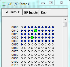
GPO state
The same applies to the two tabs GP-Inputs and Both, in which GPIs and GPIOs are displayed.
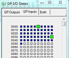
GPI state
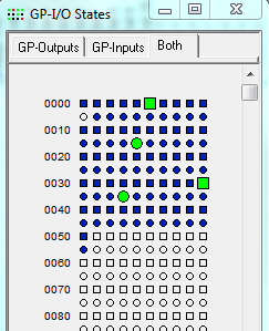
GPIO state