vsmStudio - Layers

Introduction
Layers are core of any VSM configuration and the basis for the configuration of Signal Paths. Layers can be represented in Matrix views. Various Layer types and attributes are available for specific tasks. The general Layer type may represent a physical router hardware that is connected to the system, but a Layer can also represent a fictive matrix that allows logical connections. The specific Layer type Network Layer is dedicated for Network applications and comes with respective features and settings. Another Layer type can also be assigned and controlled by external controllers.
Please note that "Blind" Signal Path must be created on each router layer, so that e.g. Tie-line management will work properly. Depending on the type of device or protocol, the physical Blind Signal may be a dedicated Disconnect source or Black for Video and Mute on Audio layers. Without a Blind Signal, unused Tie-lines cannot be freed, or their status reported properly.
Overview of the Layers Window within Matrix Properties
- Open the Matrix Properties window (1) by click on the respective icon on the vsmStudio top toolbar.
- Select Layers from the menu list to the left (2).
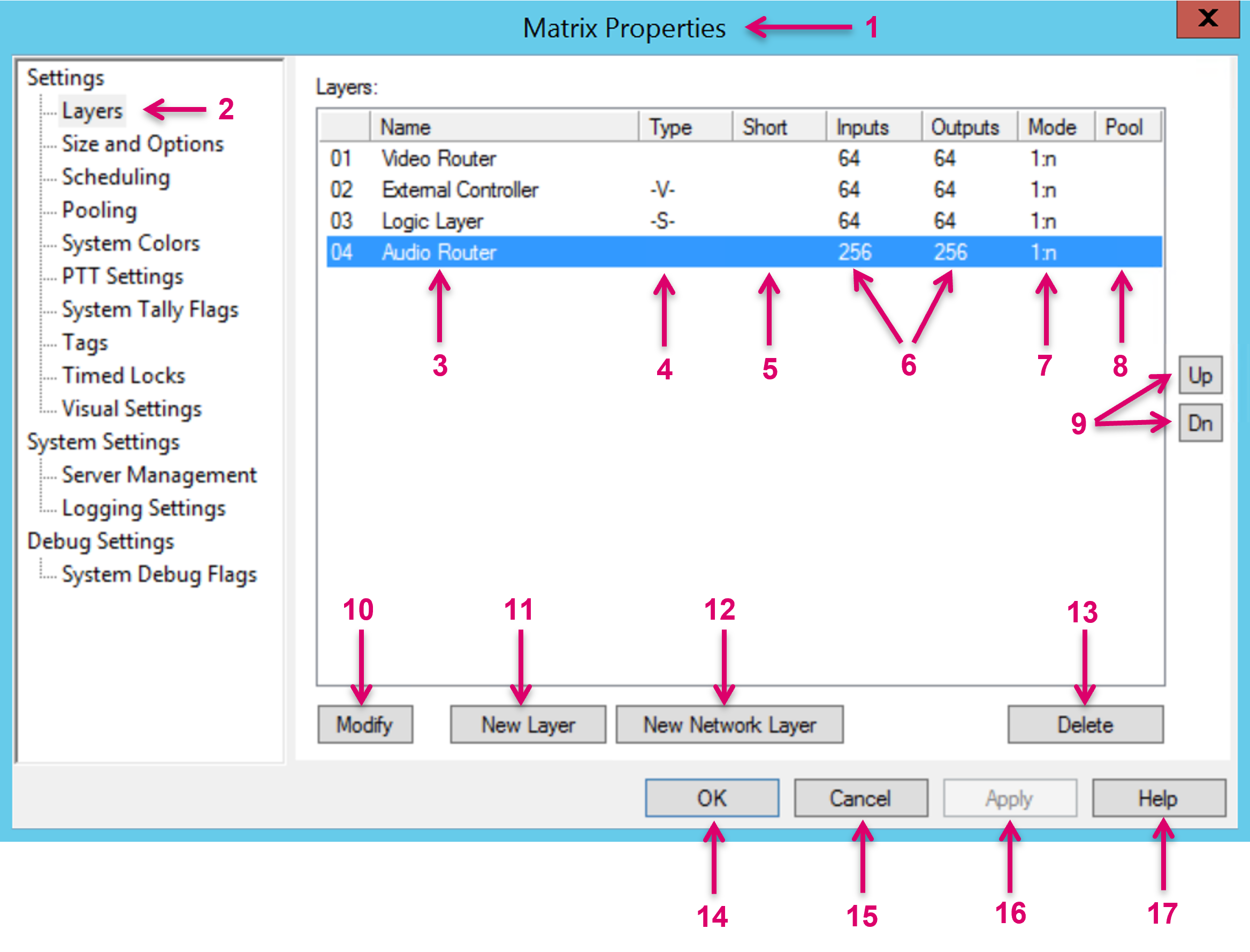
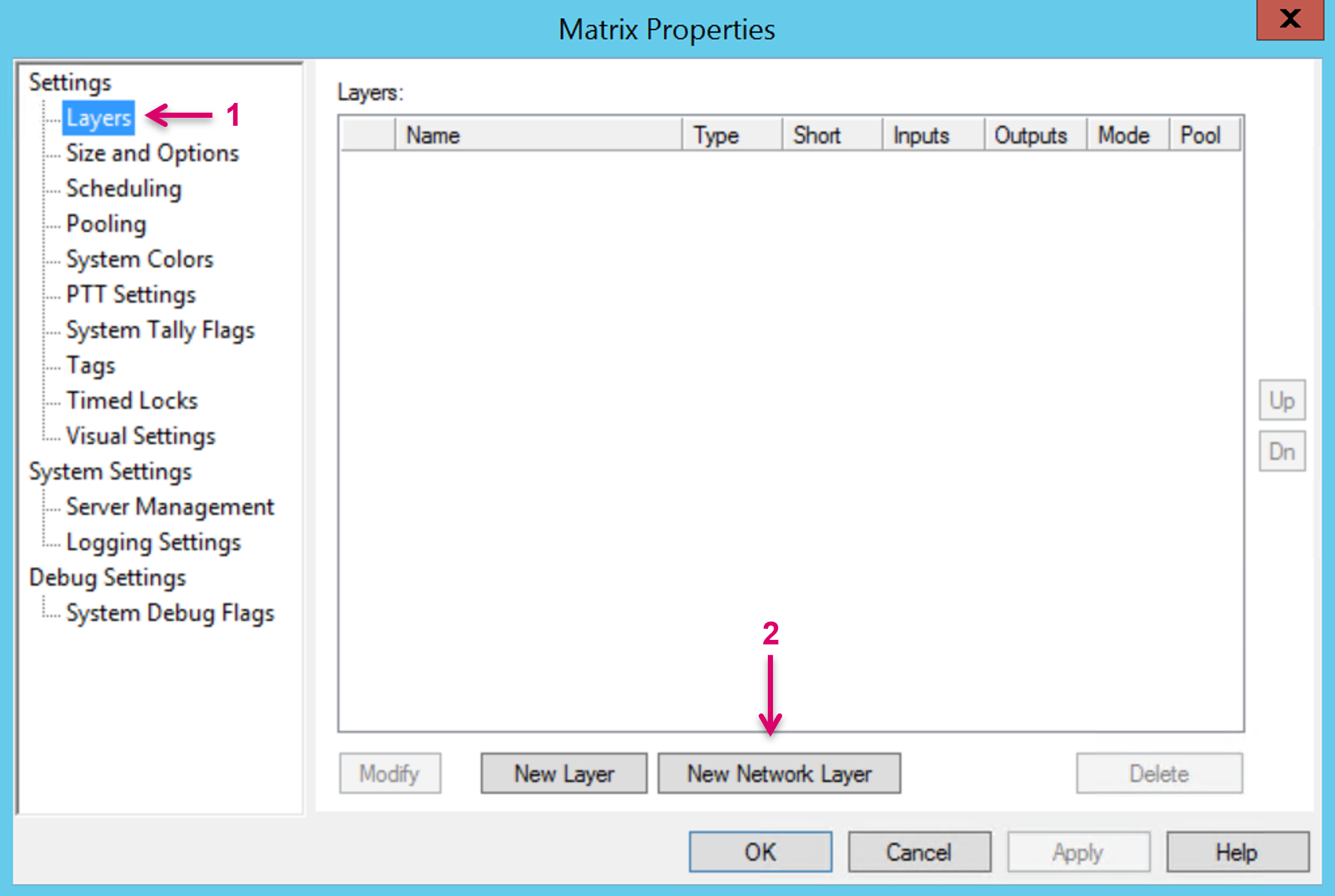
Matrix Properties: The Main section that contains also the Layers window.
1 - Layers: The Layers window gives access to all Layer related settings.
2 - Column Name: Configured Layers displayed by name.
3 - Column Type: Configured Layers displayed by type.
4 - Column Short: Configured Layers displayed by optional short name.
5 - Column Inputs and “Outputs”: Configured Layers displayed by their number of In- and Outputs.
6 - Column Mode: Configured Layers displayed by their Switching mode.
7 - Column Pool: Configured Layers displayed by their optional Pool assignment.
8 - Up and Down: Highlighted Layer can be moved in the listed order. This will also affect the order of tabs in the Matrix view.
9 - Modify: Modify the settings of an existing, highlighted Layer.
10 - New Layer: Create a new Layer.
11 - New Network Layer: Create a new Network Layer.
12 - Delete: Delete an existing, highlighted Layer.
13 - OK: Confirm and end the configuration and close the Matrix Properties window.
14 - Cancel: Cancel and end the configuration and close the Matrix Properties window.
15 - Apply: Not applicable for the Layers window.
16 - Help: Future option currently not assigned.
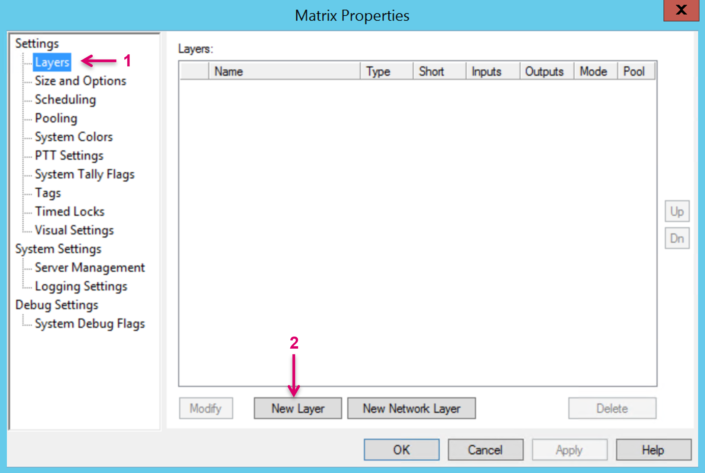
Create a New Layer
For any Layer type other than a Network Layer, go to the Layers window (1) and select New Layer (2).
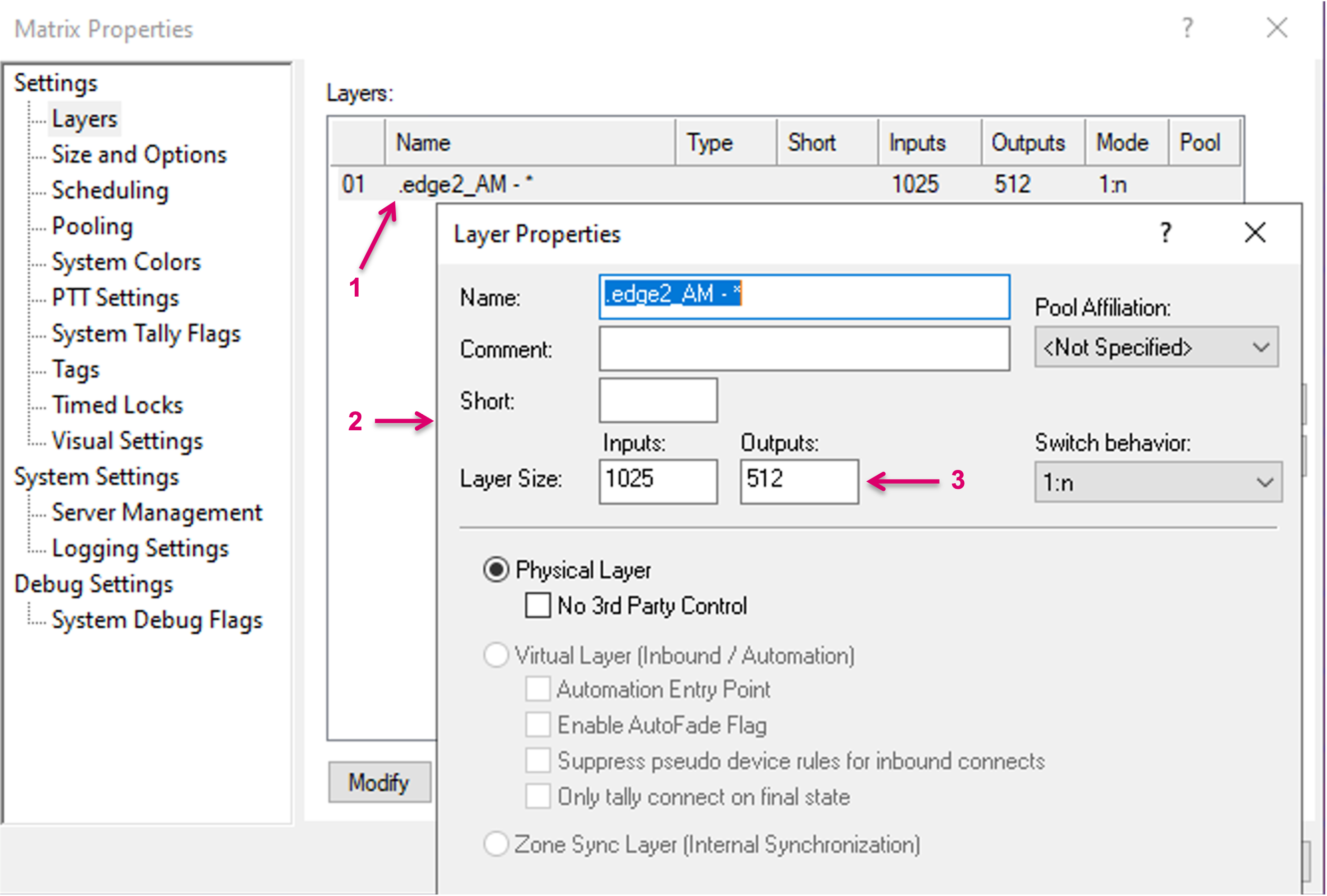
Layer Properties
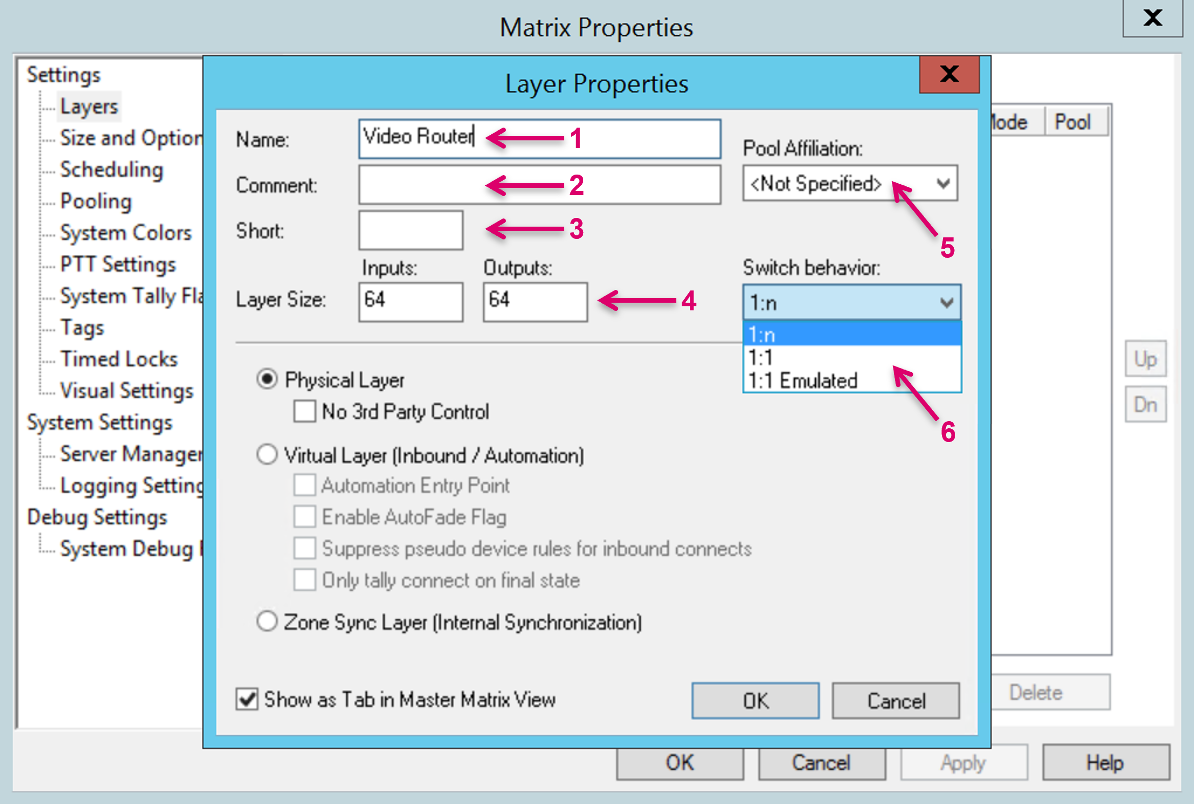
1 - Assign a unique and descriptive Name for the new Layer.
2 - Add an optional descriptive Comment.
3 - Add an optional Short Name.
4 - Define the Layer Size by number of Inputs and Outputs.
5 - If the Pooling feature is used within the system configuration, the new Layer can be assigned respectively via the Pool Affiliation drop-down menu.
6 - Select the desired Switch behavior from the drop-down menu.
The following Switch behaviors can be defined:
- 1:n: The router allows the connection of one source to multiple destinations.
- 1:1: The router allows one connection per source (typical for RS-422 routers).
1:1 Emulated: While the actual router allows the connection from one source to multiple destinations (1:n), the switch behavior will be like a 1:1 router.

For the 1:1 and 1:1 Emulated definitions, a Signal Path configured as blind signal on this layer is mandatory.
The switch behavior of a Virtual Layer must always be 1:n. The actual switching behavior depends on the assigned Signal Paths and their original Layer settings.
Select Layer Type
Select Physical Layer if you want to create a representation of a physical router.
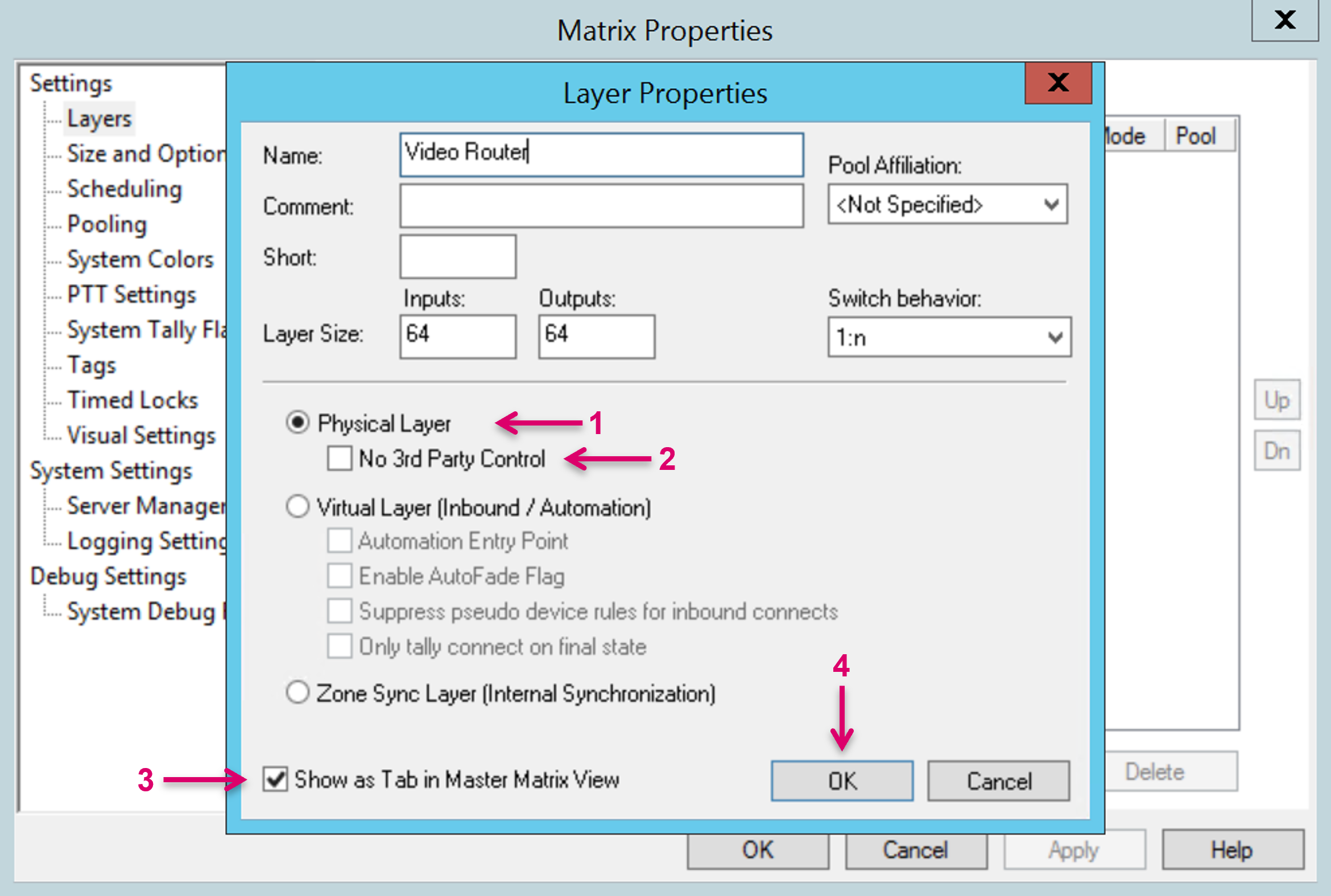
- Select Physical Layer (1) if you want to create a representation of a physical router.
- In addition, select No 3rd Party Control (2) if VSM is supposed to be the only controlling instance, and no other control or automation systems or any other device from the manufacturer is intended to directly control the terminal equipment in parallel. This attribute affects specifically the handling of crosspoints that include Virtual Signals. With this attribute set, Virtual Signal crosspoints will remain in place and not be dropped, even if an external controller triggers a direct physical crosspoint.
- Choose if the new Layer should Show as Tab in Master matrix View (3). By default, this box is checked.
- Confirm and finish the Layer setup with OK (4).
Select Virtual Layer (Inbound / Automation) if you want to create a Layer that can be controlled from an external controller.

- Select Virtual Layer (Inbound / Automation) (1) if you want to create a Layer that can be controlled from an external controller. A Virtual Layer, or vLayer, can be freely assigned with selected Signal Path resources that are configured on any other Layer within the system. This feature may be used by automation systems that need to interface to resources from various hardware.
- The attribute Automation Entry Point (2) is checked in specific system constellations and in combination with connected automation systems.
- When receiving a switch from an automation system, the attribute Enable AutoFade Flag (3) prompts a fade out of the current source and a fade into the new source. This setting is specific and only be used in combination with the AutoFader module.
- If external routing commands should not trigger Pseudo device rules, check the attribute Suppress pseudo device rules for inbound connects (4). Due to the CrossPointCentric routing behavior, triggering a route may result in a confirmed “desired” crosspoint state before the connection can effectively be made.
- The attribute Only tally connect on final state (5) makes sure the crosspoint is first confirmed to the external controller after the crosspoint is complete and finally confirmed within VSM.
- Choose if the new Layer should Show as Tab in Master matrix View (6). By default, this box is checked.
Confirm and finish the Layer setup with OK (7).
Supported inbound protocols for external matrix control are ProBel sw-P-08 and Quartz Native-1.
Select Zone Sync Layer (Internal Synchronization) to create a Layer that does not relate to any physical resources or external device state.
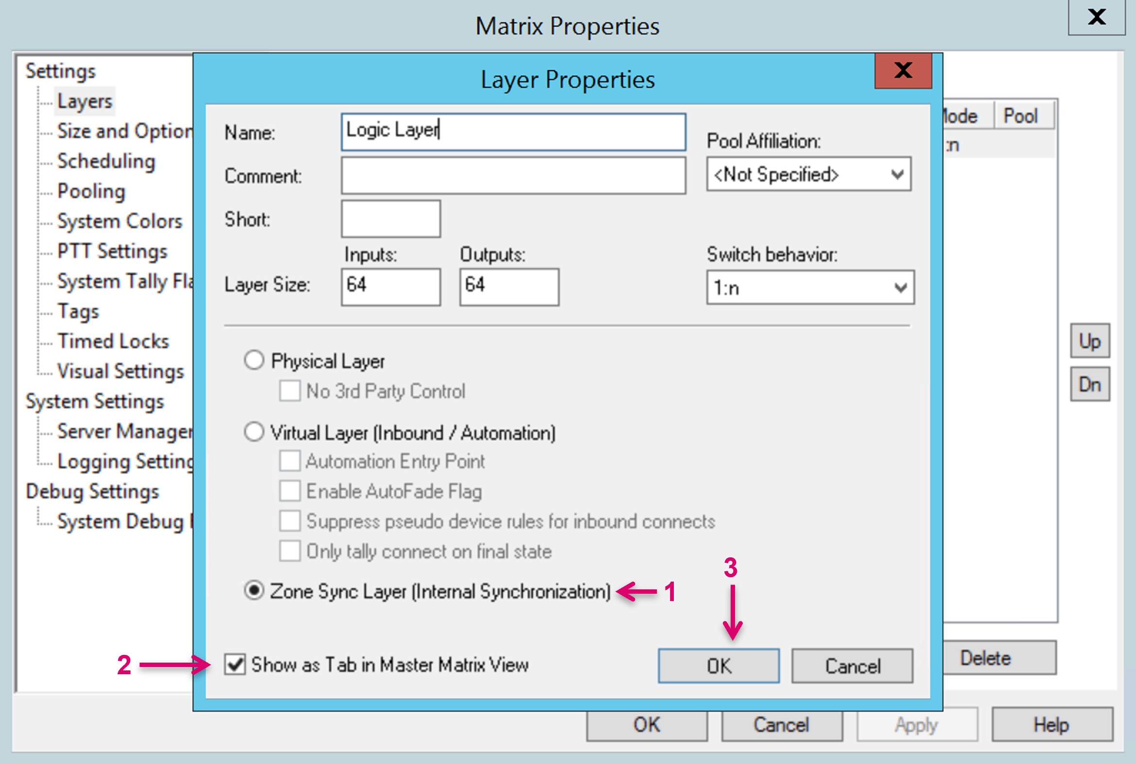
- By choosing the Layer type Zone Sync Layer (Internal Synchronization) (1) it is possible to create a Layer that does not relate to any physical resources or external device state. Crosspoints that are set between Sources and Targets on this Layer type are reflected system internal and their current state is synced across the VSM Server Cluster.
- Choose if the new Layer should Show as Tab in Master matrix View (2). By default, this box is checked.
- Confirm and finish the Layer setup with OK (3).
Create a New Network Layer
Network Layers are the basis for all Signal Paths that represent Network resources. Network Video and Metadata (ANC) essences should always share the same Layer while Network Audio should be represented as a separate Layer. To create a Network Layer, go to the Layers window (1) and select "New Network Layer" (2).
Networking Layer Properties
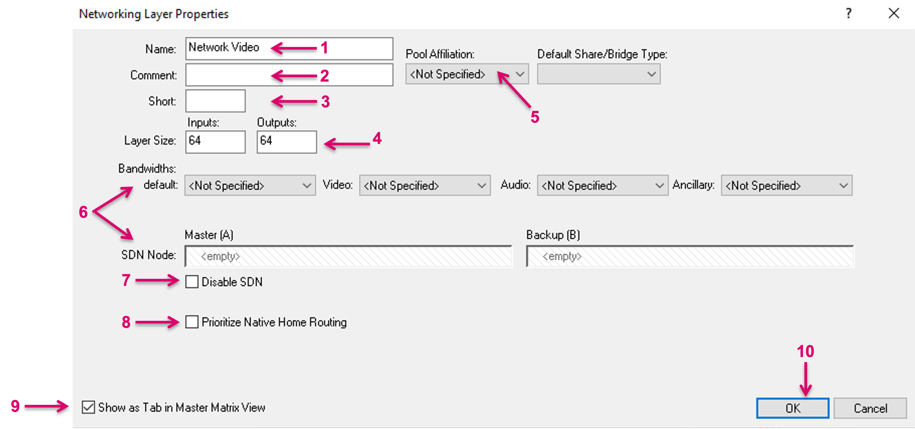
1 - Assign a unique and descriptive Name for the new Network Layer.
2 - Add an optional descriptive Comment.
3 - Add an optional Short Name.
4 - Define the Layer Size by number of Inputs and Outputs.
5 - If the Pooling feature is used within the system configuration, the new Layer can be assigned respectively via the Pool Affiliation drop-down menu.
6 - Specific to an SDN environment are the settings under Bandwidth and SDN Node. For further information please refer to the specific documentation, that can be found here.
7 - Checking the option Disable SDN has the effect that feedback from the SDN controller will be ignored by vsmStudio. Please note that messages towards the SDN controller may still be sent.
8 - The option Prioritize Native Home Routing relates to the communication between vsmStudio and a HOME system (see Note below).
9 - Choose if the new Layer should Show as Tab in Master Matrix View. By default, this box is checked.
10 - Confirm and finish the Layer setup with OK.
The option Prioritize Native Home Routing is effectively a selector for which routing method is used, and which messages are sent accordingly, via the HOME API. It is advised to have this box checked, whenever the system includes a HOME system with enabled Splice service. If the Splice Service in HOME is disabled, the commands set with Prioritize Native HOME Routing enabled will have no effect, so the option may be unchecked. In future versions the option, to manually select Prioritize Native Home Routing being enabled or disabled, may be removed.
System assisted Layer Creation for HOME resources
Specific for the HOME API interface and the, so called, HOME Internal Matrix resources, vsmStudio provides a system assisted configuration method. This method allows the system to create Layers, as well as the related Signal Path resources in a background process.
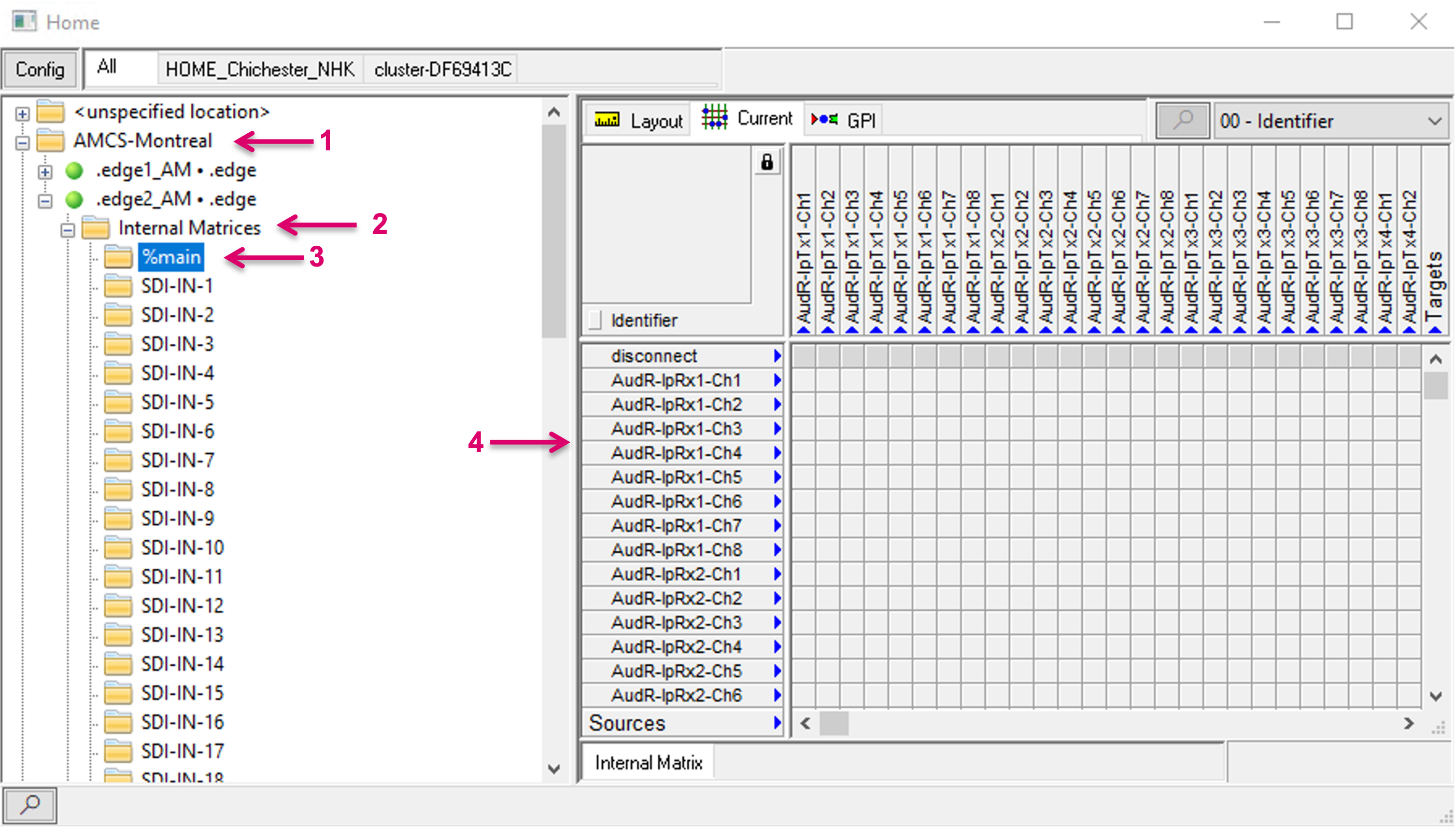
Where applicable, HOME Internal Matrices are exposed via the HOME API and will be listed per Location/HOME Device (1) in the HOME API view. To create a Layer representation including Signal Paths, open the top node of a HOME Device, navigate to Internal Matrices (2) and the respective Internal Matrix. Currently only Audio matrices are available and exposed, and the layer ID of the main Audio matrix is labeled “%main” (3). By selecting an Internal Matrix layer, all Source and Target resources of this layer are also shown in a Matrix overview in the right section of the view (4). These Sources and Targets only reflect the available device resources but do not provide full VSM Signal Path functionality. In this presented form, they cannot be used for any further configuration within the system, e.g., Panel button assignments.
Although it is possible to set xpoints on the physical device immediately, after selecting the “Current” tab, unlocking the Matrix view and clicking in there, there is currently no xpoint feedback in form of blue dots shown in this view.
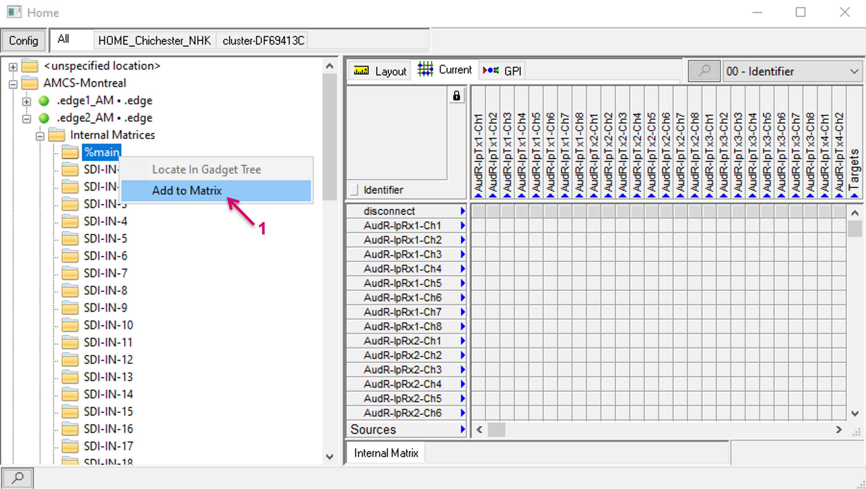
To create a Layer representation including all Signal paths in vsmStudio, right-click on the respective Matrix folder and select Add to Matrix (1).
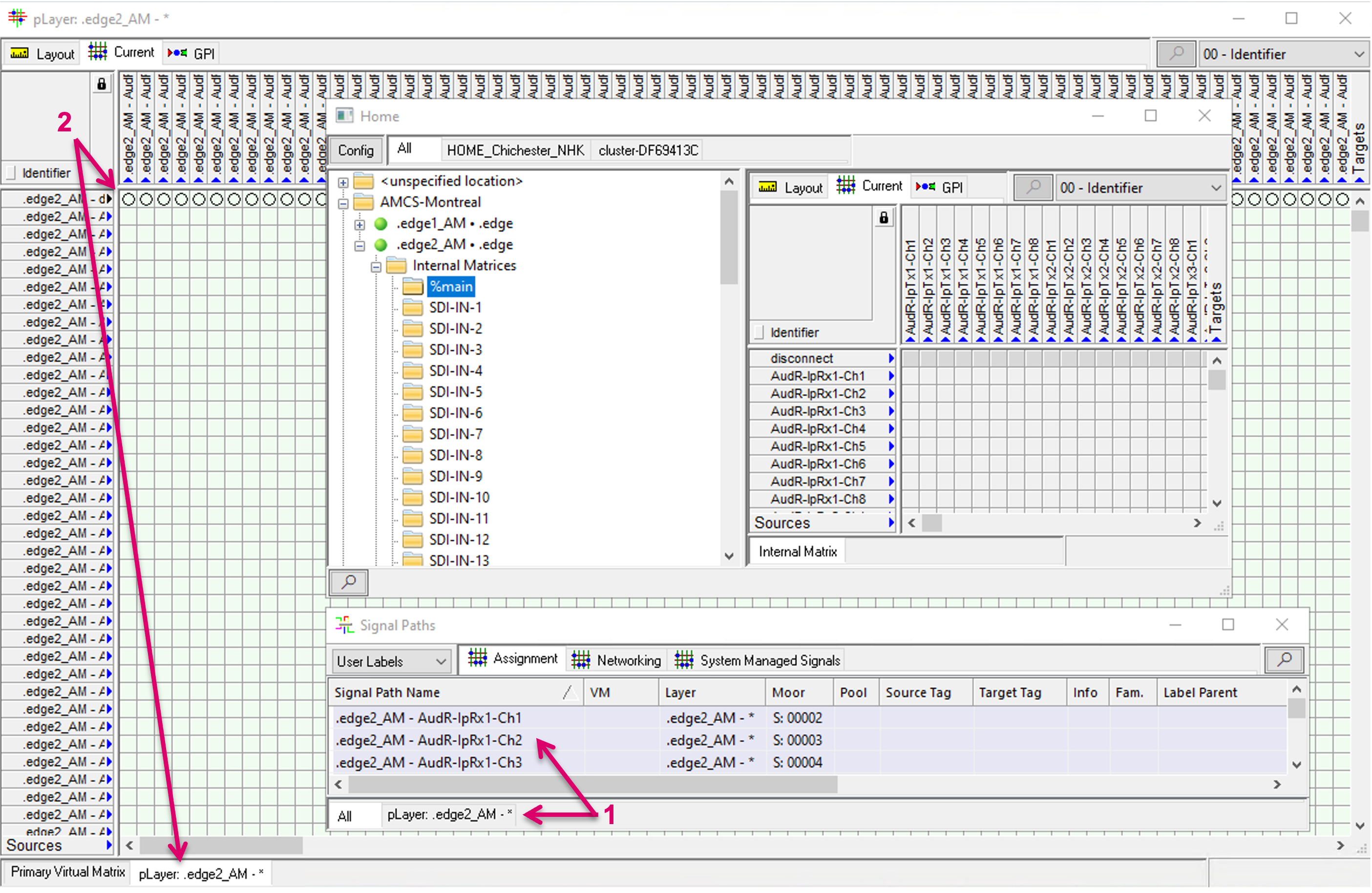
The system then creates the respective Layer, including Signalpaths, in a background process. The respective Layer, as well as related Signalpaths are displayed and accessible for any further usage in Signal Paths list (1) and Matrix view (2), etc.
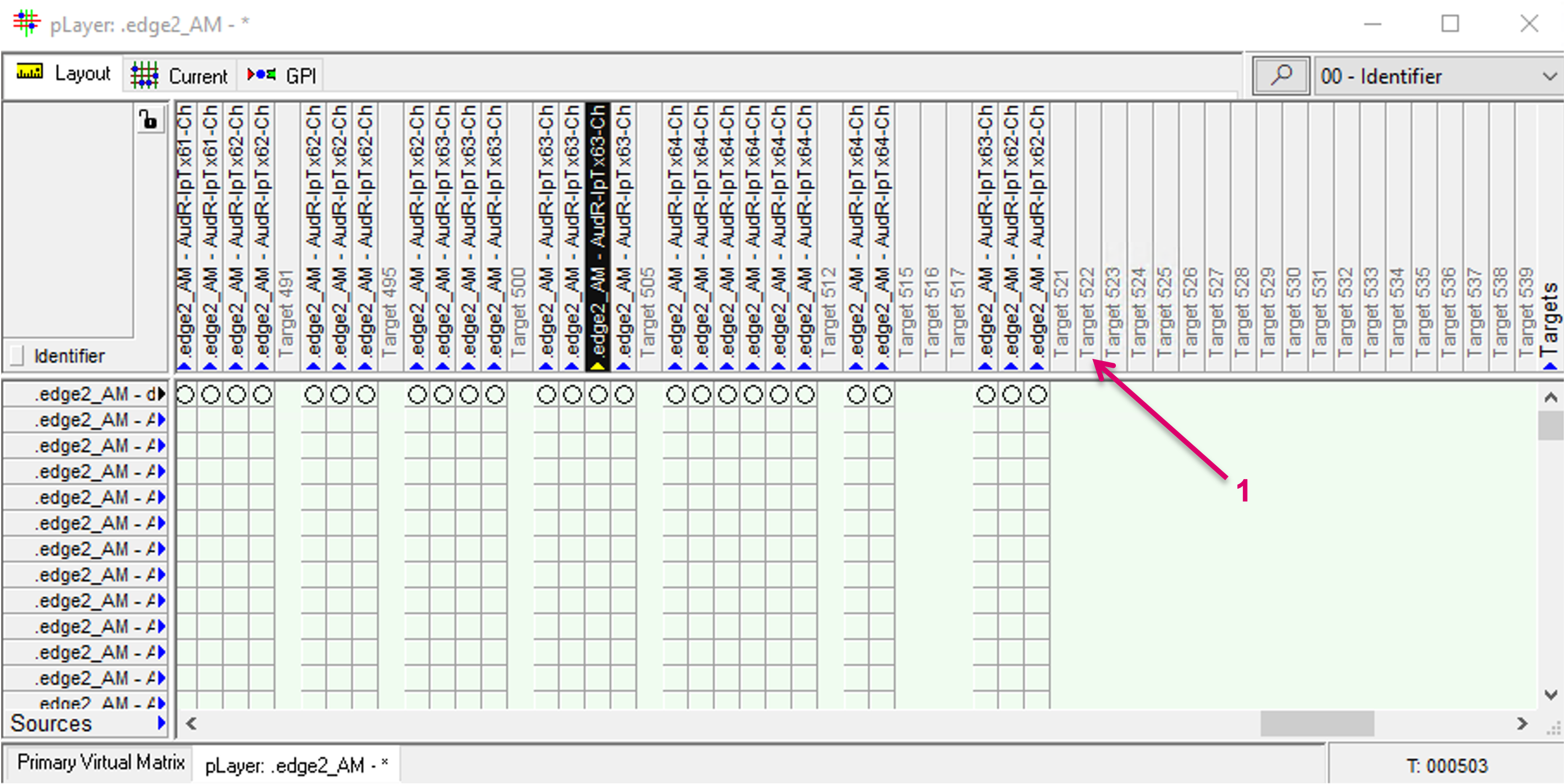
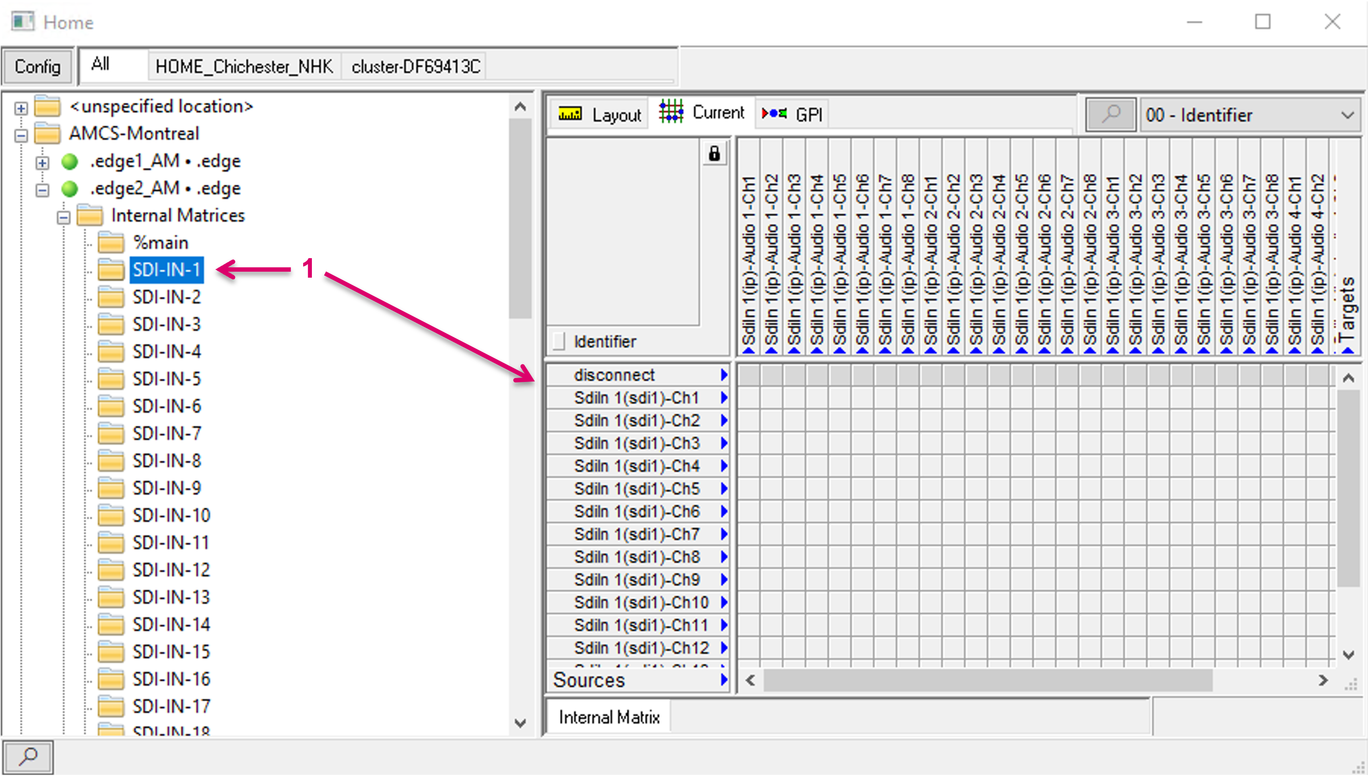
Some HOME devices may provide more matrices than one, e.g., .edge provides a separate Audio routing matrix for each SDI In and Out (1). The workflow to create these Layers follows the same process as described above.
Properties of the system created Layers (1) can still be accessed and modified, if required, after creation (2). When created, the Layer size fits exactly the number of available Sources and Targets. But different to Signal Paths, that were assigned to manually created Layers with static defined protocol ID, the Signals on system-created Layers, have no association to a specific number on this Layer. This allows to move Signal Paths to different positions on the matrix, e.g., to sort them in different order or blocks for organizational reasons.
In order to move a Signal on the matrix, the respective target position must be free. Therefore, it will be required to manually increase the number of Inputs and/or Outputs accordingly (3).
Afterwards Signals can be moved, one by one or multiple at a time, to different (free) positions on the Matrix view (1).