Interface - Arista CVX controlled Media-Network
Introduction
VSM on top of an Arista CVX administrated Network switch topology, provides a full SDN routing solution for deterministic media stream routing in the network. The interface between VSM and CVX is based on a Sender/Receiver concept, means the focus of the broadcast controller is on requesting routes from end to end while all network internal processes including pathfinding within the network is handled by CVX.

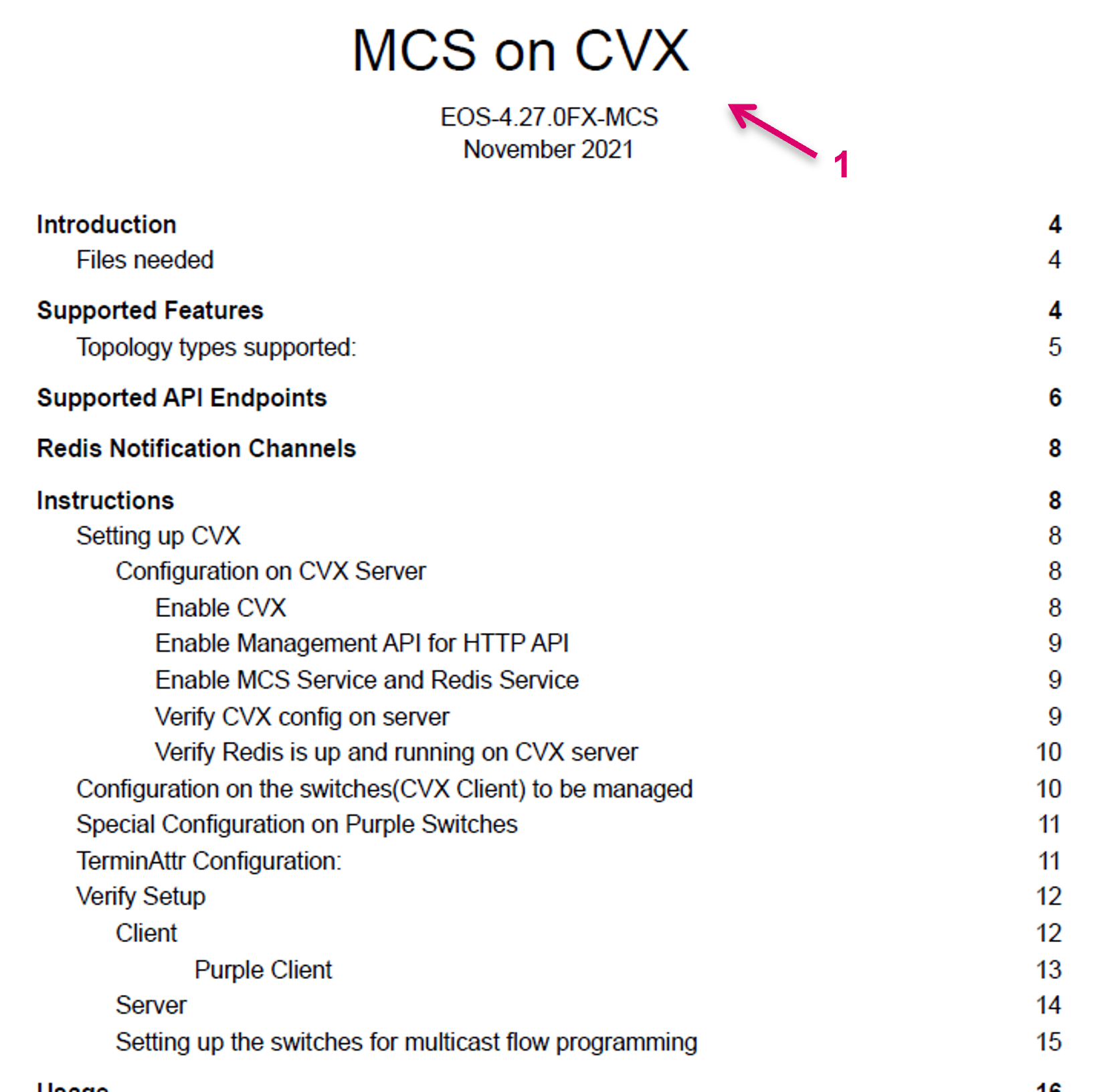
This documentation describes the setup with focus on the VSM related configuration part and is based on . The general network setup and configuration requires a good understanding of IT and networking basics. Also individual, and System specific requirements may have to be considered. Therefore, please refer to your local network architect and follow the Arista documentation (1) for the initial network design and setup. Please note that a Layer3 Network design is presumed and the use of Vlans is not supported at this time. The final network design must be aligned together with Lawo project engineering.
Setup CVX interface in vsmGadgetServer
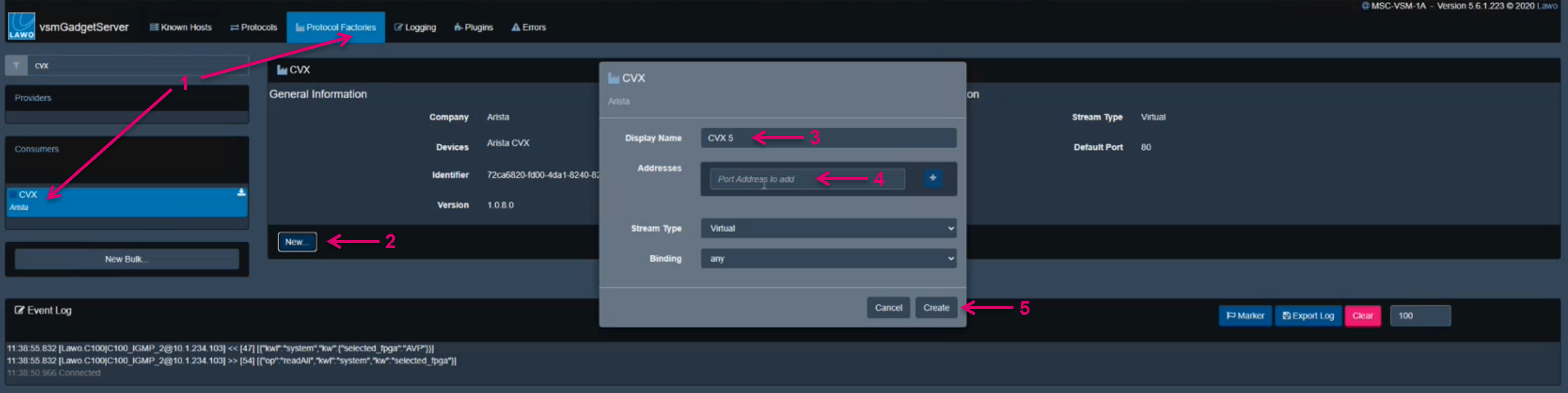
- In vsmGadgetServer setup a Consumer Port by selecting “Arista CVX” from Protocol Factories (1).
- Confirm with New (2).
- Assign a Display Name (3) and the IP Address of the respective CVX Server (4).
- Confirm with Create (5).
Provider Port and System Mapping
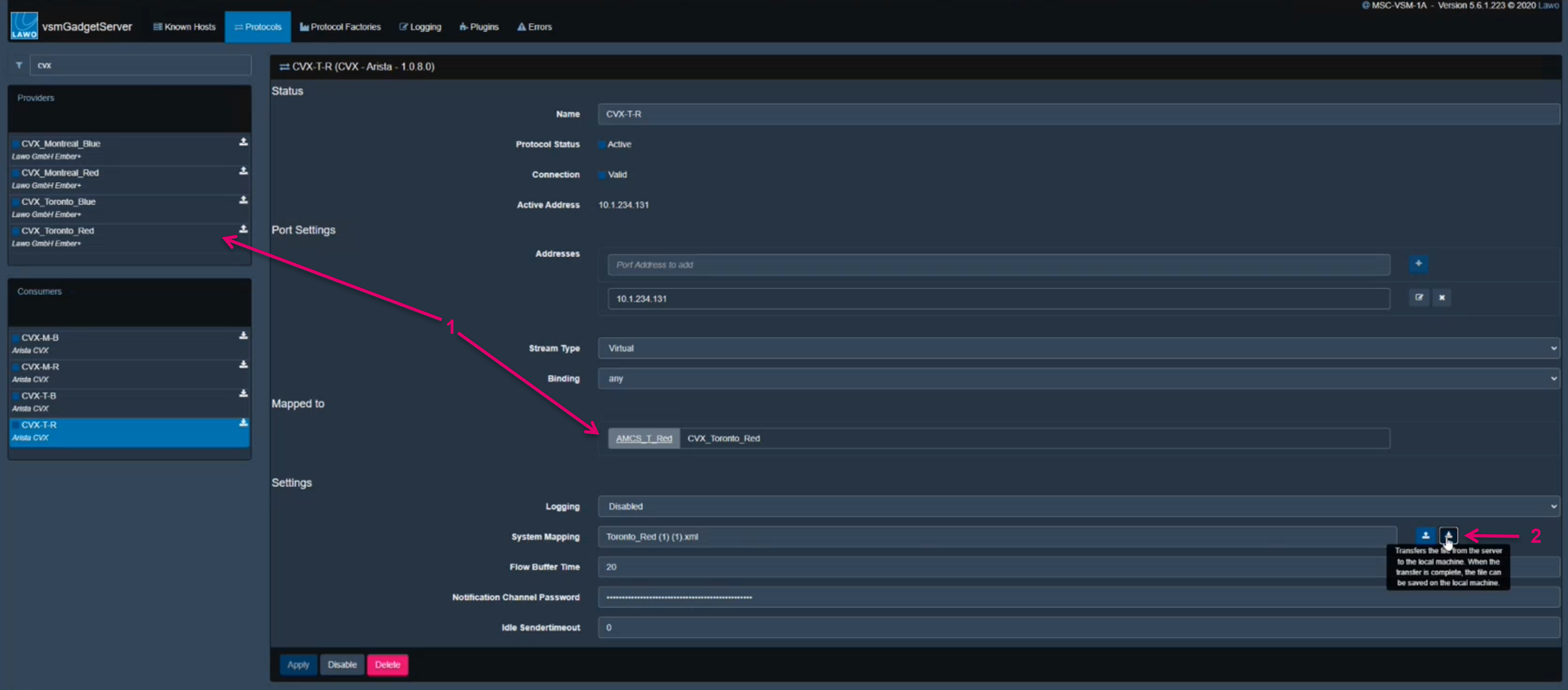
Create a Provider Port for vsmStudio and map the respective CVX Consumer Port (1).
Part of the consumer settings is a mapping file, that is created automatically after successful connection to CVX and describes the current network topology. It can be downloaded to the local machine (2) for possible modifications.
Manual action in the mapping file (1) gets important if switches need to be replaced or the CVX connection possibly must be moved to another vsmGadgetServer at a later stage. If switch hardware is replaced a manual modification of the mapping file is required, or alternatively a re-configuration of the related Network resources in vsmStudio.
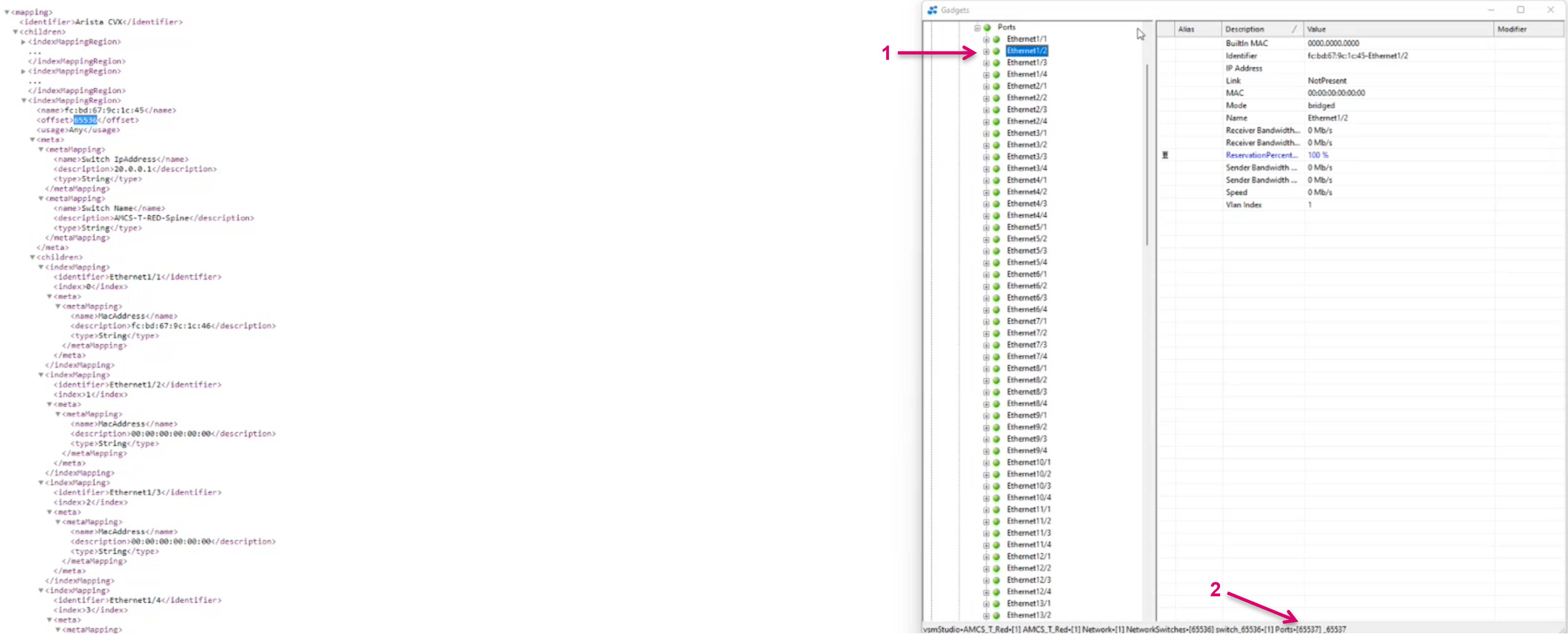
After downloading the mapping file, it can be opened and edited in any text editor, e.g. Notepad. In the mapping file, all Switches reported through CVX are listed. A unique identifier offset ID (1) per Switch (2) is automatically generated by vsmGadgetServer once a switch was connected the first time. It is also displayed in the Gadget tree in vsmStudio (3).

This offset ID defines the starting point for all underlying Switch port IDs (1) that effectively are the resource references (2) for vsmStudio on any following configuration step.
The connection of any new Switch hardware will get another/ new offset ID assigned, so a manual modification of the mapping file will be necessary. Modification means, changing the offset ID number for the new hardware to the previously used offset ID, which was introduced with the old and now replaced hardware. If the switch replacement includes even a different type of switch hardware, additional modification of the mapping file may be needed. This depends on the respective hardware since some values or descriptions may differ in between different switch types. For instance, the Port identifier may be named different which also will break the path reference in vsmStudio. Depending on the size of the system and configuration either a modification of the mapping file or the re-configuration in vsmStudio may be applicable.
If the CVX connection is moved to another vsmGadgetServer in a functioning system, the mapping file should be moved as well to keep the same structure and resource mapping for vsmStudio.
Flow Buffer Time
VSM can send bulk commands to CVX instead of only single commands. This improves the overall performance of the System. The Flow Buffer Time (1) defines the time that GS collects single messages before sending them out in one post message. The Flow Buffer Time can be set as millisecond value. The default is 0 and the chosen value depends on the individual system requirements. While a higher Flow Buffer Time introduces obviously a minimum delay even for single commands, the improved performance may still be a benefit if, for instance, recalling Storage Groups, etc.

Notification Channel Password
The Notification Channel provides CVX Notification messages to the VSM system and requires a password. The Notification Channel password (1) is set by default to “arista” and does not require any manual modification, if the Password was not changed on Arista side for any reason.

Idle Sendertimeout
Do not modify the Idle Sendertimeout (1) parameter value. This can be considered a legacy parameter that, if configured other than the default “0” will affect the system performance. This parameter was originally introduced to “clean up” unused Senders. This value in minutes defines the time after unused senders will be deleted from the CVX database. Since the process of creating senders in CVX is quite slow and takes most of the process time on initial individual Sender request, this would slow down the system performance significantly. State today, there is no need anymore, to delete unused Senders.
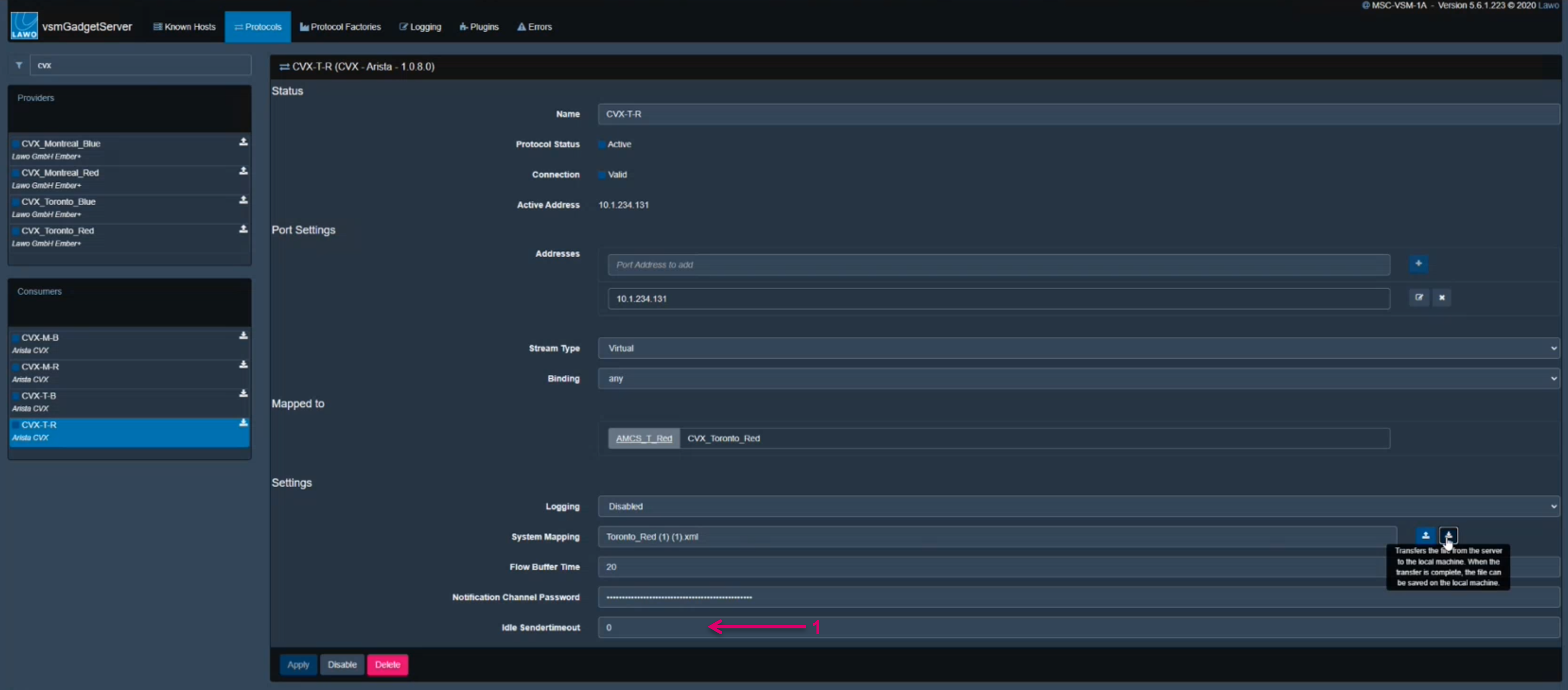
To finalize the port setup, confirm the process with Apply (1).

Setup in vsmStudio
- First set up a control port to the respective vsmGadgetServer Provider(s) for CVX under Manage Communication Ports. If not done already, create Video/Anc and Audio Network layers and Signalpaths in vsmStudio as usual.
For the time being, a specific sequence to open windows is required, therefore please first close all sub-windows in vsmStudio, then follow the sequence as described below.
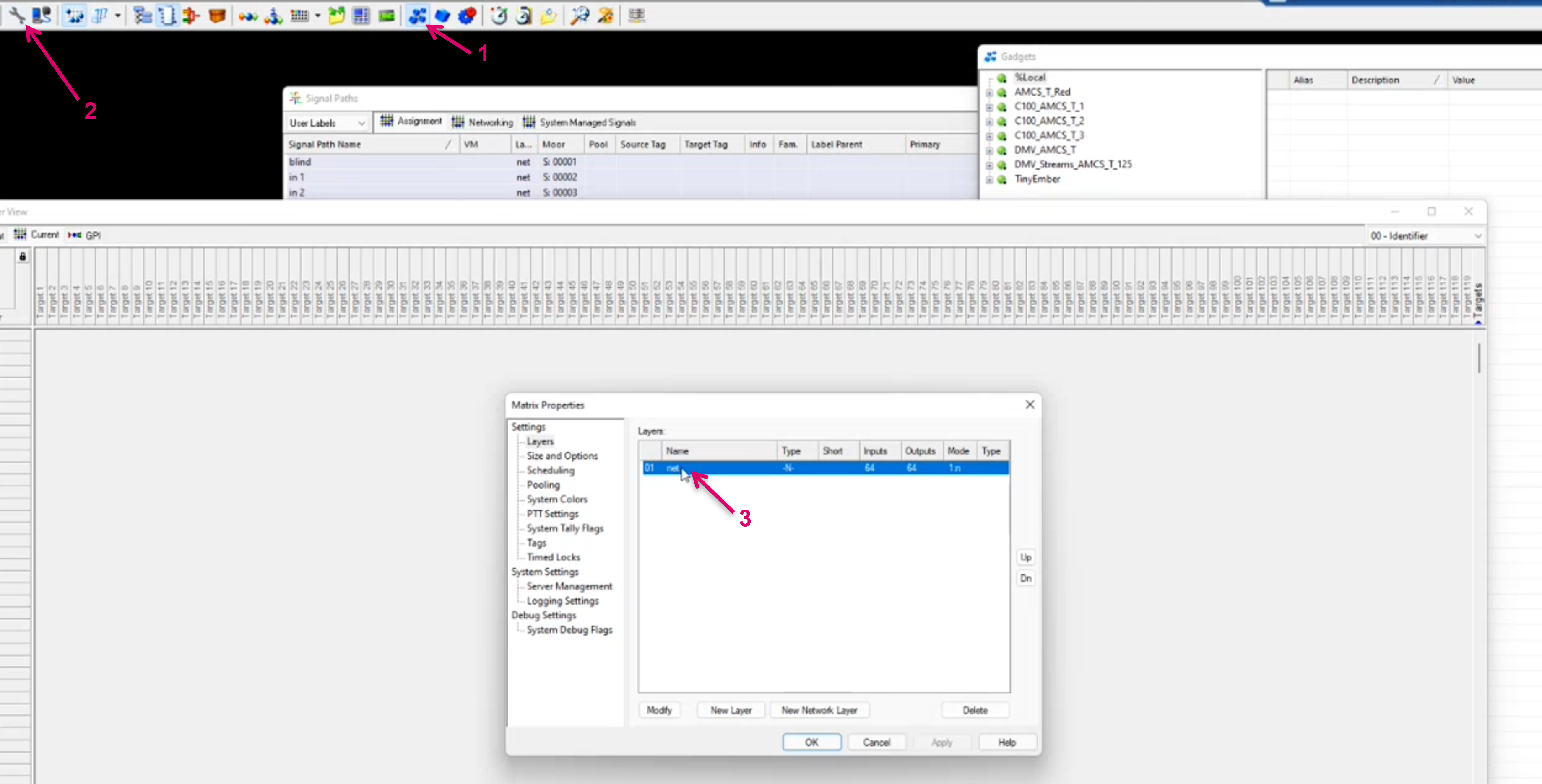
- Open the GadgetTree (1), then get any other window in focus, for instance the Matrix view, first then open Matrix Properties (2).
- Then open the Properties of the respective Network Layer by double-click (3).
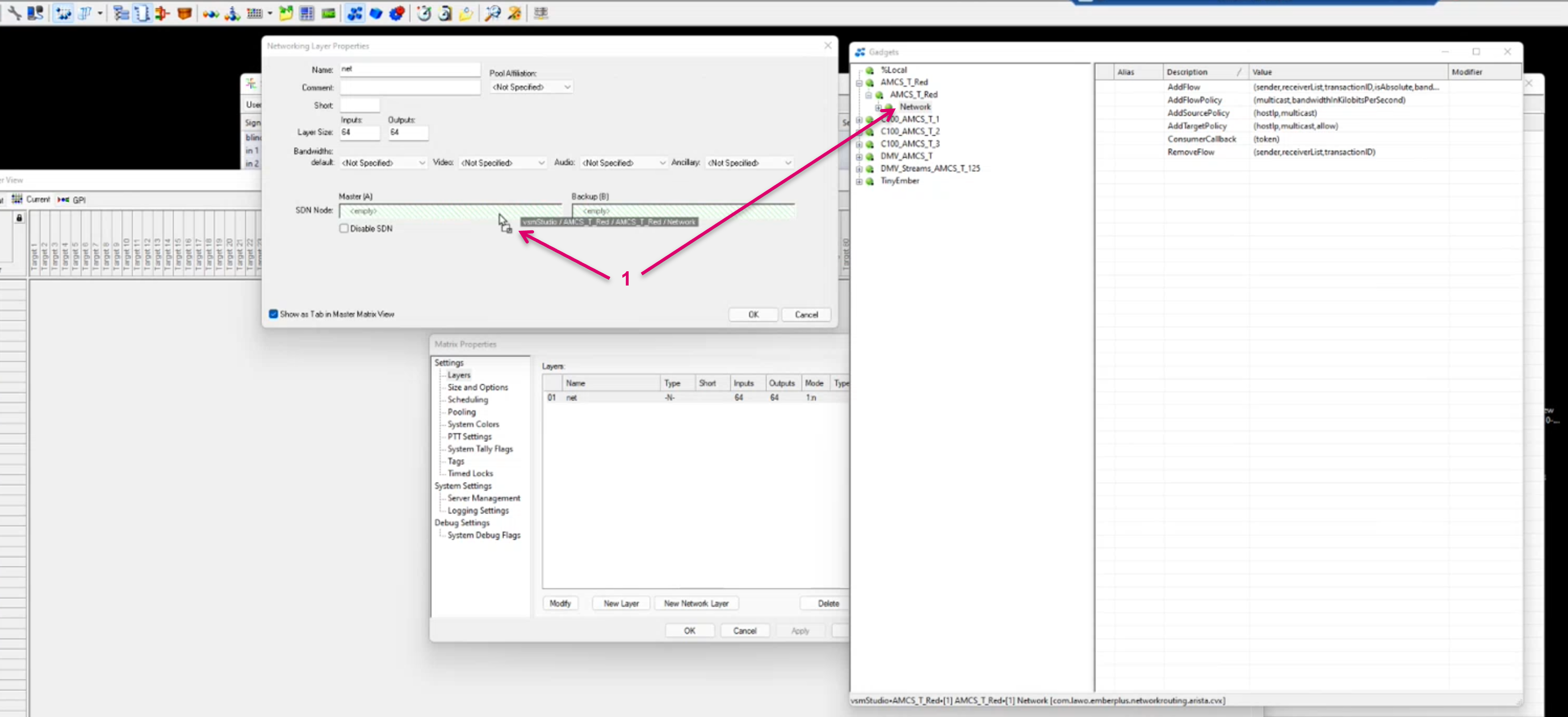
- In the GadgetTree navigate to and expand the CVX node, then drag & drop the Network node into the respective SDN Node drop zone for Master (A) in the Network Layer Properties (1).
- Do the same for a second CXV controller Node and respective Backup (B) if applicable.
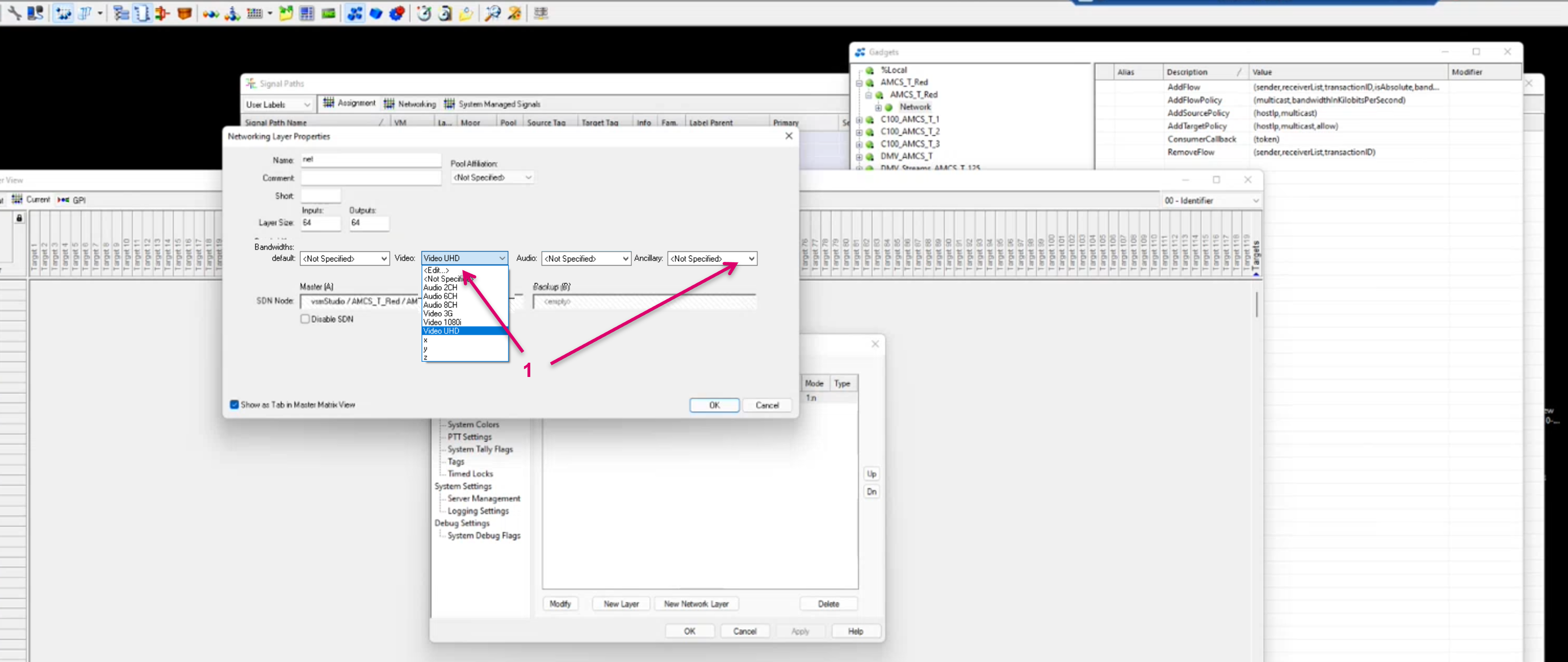
- You must specify the Bandwidth default for each flow essence that is handled via the respective layer. This is the case for Video and Ancillary/Metadata since these essences must always be assigned to one and the same layer. Assigning the appropriate Bandwidth default for the respective essence assures to reserve realistic bandwidth via CVX.
- If already configured beforehand, select the respective Bandwidth from the drop-down menu or select <Edit…> to create a new Bandwidth entry or modify an existing (1).
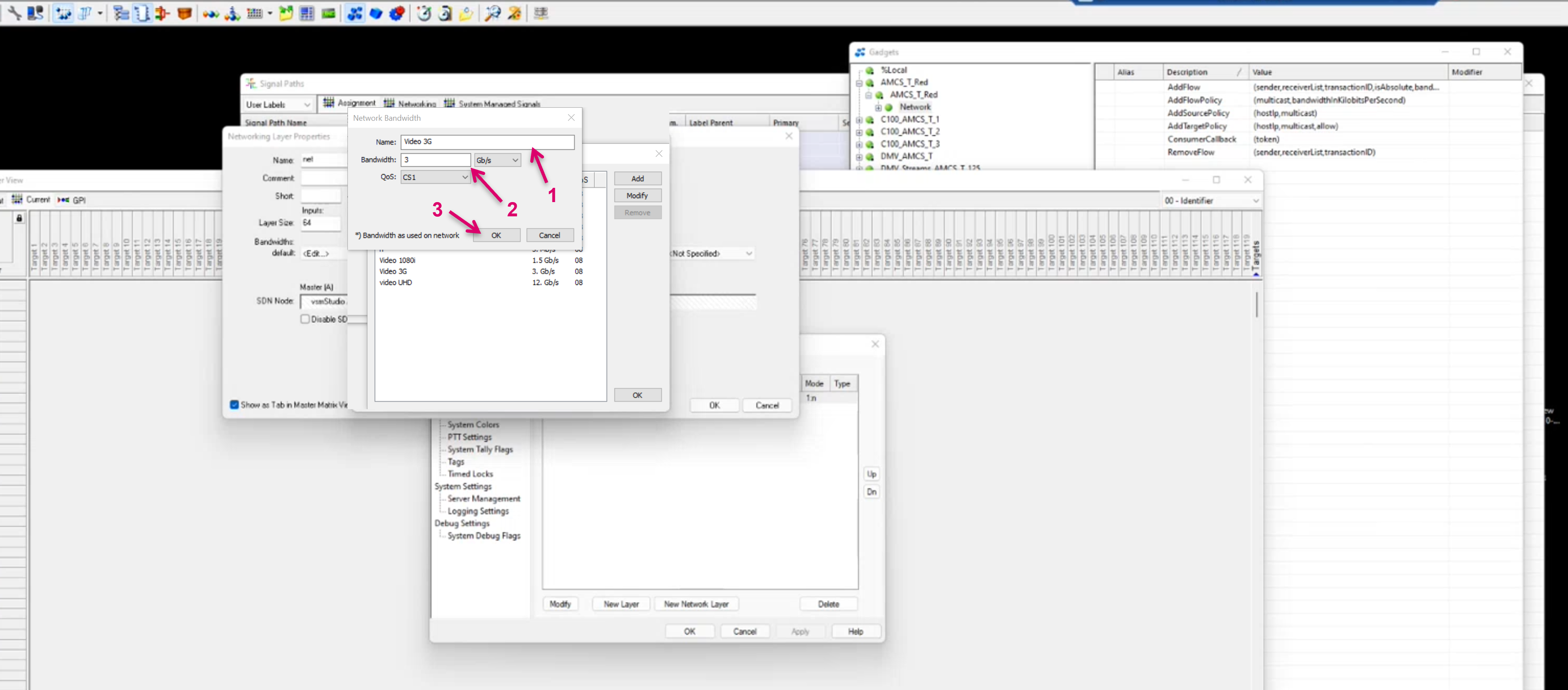
- In <Edit…> mode, you can create or modify a default bandwidth entry in Name (1), Bandwidth (2), QoS.
- Confirm with OK (3).
In addition to the default Bandwidth setting on the network layer, there is also the option to set the Network Bandwidth per Signalpath (1). Note that the setting on Signalpath level has a higher priority and will overrule the layer default.
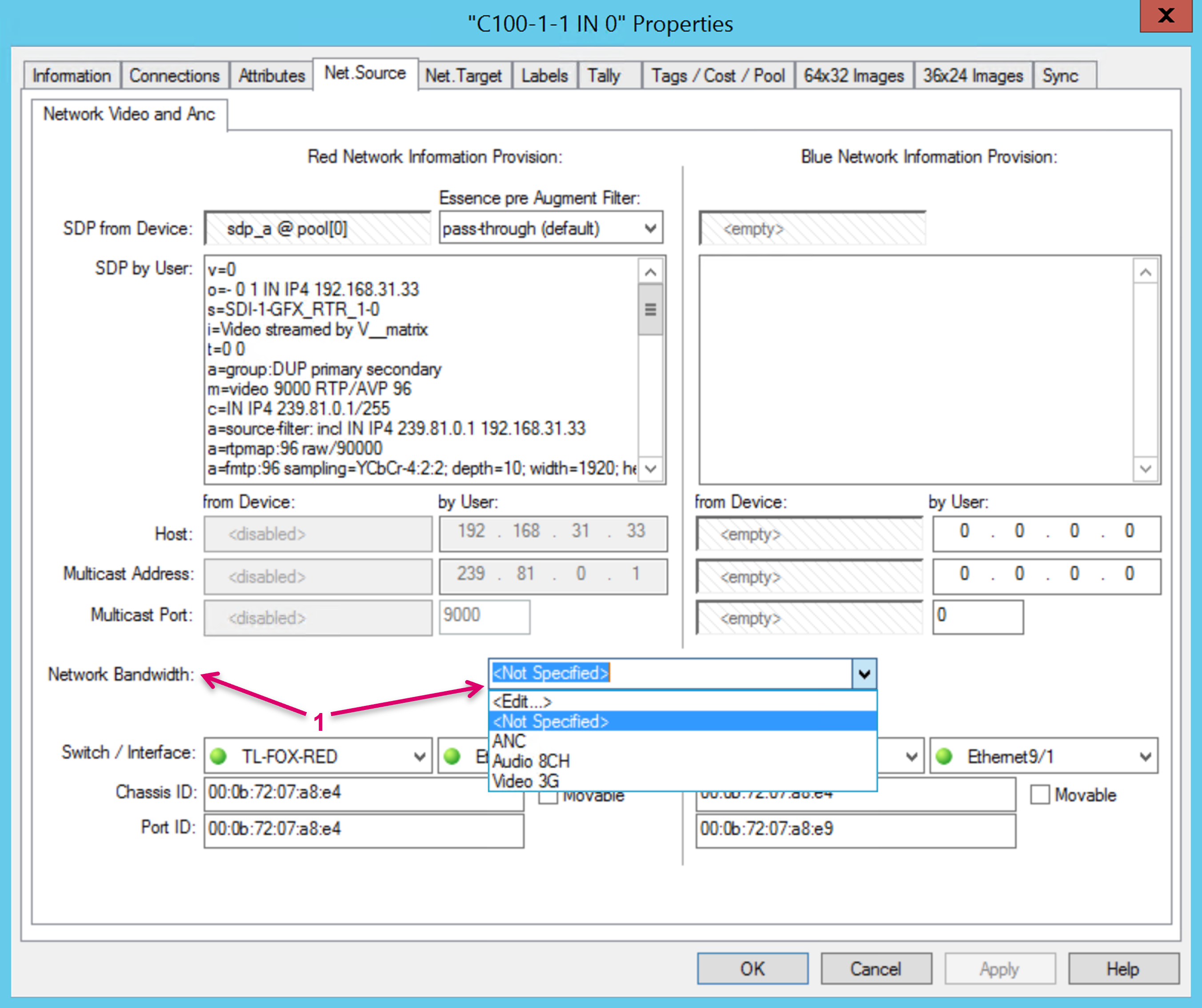
An already created Network Bandwidth can only be deleted/ removed if not used anywhere in the system.
Disable SDN Option
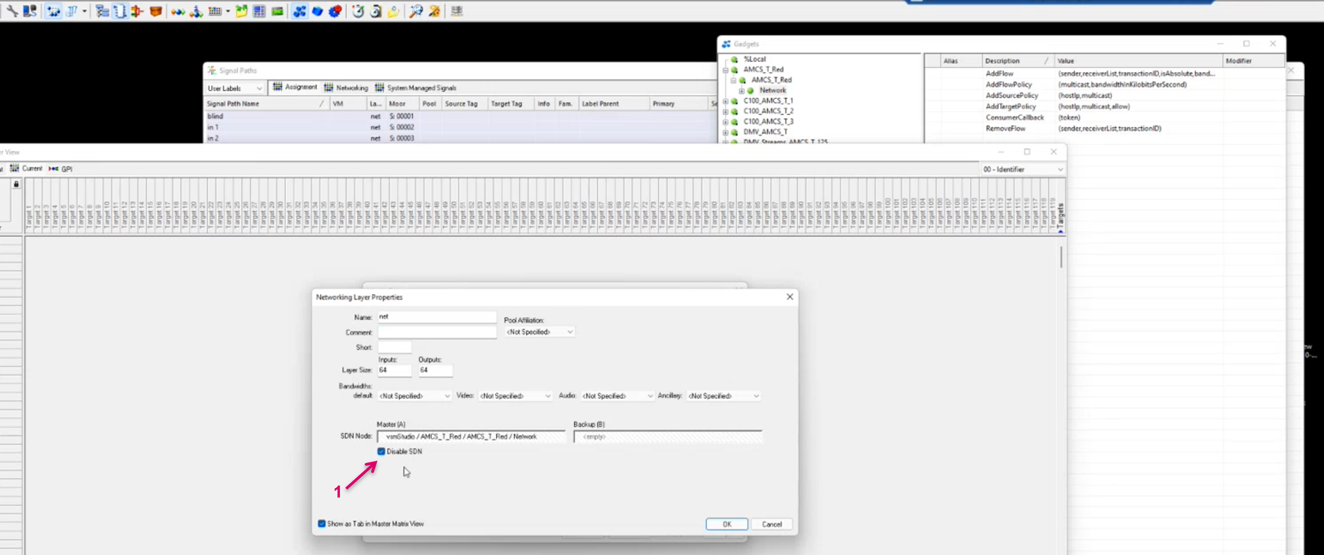
The Disable SDN option (1) allows to patch flows in a conventional way, effectively based on IGMP. If this option is enabled, VSM will ignore SDN related layer and signal path configuration details in respect of CVX command feedback. Outgoing messages will still be sent. To disable also any outbound SDN related information and avoid any unexpected behavior on the network side, it is strongly recommended to also disable the CVX related communication ports in vsmStudio. Anyway, also a change in configuration on the Arista network side will be required to switch between CVX and IGMP/ non-controlled routing. The Disable SDN option may be useful in preparation-, configuration-, or test scenarios, where the controlled SDN network may need to be disabled and at the same time, the SDN based VSM configuration is in use.
As a result, switching between enabled and disabled SDN mode may lead to wrong/ unsynchronous system status between CVX and vsmStudio. Therefore, it is highly recommended to follow a specific action sequence if making use of this option:
- Blind all receivers in vsmStudio
- Make use of the clearRoutes command with CVX via Postman (1). This effectively clears all Senders, Receivers and Routes.
![]()
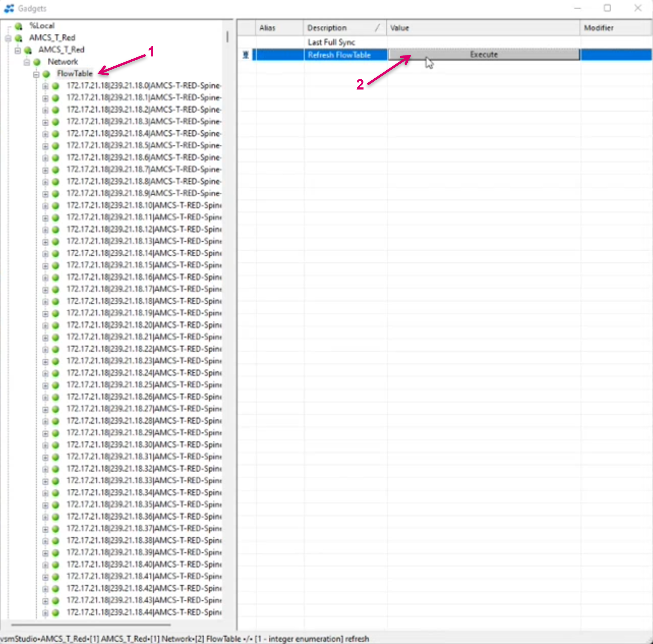
Since CVX does not actively inform VSM about the executed clearRoutes command, it is mandatory to subsequently and manually Refresh FlowTable via the respective CVX/Network Sub node in the vsmStudio GadgetTree. Select the FlowTable Node (1) and Execute Refresh FlowTable (2). This action triggers vsmGadgetServer to poll the current status from CVX.
Since all existing Senders in CVX are deleted with the clearRoutes command, the next routes, with enabled SDN mode, will again take more time to execute, because Senders must be created again in CVX. The initial creation of senders is, as mentioned in a previous chapter, the most time-consuming CVX processing step when a flow route is requested.
- Create Network Source and Target Signal paths as usual.
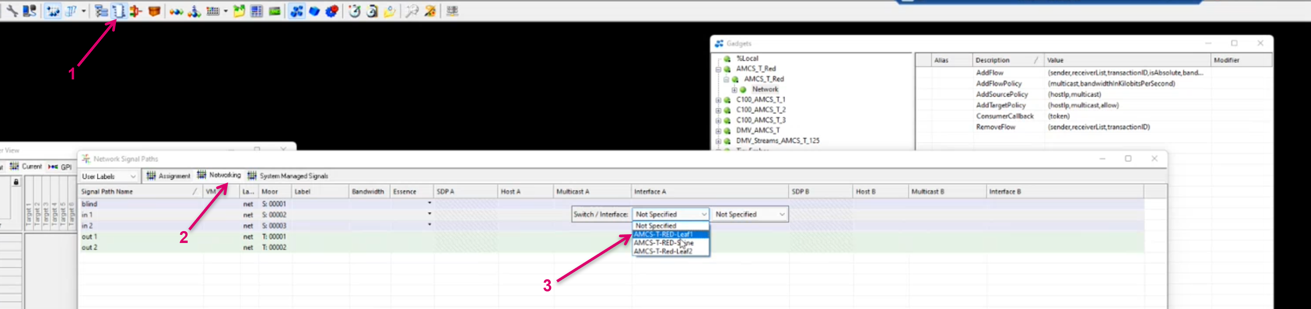
- Open the Signal Paths List (1) and navigate to the Networking tab (2).
- For each Signal click into the Interface A (and B) column and select the Switch to which the selected Signal is connected (3) from the pull-down menu.
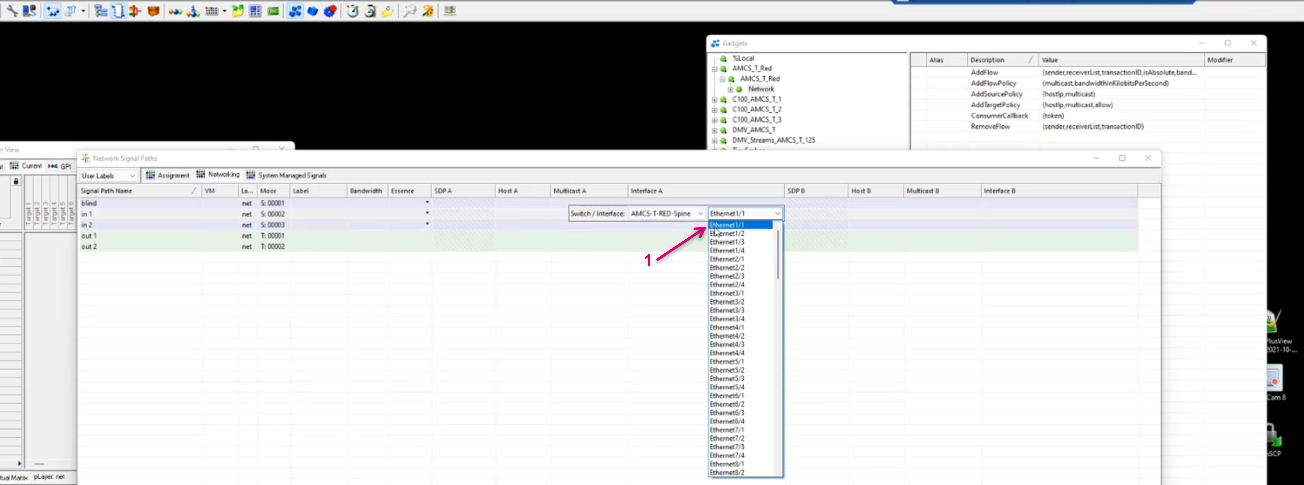
Select the respective Ethernet Interface/ Port for the selected Signal (1).
- Open the GadgetTree Window (1)
- Navigate to the Signal related SDP parameter and drag & drop the respective parameter to SDP A (and B) columns (2).

After any network related changes in the config, save, close and re-load the configuration.
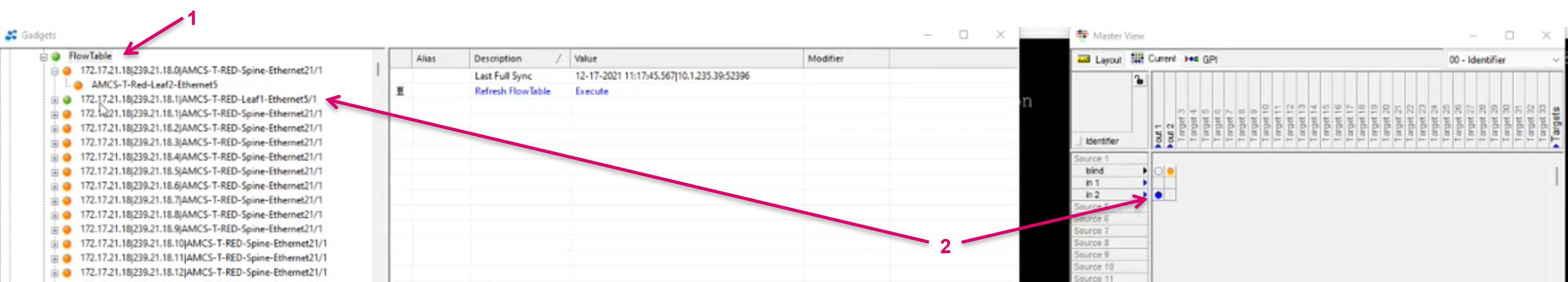
The current Route status as reported by CVX can be found and checked in the GadgetTree under the FlowTable node (1)(2).
Network Flows View
The Network Flows view provides an overview about current flows on the network, exclusively in combination with an Arista CVX install. While it would be desired to read the absolute network status from such view, due to the complexity and variety of IP broadcast systems in the field, this view is mainly a helper tool to monitor the current operational status, based on the available information provided by the network controller. There will be cases, especially in troubleshooting scenarios, where it will be required to also check status on CVX and network switch level directly.
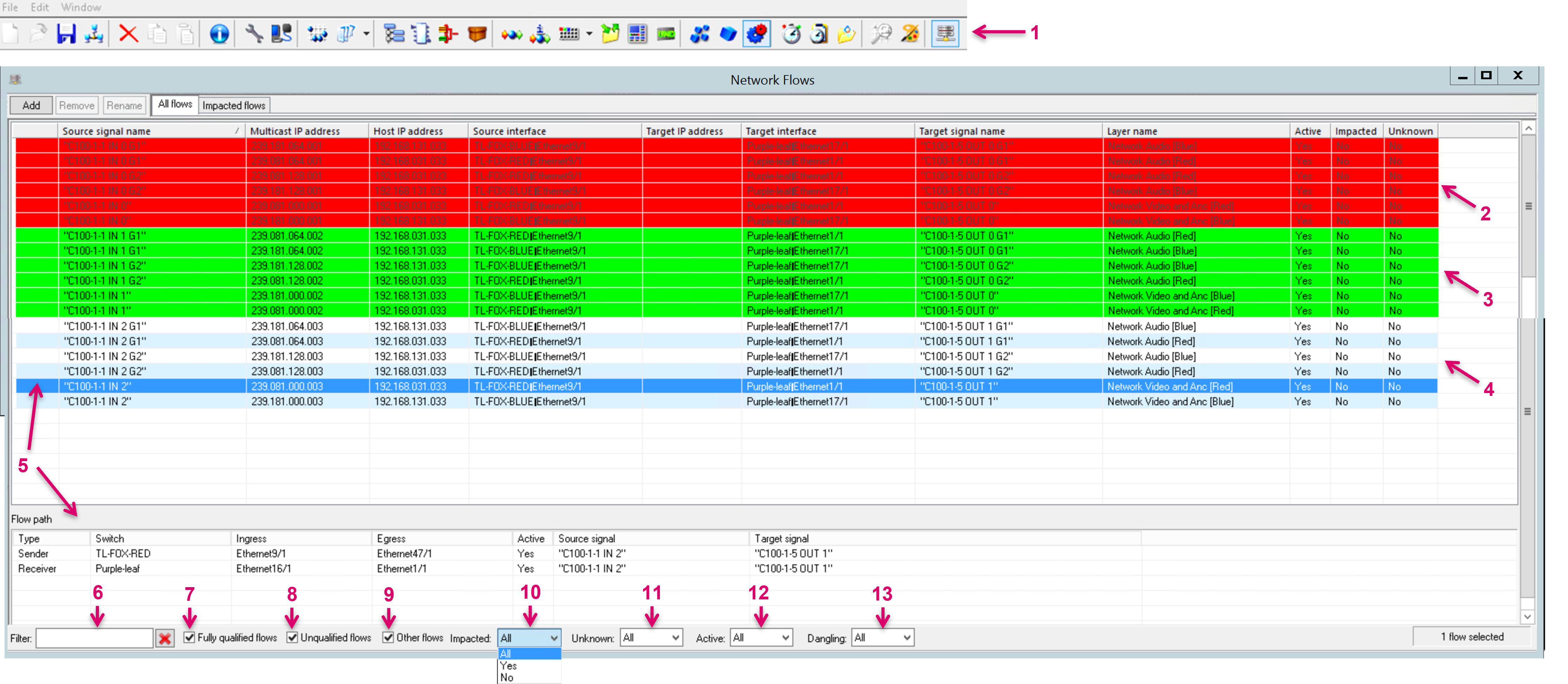
- Open the Network Flows view from the vsmStudio toolbar (1).
- A post and delete flow command is signaled with a colored background. If for instance changing the source of a target (in the below example followed by ANC and Audio Signals as per Pseudo Device rule), you can see the previous Source to Target flows showing shortly with red background (2) before disappearing from the list and the new Source to Target flow highlighted green (3), before remaining in the list with the default background (4).
- Selecting any row entry, brings up more details on the flow in the Flow path section (5).
- The window provides a text entry field to Filter list entries (6).
- You can directly filter by checkboxes (7-9) and pull-down options (10-13).
Legend:
- Fully qualified flows (7): Flows where Source and Target signal names are known, means a Signalpath is existing in the vsmStudio configuration for both, Sender, and Receiver.
- Unqualified flows (8): Flows where Source and Target interfaces are known.
- Other flows (9): Flows with Source and Target Multicast-address but not known by signal name or interface.
- Impacted (10): Status reported by CVX for existing flows with a broken route within the network topology.
- Unknown (11): Interpreted Status based on reported CVX messages in regards of unavailable flows, corrupted sender, leftovers, etc.
- Active (12): Status reported by CVX for active flows. A “No” here could indicate the Flow exists but the current Sender is disabled.
- Dangling (13): Flows for which the Network Flows View could find a source and target signal, but the source signal is NOT the physical or expected physical or network source of the target. Therefore it's assumed that the deduction is based on outdated information, and the flow is marked as dangling.
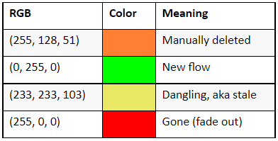
Color Code:
Support of “moving” Devices
Some workflows require devices to be physically moved, even during production and across the facility. In this application, may also be called “Wallboxing”, a device may be disconnected from on physical network interface and plugged back into another network port and the desired workflow is that the device will be available again right after and, in case of a target, even receive its previous source signal. From a controller perspective those devices must be considered as movable devices. For the respective Signalpaths in vsmStudio, this would mean that also the configured network interface would change. For these movable devices, VSM provides a feature that, based on a Movable (1) flag in the respective Signalpath properties, allows to move to a different interface without any re-configuration. Even current flows will be re-routed accordingly after moving. In vsmStudio, the device must be configured on any Network interface once, and with the Moveable flag set. It will henceforth be identified by its LLDP information (2).
Preconditions are:
- The device must support the Layer3 network configuration
- The Control Unicast IP must remain the same
- The device supports LLDP
- The combination of Chassis and Port ID must be unique within the network


By design, a remove flow command is sent per Interface that gets unplugged. If both (red and blue) Interfaces are unplugged and even only one of them is plugged in again, an add flow is sent for red and blue regardless of a common interface state.
Devices supporting internal signal loopback
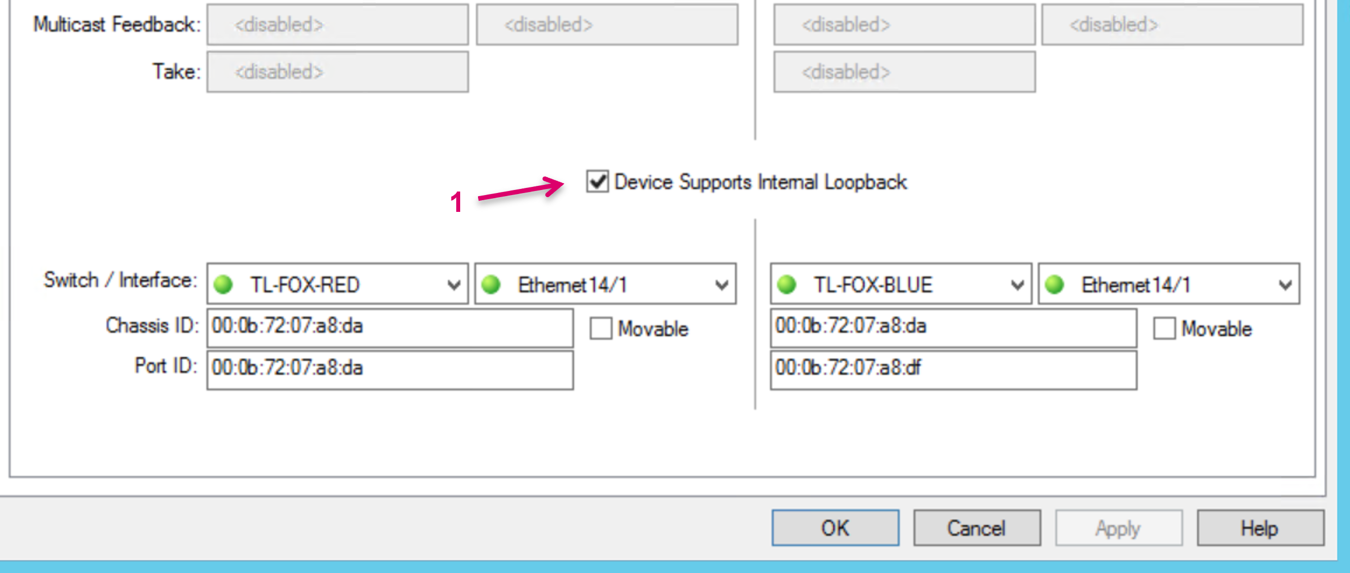
Some workflows require that on the same device, a local target signal is re-entered as a local source. While this could be achieved with a local internal routing crossbar, if so available, it becomes more difficult in IP only systems or where no local crossbar is available. In this case the stream sender would need to be received on a local stream receiver via the same network interface, which is not possible due to basic networking rules. vsmStudio would not even allow to set such a crosspoint due to the conflicting network interface configuration on the Signalpaths. For the described application, some devices may support an internal loopback mechanism that internally distributes signals where needed, based on the patched SDP information. Lawo’s Powercore is an example for a device that supports internal loopbacks. In vsmStudio a special flag has to be set to identify respective Signalpath targets. Please check the Device Supports Internal Loopback box (1) on the Net.Target Tab in the Signalpath settings.
For such flagged network targets, vsmStudio will allow that crosspoints can be set accordingly and display these crosspoint as confirmed after the SDPs are also confirmed by the device.
Devices supporting grouped SDP for Video and Metadata
In an SDN/ CVX environment, single essence SDP data is mandatory. Means, if the Source contains more than one SDP data entry for any essence, these will not be considered with the route.
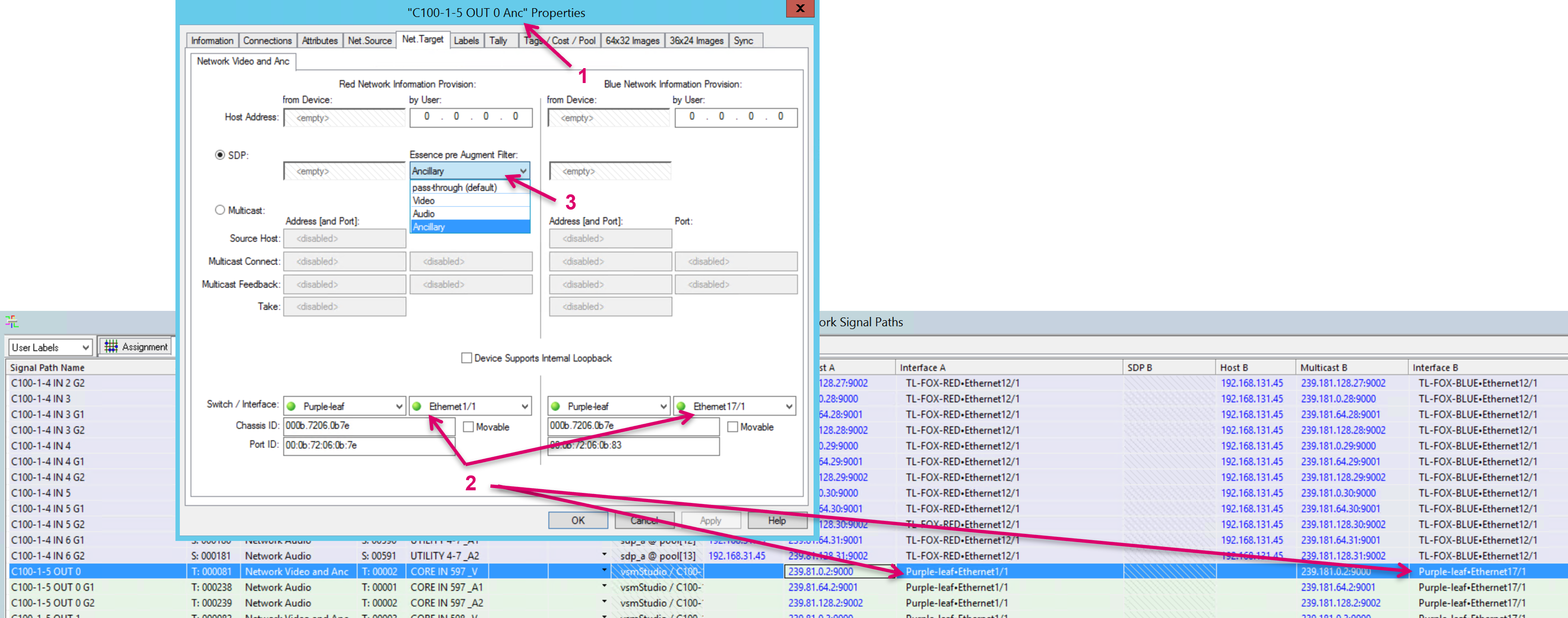
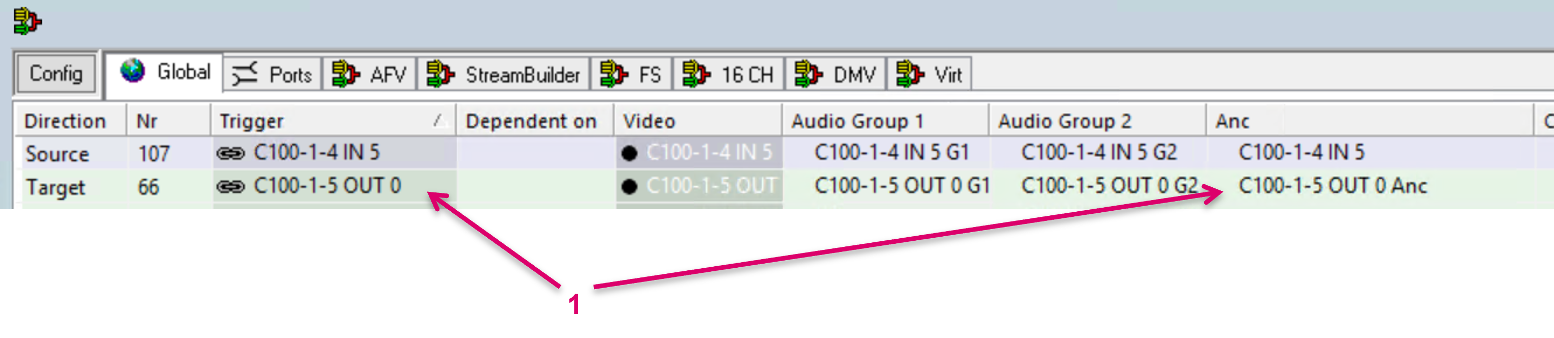
In order to support target-devices that only support grouped SDP for Video and Metadata, for instance Lawo C100, a specific Signalpath configuration approach is required. While there would basically be only one (Video) target Signalpath configured, for setting up flows via CVX it still requires a separate target Signalpath for the Metadata essence.
- An additional “dummy” Signalpath for Metadata/Anc must be created (1) on the Video/Anc-Network layer per such Video target.
- With the same switch interface assigned like the Video (2).
- With the SDP Essence filter being set to Ancillary (3).
- No SDP parameter must be assigned to this Signalpath.
- The Metadata/Anc dummy then must be combined with the Video Signalpath in a Pseudo device rule (1).
In a CVX controlled system it is currently not possible to use network Tielines together with receivers that expect grouped SDP, containing Video and Metadata information.
Distributed Multi Viewer Assist - Module
Introduction
Lawo’s DMV, with its internal signal distribution management and resource sharing requires a special handling in combination with a SDN controlled network routing infrastructure. Additional information that must be shared with the broadcast controller to ensure that network flows will be routed to the correct cluster node. For this, vsmStudio provides a special module that effectively monitors all necessary information. The utilization of the module is mandatory to ensure proper routing into the DMV in a CVX controlled environment.
Module Setup
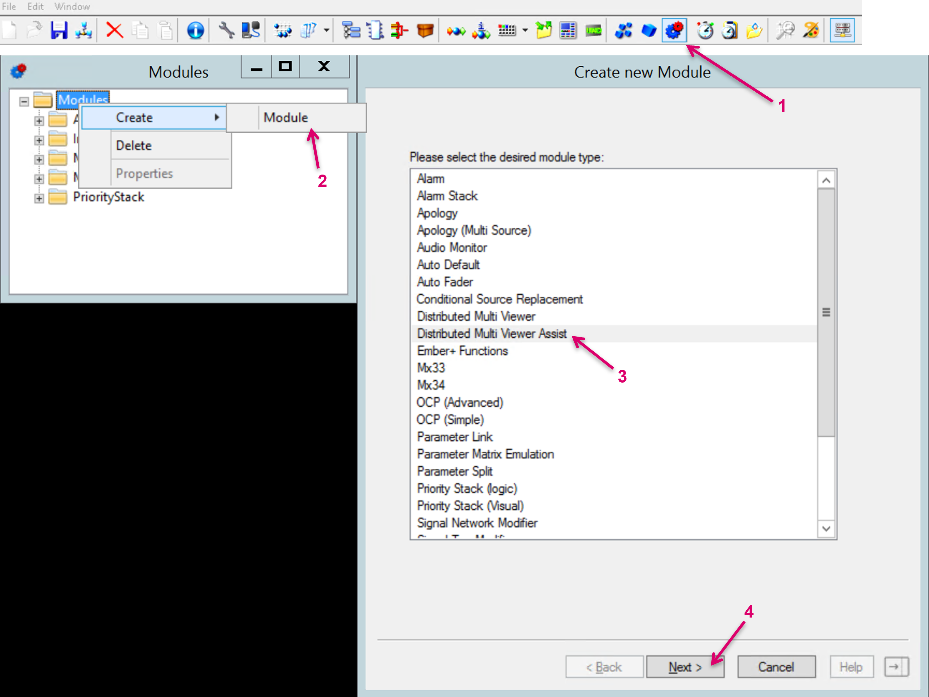
- Open the Modules window from the vsmStudio toolbar (1).
- Open Modules/Create/Module (2). Select Distributed Multi Viewer Assist (3).
- Proceed with Next (4).
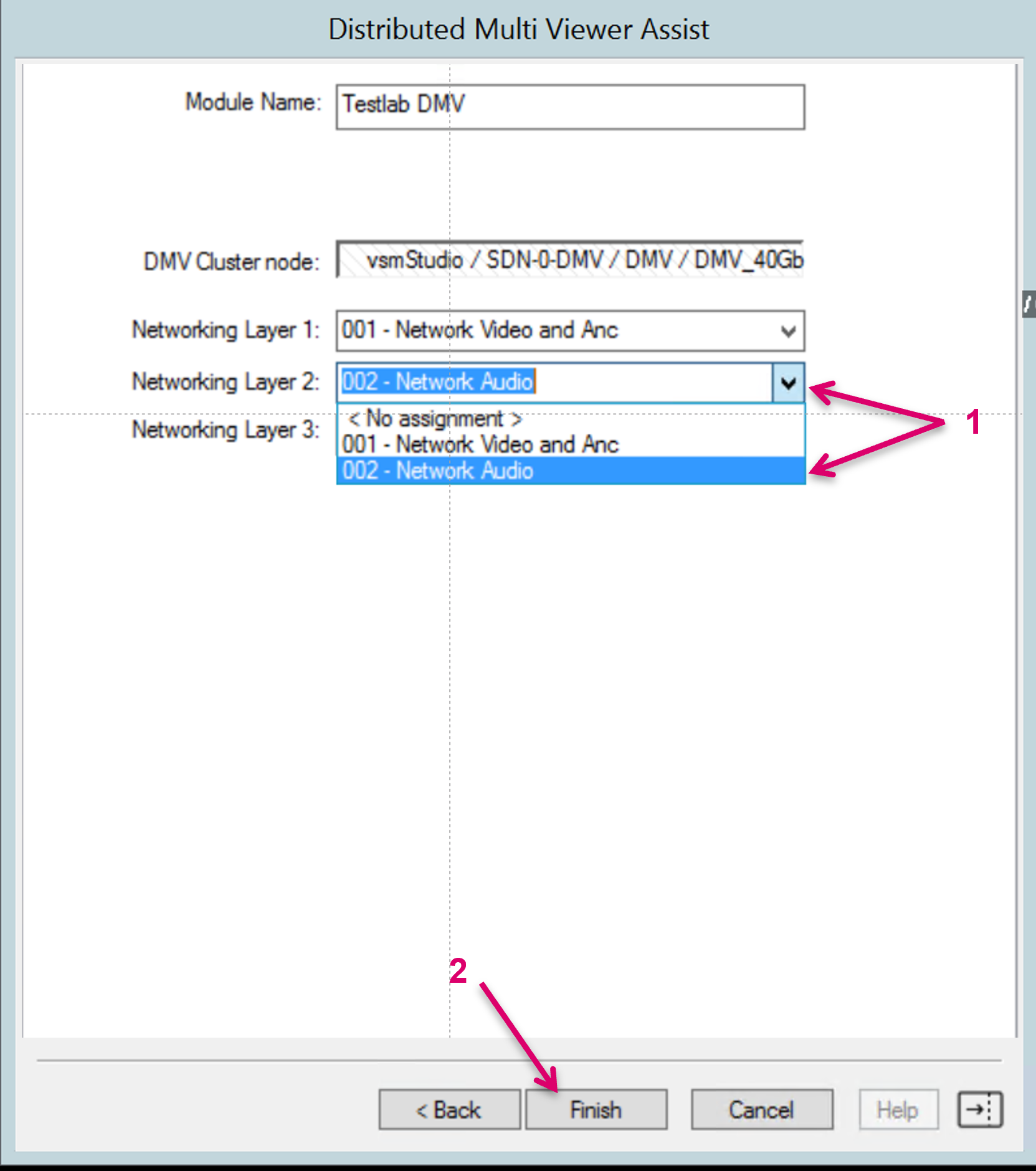
- Assign a Module Name (1).
- Open the Gadgets window and drag & drop the DMV Cluster node from the DMV Gadget tree into the respective drop-zone of the module (2).
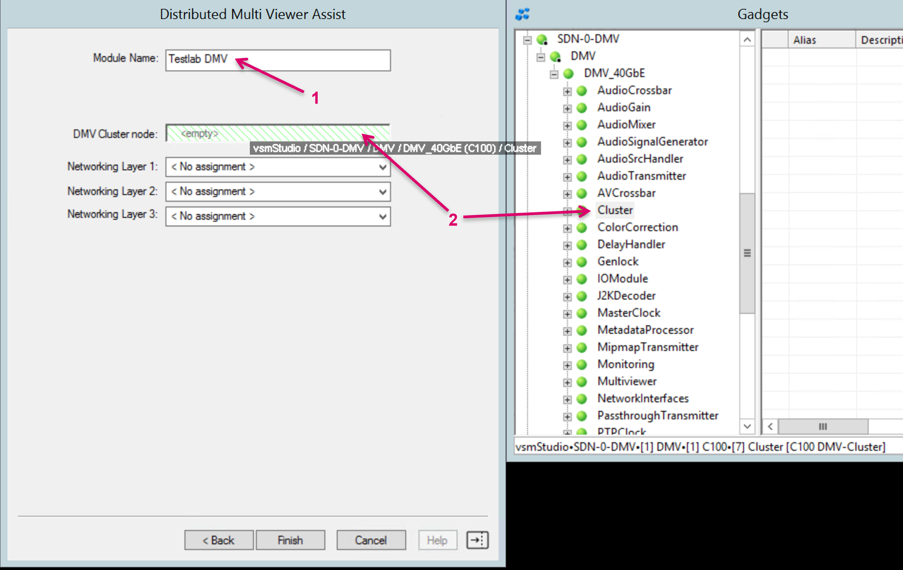
- Select and assign the available network layers of the running configuration to the Networking Layer fields (1).
- Finalize the module setup with Finish (2).