vsmStudio - Signal Paths

Introduction
Signal Paths are core elements in any VSM system configuration. If vsmStudio is to control signal sources and targets, no matter if these are representations of physical resources or virtual, then these resources must first be configured in form of Signal Paths. These Signal Paths then allow for example, to connect inputs and outputs or just handle logical connections by connecting Signal Path source and target. Signal Paths are used and operated via Matrix views, on Panel buttons or secondary logic, e.g., triggered by GPI.
Overview of the Signal Paths views
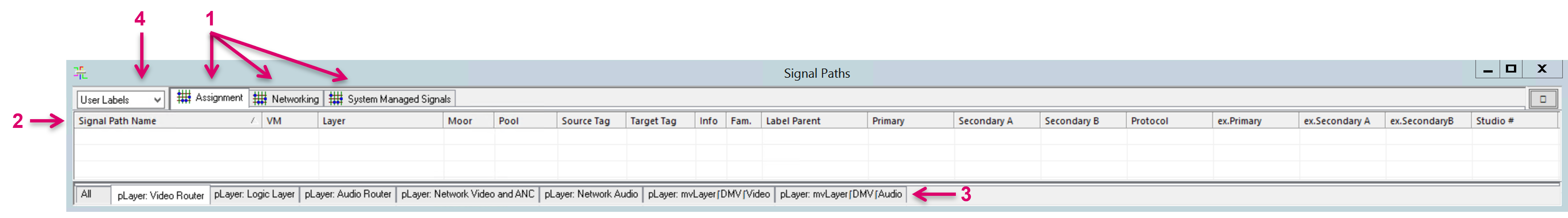
The Signal Paths view is the starting point to create new or modify existing Signal Paths. Tabs on the top of the Signal Path window give access to various Signal Path list views (1), which contain all physical, virtual and system managed Signal Paths that were created within the current active configuration. Various columns provide an overview of their configured attributes (2). Displayed Signal Paths can be filtered per Layer, or all shown in one list, selectable via tabs on the bottom (3). The displayed Signal Path label in Label columns can be selected between their User or Default label (4).
 Assignment list
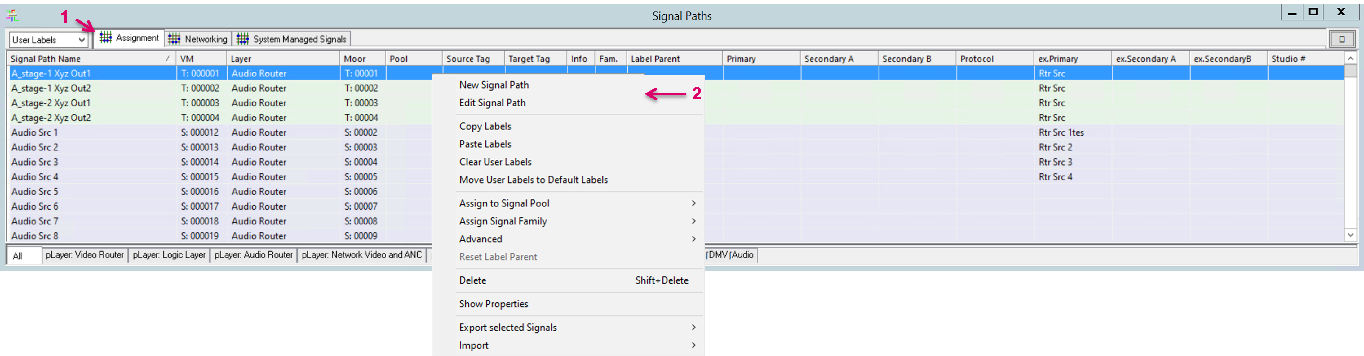
The Assignment list (1) is the main and default Signal Paths view. In here you can create, modify, and delete Signal Path entries and monitor various Signal properties. Right-mouse-click in any space of the window opens a drop-down list of available options (2). Existing Signal Paths in this list, can be modified by direct cell entries or via their respective Properties view, accessible on double-mouse-click
Available Columns:
- "Signal Path Name": The system wide unique identifier name that is set when the Signal Path is created.
- "VM": Shows the location of the Signal Path on the Primary Virtual Matrix layer.
- "Layer": Shows the physical layer that the Signal Path is assigned to.
- "Moor": Shows the configured ID/ position of the Signal on the respective physical layer. The abbreviations “S:” or “T:” as well as the background color of the respective row indicate if the Signal Path is configured as Source (purple) or Target (green).
- "Pool": Indicates if the Signal Path is assigned to a Pool. The respective Pool name is displayed (related to “Pooling”).
- "Source Tag": Future function.
- "Target Tag": Future function.
- "Info": Indicates if the Signal Path contains secondary functions or is “synced” with another Signal Path.
- "Fam.": Shows the assigned Signal Family.
- "Label Parent": Indicates if the label is derived from another Signal Path. The identifier label of the respective Signal Path is displayed.
- "Primary": Shows the primary label, set for the Signal Path. (Displayed label may be switched between Default and User label, dependent on the top selection of the window.)
- "Secondary A": Shows the Secondary A label, set for the Signal Path. (Displayed label may be switched between Default and User label, dependent on the top selection of the window.)
- Secondary B, Protocol, and following columns are further label levels per Signal Path.
All Label levels, except the Identifier (=Signal Path Name), can be renamed which may change the appearance/headlines of the respective columns. Only named label levels appear as columns in this view. Some label levels may be used for incoming external label information via protocol, depending on their ID.
It is possible to modify or add labels to Signal Paths in the Assignment view, except the Identifier (=Signal Path Name). To do so, select a Signal Path, click into the respective cell, and add or overwrite the label accordingly.
To modify the label for multiple Signal Paths, within the same column, select the respective cell of the first Signal Path, hold down shift and select the cell of the last Signal Path. Now you can enter a label in the first cell and quickly jump to the respective cell of the following Signal Path by just hitting Enter on your keyboard.
Networking list
The Networking list (1) contains all Signal Paths, assigned to a Network Layer. Specific Network related columns and attributes are displayed (2). Existing Signal Paths in this list, can be modified by direct cell entries or via their respective Properties view, accessible on double-mouse-click. Note the orange cell background which signals that the same parameter is assigned to multiple Signal Paths which may be unintended or conflicting and may need attention and or correction. Signal Paths cannot be created or deleted in this view. For this, please navigate to the Assignment tab.

Available Columns:
- "Signal Path Name": The system wide unique identifier name that is set when the Signal Path is created.
- "VM": Shows the location of the Signal Path on the Primary Virtual Matrix layer.
- "Layer": Shows the physical layer that the Signal Path is assigned to.
- "Moor": Shows the configured ID/ position of the Signal on the respective physical layer. The abbreviations “S:” or “T:” as well as the background color of the respective row indicate if the Signal Path is configured as Source (purple) or Target (green).
- "Label": Shows any assigned Primary Label.
- "Bandwidth": Shows the configured Network Bandwidth (related to SDN configuration).
- "Essence": Shows the selected Media Essence Filter.
- "SDP A": Shows the assigned, primary SDP parameter.
- "Host A": Shows the primary Host IP address.
- "Multicast A": Shows the primary Multicast IP address and Port.
- "Interface A": Shows the primary Network Switch Port (related to SDN configuration).
- "SDP B": Shows the assigned, secondary SDP parameter.
- "Host A": Shows the secondary Host IP address.
- "Multicast A": Shows the secondary Multicast IP address and Port.
- "Interface A": Shows the secondary Network Switch Port (related to SDN configuration).
System Managed Signals list
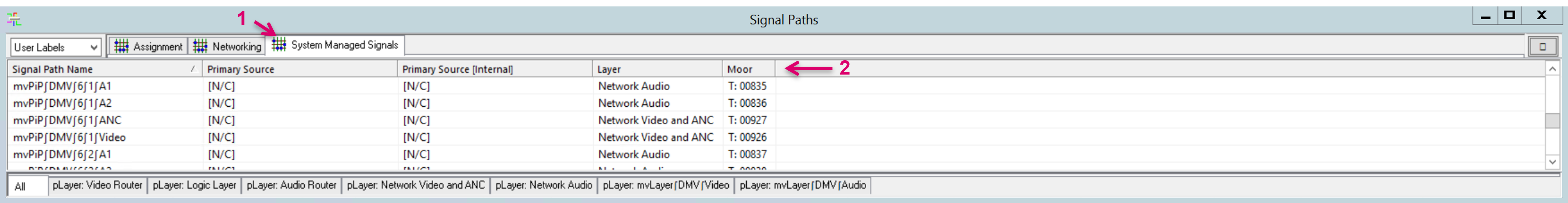
The System Managed Signals list (1) contains all Signal Paths that were automatically created by vsmStudio, for instance via the "Distributed Multi Viewer"-module. Specific columns and attributes are displayed (2). Existing Signal Paths in this list, can be modified via their respective Properties view, accessible on double-mouse-click. Signal Paths cannot be created or deleted in this view. For this, please navigate to the Assignment tab.
Available Columns:
- "Signal Path Name": The system wide unique identifier name that is set when the Signal Path is created.
- "Primary Source": Shows the current connected Source of Target.
- "Primary Source[Internal]": Shows the current connected Source of Target.
- "Layer": Shows the physical layer that the Signal Path is assigned to.
- "Moor": Shows the configured ID/ position of the Signal on the respective physical layer. The abbreviations “S:” or “T:” indicate if the Signal Path is Source (purple) or Target (green).
Signal Path Configuration
The HOME API interface allows for a simplified creation process of Signal Path resources. Please refer to therespective HOME Interface documentation.
A right-mouse-click in any space of the Assignment list opens a drop-down list of available options.
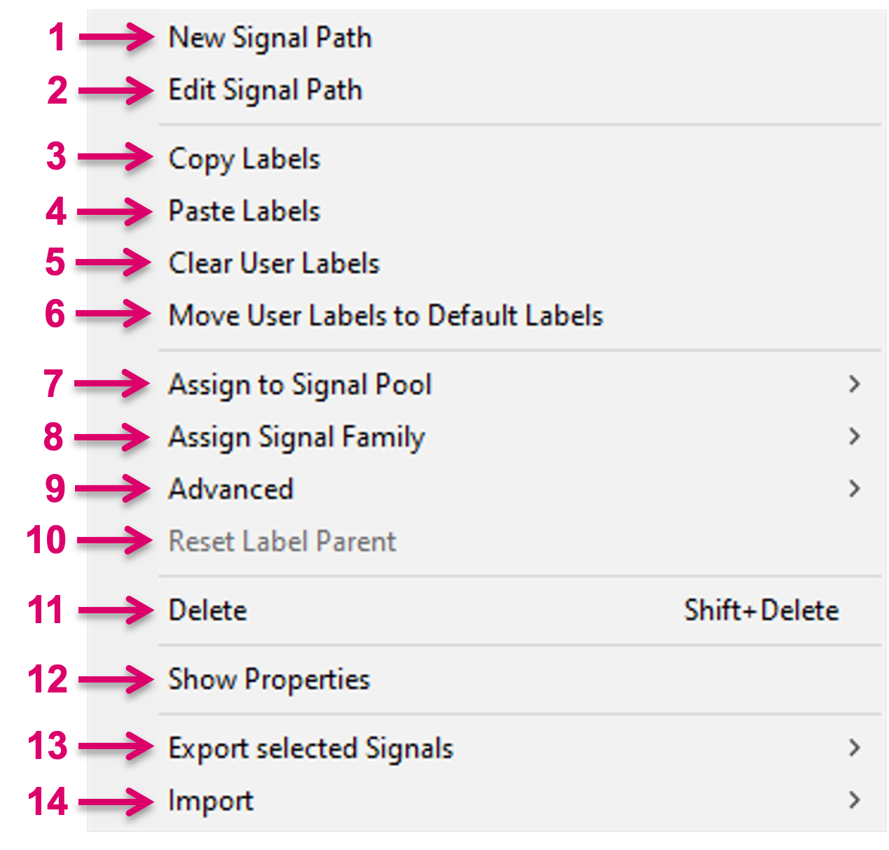
- New Signal Path: Create a new Signal Path, Virtual Signal Path or Tie-Line
- Edit Signal Path: Modify Properties of any existing Signal Path
- Copy Labels: Copy labels from selected Signal Paths to Clipboard
- Paste Labels: Paste labels from Clipboard to selected Signal Path and respective number of following Signal Paths
- Clear User Labels: Clear all User Labels of selected Signal Paths
- Move User Labels to Default Labels: Moves all User Labels of selected Signal Paths to the respective Default Column
- Assign to Signal Pool: Assign the selected Signal Path to a Signal Pool
- Assign Signal Family: Assign the selected Signal Path to a Signal Path Family
- Advanced
- Reset Label Parent
- Delete: Delete selected Signal Path
- Show Properties: Show Secondary Properties of selected Signal Path
- Export selected Signals
- Import: Import Data from Unicode Text
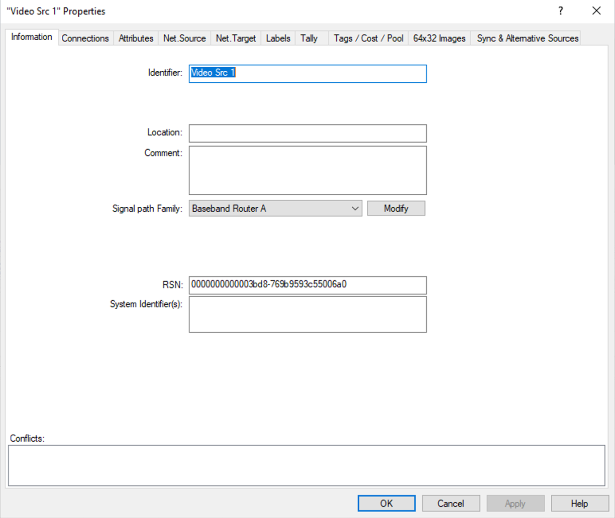
New Signal Path and Edit Signal Path
- After selecting "New Signal Path" (1) you are led through multiple windows that will guide you through the Signal Path setup process.
- Already existing Signal Paths can be modified by selecting "Edit Signal Path" (2) or via double-left-mouse-click on the respective Signal Path in any Signal Path list view or in any Matrix view.
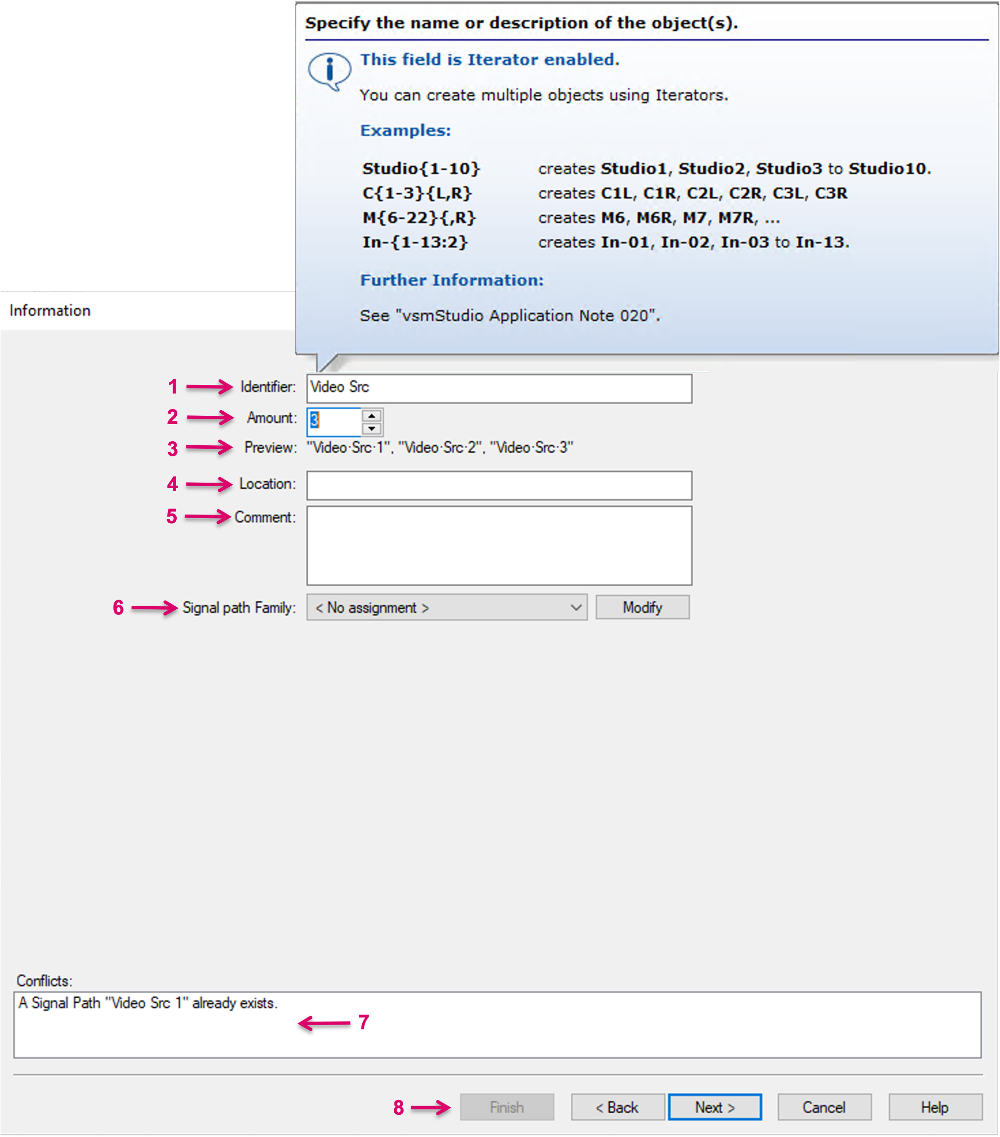
- Set an Identifier name for the new Signal Path(s). Each Signal Path name must be unique within one vsmStudio configuration and is used and displayed as the Identifier label in all other dialogues. Multiple Signal Paths can be created in one go by using Iterators. A pop-up window with examples shows when hovering with the cursor over the Description textbox.
- Alternative to the use of Iterators in the Description field, you can also manually set the Amount of Signal Paths to be created. Consecutive numbers will be automatically added to the set Description name.
- A Preview of the resulting Signal Paths that will be created is displayed.
- Location is an optional, informative text field for the user.
- Comment is an optional, informative text field for the user.
Signal path Family is an optional setting. Mainly informative for the user. Assigning Families also provide the possibility to sort respective Signal Paths in the respective Signal Path list, as well as in Matrix views.
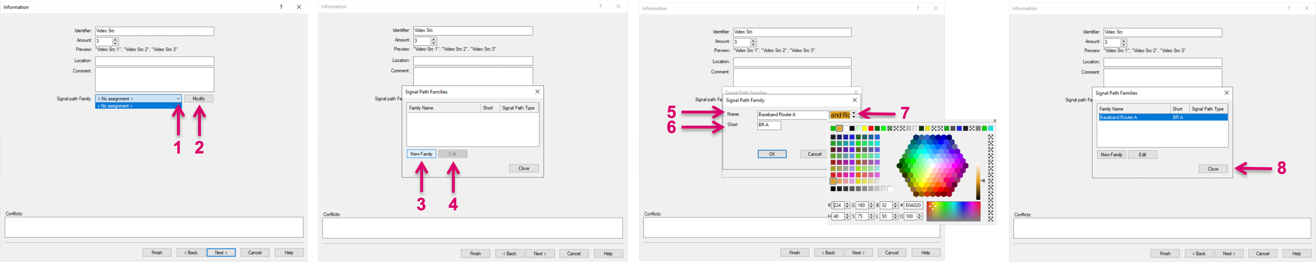
- Select an existing Signal Path Family (1) from the pull-down menu or enter the editor via "Modify" (2).
- Edit an existing Signal Path Family by selecting and clicking "Edit" (3) or create a new one by clicking on "New Family" (4).
- Assign a "Name" (5) and "Short" name (6) for the Signal Path Family and select a background color (lower arrow) and text color (upper arrow) (7). The selected color scheme will only be visible in Matrix views. Confirm with "OK".
- Select the desired Signal Path Family from the list and confirm with close (8).
- Conflicts will show if any of the resulting Descriptions/Identifiers are already existing within the current vsmStudio configuration. Please make sure to correct the Description accordingly until no Conflicts are displayed anymore.
- Navigation controls. Proceed via the respective navigation controls (8).
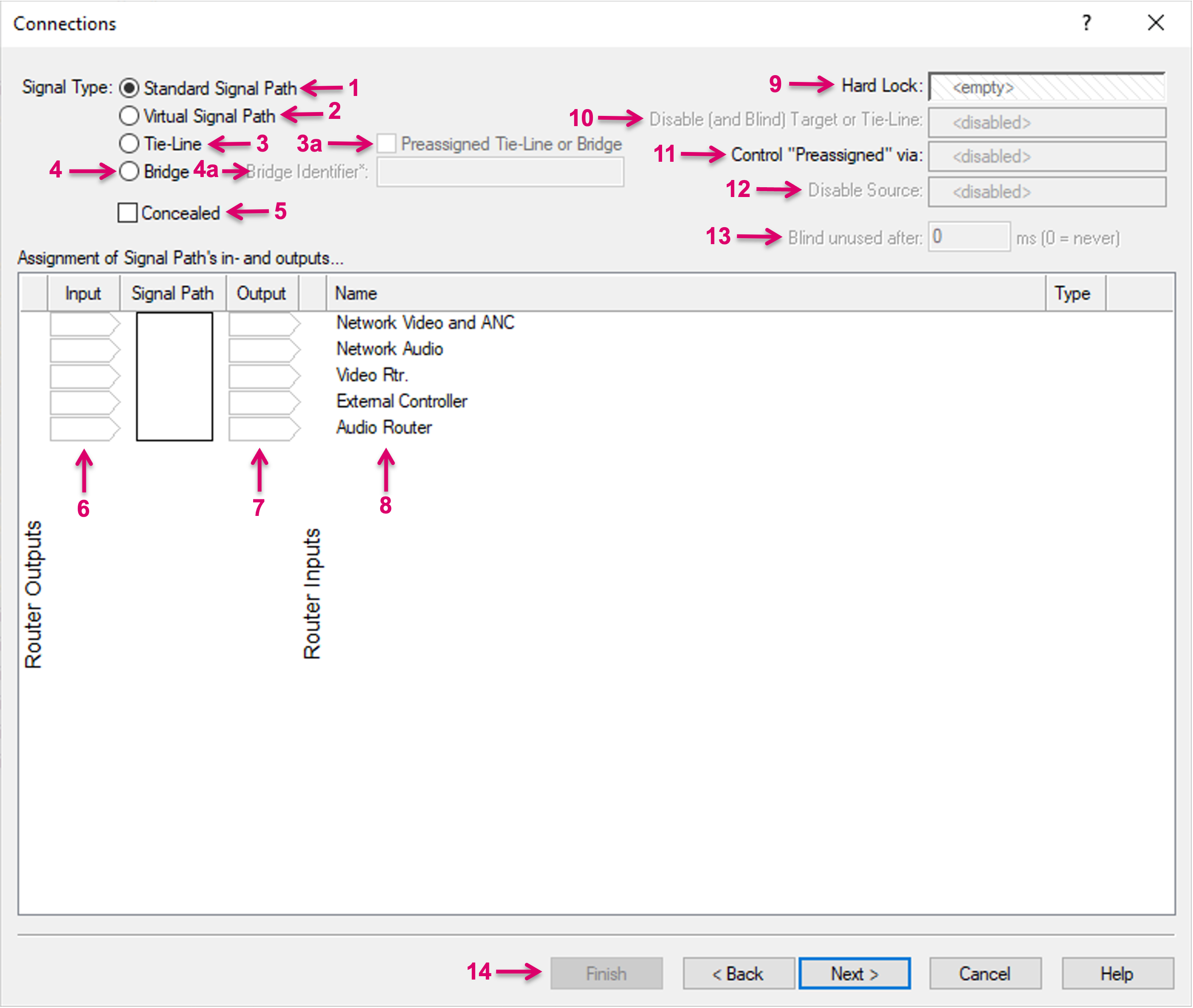
Signal Type Standard Signal Path: As its name implies, this is the standard Signal Path type, to be selected for any physical Signal representation, no matter if baseband or network resource.
Standard Signal Paths may represent a Source, a Target or even both. An example for a Standard Signal Path with Input and Output would be the representation of a loop-through resource like a Framesynchronizer where, the Signal at the output of the Device is, aside the processing, always the same Signal that was fed into the Device.
- Before being able to make any Connections in this view, the respective Layers need to be created and will be listed in this view accordingly.
- When creating a Signal Path representation of a physical crosspoint matrix, the location ID which is selected on the respective layer in vsmStudio, needs to match the appropriate location ID within the device configuration and the respective control protocol.
- When creating Signal Path representations of Network Stream essences, the location ID which is selected on the respective layer in vsmStudio, has no specific hardware dependency and therefore can be freely chosen.
- Click in the respective Input or Output cell of the respective layer row and select the ID to be assigned.
- An assignment can be reverted by selecting the blank field, top left of the selection pop-up, in front of "V".
- When creating multiple Signal Paths in one go, based on the Iterator or Amount setting in the Information view, please note that you only have to select the first ID and the system automatically will allocate the following IDs, up to the total amount of Signal Paths that is required. If the required slots are all or partially already in use, this error will be indicated with a red marker (1). Although you may be able to proceed to the following views, the overall Signal Path creation process cannot be finalized. In this case please first check your configuration and/or your settings in the Information view.
- Optionally you can drop a GPIO trigger for a Signal Path "Hard Lock" (2), "Disable (and Blind) Target or Tie-Line" for Targets (3) or "Disable Source" for Sources (4).
- Proceed to the next step via the respective navigation controls (5).
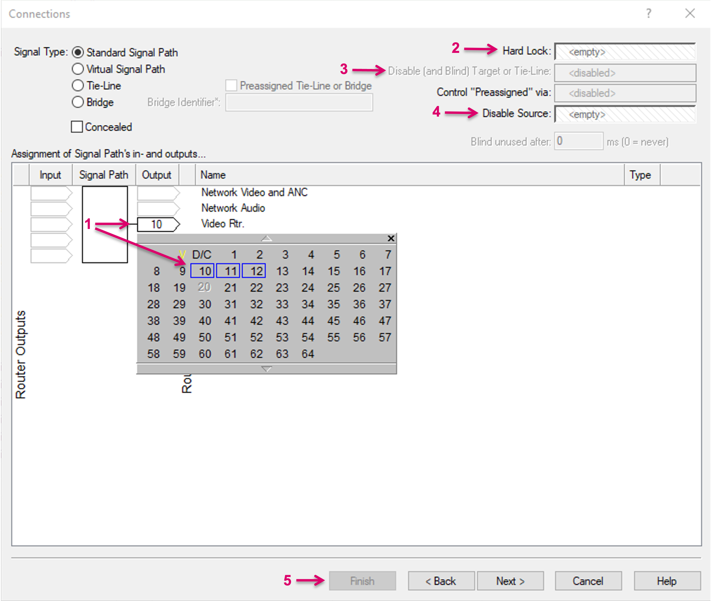

A dedicated "Blind" Signal Path is mandatory to be created for each router layer. On physical routers usually a Video Black or Audio Mute Source signal is defined as "Blind" Signal. On Network Layers, any Source ID may be chosen and defined as "Blind" Signal. Devices that provide an Ember+ interface may provide an internal Disconnect Source. In this case please select "D/C" instead of any other ID from the selection window. In addition the specific "Blind" attribute has to be set in the following "Attributes" window/tab.
Signal Type Virtual Signal Path: Virtual Signal Paths may be used, e.g. as an abstraction layer between physical resources and their production and workflow related usage. Virtual Signal Paths are also a great helper tool for any kind of workflow and business logic, without any dependency on physical resources. Virtual Signal Paths are independent of the size of any physical layer and can even be used across Tie-lines to transfer assignments across physical layers. Virtual Signals with "Blind", or no physical assignment on their Input leg are displayed with square brackets [ ] around the Signal name on Panels and UMDs. "Empty" Virtual Signal Paths cannot be routed to Signal Path Targets.
Virtual Signal Paths are usually set-up with an Input and Output, like a loop-through resource. This allows them to be assigned to physical signals dynamically and basically being "inserted" in any workflow.
- Before being able to make any Connections in this view, any Layer needs to be created, that will be listed in this view accordingly.
- Virtual Signal Paths have no physical dependencies as such, so no specific location ID is required to be configured but only the layer reference, that the Virtual Signal is supposed to be used with in context.
- Click in the respective Input or Output cell of the respective layer row and assign it with "V". The Virtual Signal assignment is indicated with a yellow fill color (1).
- An assignment can be reverted by selecting the blank field, top left of the selection pop-up, in front of "V".
- Optionally you can drop a GPIO trigger for a Signal Path "Hard Lock" (2), "Disable (and Blind) Target or Tie-Line" for the Target leg (3) or "Disable Source" for the Source leg (4).
- Proceed to the next step via the respective navigation controls (5).
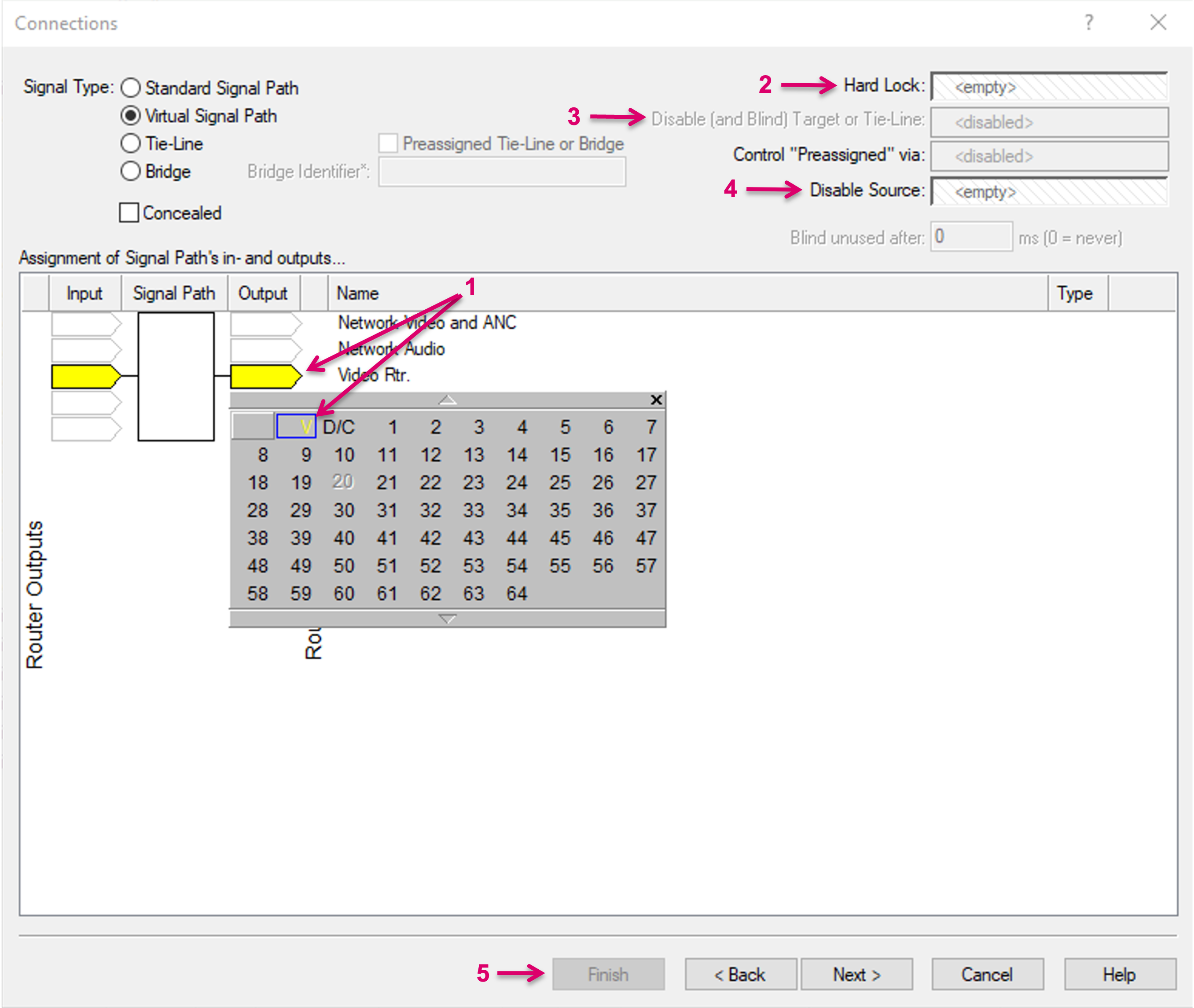

Please note: A direct physical crosspoint has a higher priority than the same assignment routed via a virtual-physical crosspoint. Therefore, a physical crosspoint will always overwrite a virtual-physical crosspoint.
Signal Type Tie-Line: vsmStudio offers an integrated, dynamic Tie-Line management. For switch requests across routers, the dynamic Tie-Line management looks for a free Tie-Line and connects the respective Source and Target accordingly. If the requested Source was already assigned to a Tie-Line based on a previous action, this same Tie-Line will be used and no new Tie-Line will be allocated. Label and Tally information are concealed and transferred through Tie-Lines. In case that all Tie-Lines are already in use, new route requests between the respective layers cannot and will not be executed. On panels this is indicated by a remaining red Source button. Tie-Lines may also be cleared manually by user action via a panel.
Instead of a dynamic usage, the Preassigned Tie-Line or Bridge option (on Source side) allows specific Source Signals being statically available via Tie-Line or Bridge at any time, while their usage on targets is still managed on request by VSM. The pre-assignment of Tie-Lines and Bridges may be considered a preparing setup task. Preassigned Tie-Lines and Bridges shall not be used as dynamically switched Targets in an operational workflow. To set up a Preassigned Tie-Line or Bridge, the respective attribute has to be checked (3a).
Tie-Lines represent a physical connection between two layers, e.g. two Routers. Therefore they have an Input leg on one layer and the Output leg on a different layer.
- Before being able to make any Connections in this view, the respective Layers need to be created and will be listed in this view accordingly.
- The location ID, which is selected on the respective layer in vsmStudio, needs to match the appropriate location ID within the device configuration and the respective control protocol.
- Click in the respective Input (1) or Output (2) cell of the respective layer row and select the ID to be assigned.
- An assignment can be reverted by selecting the blank field, top left of the selection pop-up, in front of "V".
- When creating multiple Tie-Lines in one go, based on the Iterator or Amount setting in the Information view, please note that you only have to select the first ID and the system automatically will allocate the following IDs, up to the total amount of Tie-Lines that is required. If the required slots are all or partially already in use, this error will be indicated with a red marker. Although you may be able to proceed to the following views, the overall Tie-Line creation process cannot be finalized. In this case please first check your configuration and/or your settings in the Information view.
- For Tie-Lines only, Input and Output cells will be marked with a purple border color.
- Optionally you can drop a GPIO trigger for the "Disable (and Blind) Target or Tie-Line" for Targets (3) function and/or set a time for "Blind unused after" (4).
- Optionally Tie-Lines can be preassigned (5) to be statically routed. Tie-Lines configured this way, will not be managed dynamically by the system. Once this option is selected, this setting can also be controlled via GPI (6).
- Proceed to the next step via the respective navigation controls (7).
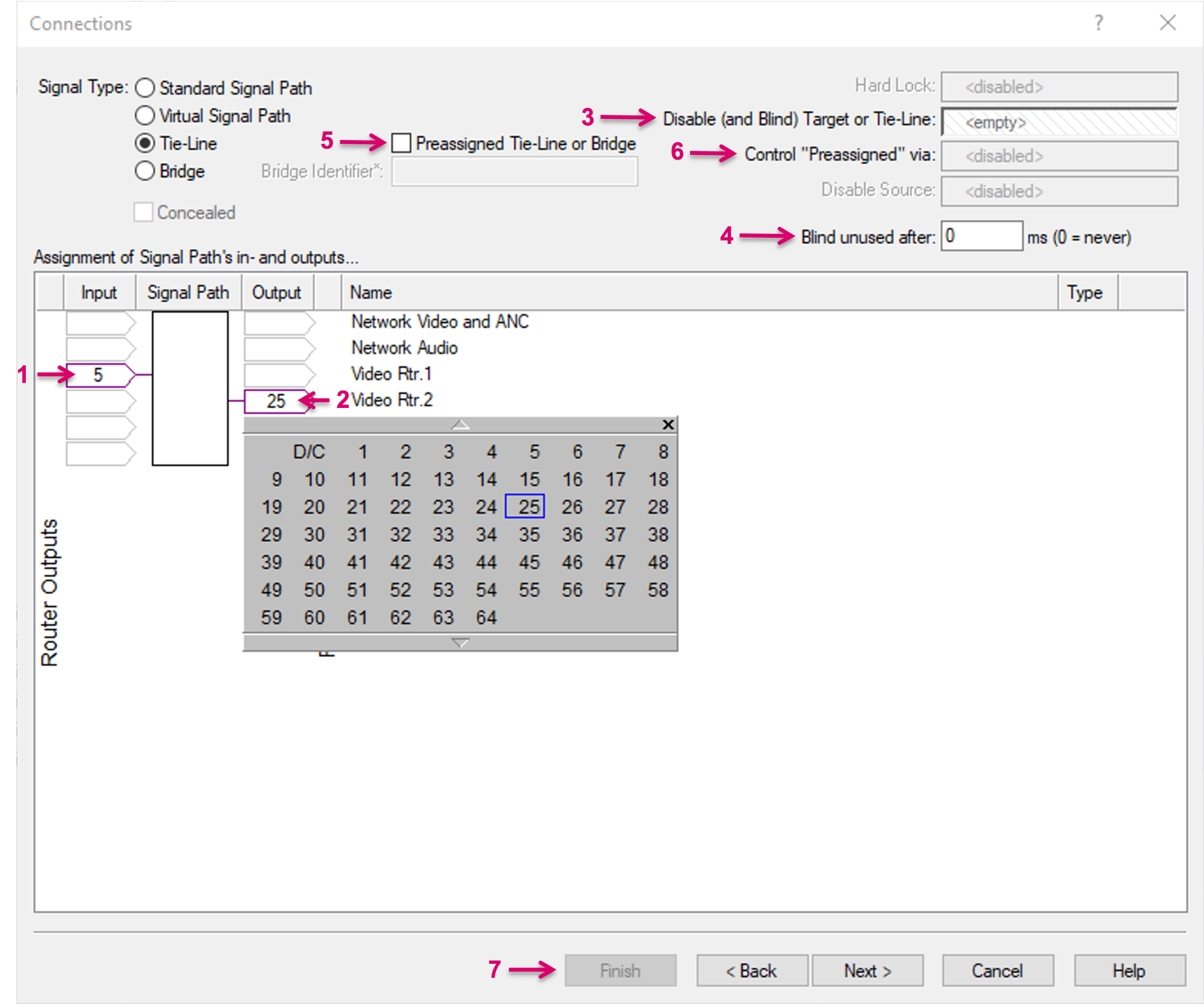
A dedicated "Blind" Signal Path is mandatory to be created for each router layer. On physical routers usually a Video Black or Audio Mute Source signal is defined as "Blind" Signal. On Network Layers, any Source ID may be chosen and defined as "Blind" Signal. Devices that provide an Ember+ interface may provide an internal Disconnect Source. In this case please select "D/C" instead of any other ID from the selection window. In addition the specific "Blind" attribute has to be set in the following "Attributes" window/tab. Without "Blind" signal, Tie-Lines cannot be cleared and the status of the Tie-Line with respect to its recipients cannot be reported properly!
Please note that dynamic Tie-Line Targets shall not be switched directly, e.g. via a Matrix view. The system prevents this action as the allocation is exclusively handled by VSM.
- Signal Type Bridge: Future Option including the additional attribute Bridge Identifier (4a).
- Concealed: If the option Concealed is checked, the label of this specific Signal Path will not be displayed as Source of Target on Panels and UMDs. Instead, the label of the preceding Source in the Signal Path chain will be displayed. This option is applicable for Signal Paths with Source and Target side.
- Signal Path Input: Shows the Physical location ID on the respective layer. The Input of a Device/Resource = A Target from a Router perspective and in vsmStudio.
- Signal Path Output: Shows the Physical location ID on the respective layer. The Output of a Device/Resource = A Source from a Router perspective and in vsmStudio.
- Layer Name: Shows the respective layer name, the Signal Path is assigned to.
- Hard Lock: Applicable for Target Signal Paths only. A GPIO can be dropped into the drop-zone. As long as this condition is true, the respective Target Signal Path will be operationally locked to its current Source and cannot be switched anymore. Can only be unlocked again if Hard Lock trigger gets false.
- Disable (and Blind) Target or Tie-Line: Applicable for Target Signal Paths and Tielines only. A GPIO can be dropped into the drop-zone. Once this condition becomes true, the respective Target Signal Path will be automatically switched to its layers Blind Source, will be operationally locked and cannot be switched anymore. Can only be unlocked again if the trigger gets false.
- Control "Preassigned" via: Once the Preassigned option is selected, this setting can be used to control this option via GPI.
- Disable Source: Applicable for Source Signal Paths only. A GPIO can be dropped into the drop-zone. As long as this condition is true, the respective Source Signal Path will be operationally locked and cannot be switched anymore. Existing Crosspoints containing this source will remain in place and functional until switched. Can only be unlocked again if the trigger gets false.
- Blind unused after: Related to Tie-Lines only. If a Tie-Line was used by the system once, the respective Source assignment will remain in place. Even if no Target requests the specific source anymore. Aside of the option to manually free up Tie-Lines via user panels, The "Blind unused after" function allows for a timed, automated clean-up where the Tie-Line would get freed up if not used for the specified timeframe..
- Navigation controls. Proceed to the next step with "Next" or in Edit mode proceed with "Cancel", "Apply" or "OK".
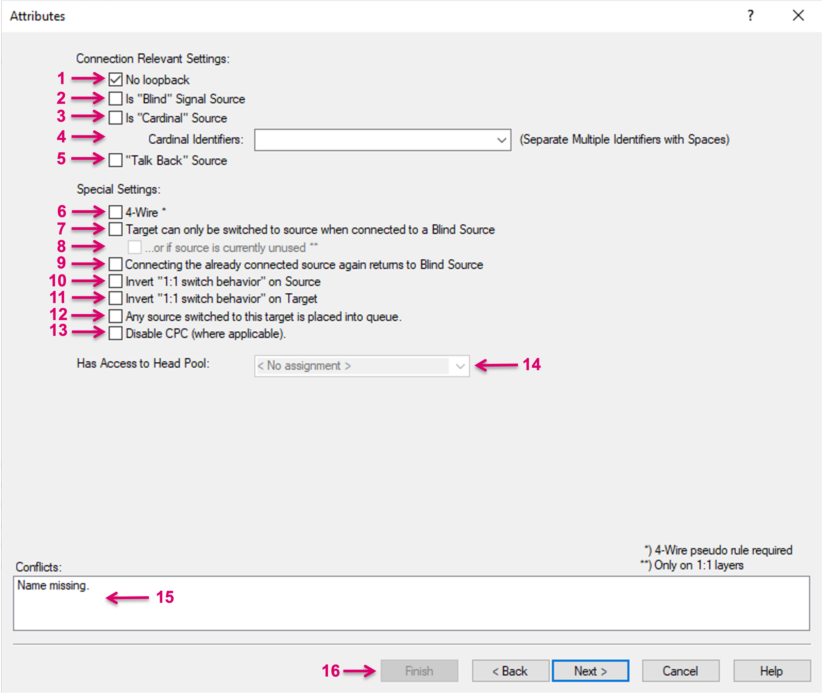
- No loopback: This attribute is checked by default. It prevents that this Signal Path is switched onto itself.
- Is "Blind" Signal Source: A dedicated "Blind" Signal Path is mandatory to be created for each router layer. On physical routers usually a Video Black or Audio Mute Source signal is defined as "Blind" Signal. On Network Layers, any Source ID may be chosen and defined as "Blind" Signal. In addition, this attribute has to be set. One "Blind" Signal per layer only!
- Is "Cardinal" Source: If this attribute is set on a Signal Path Source allows the system to identify and locate this Source via "Dynamic Attachment Scripts". The cardinal attribute is used to mark signals that have a special significance to the workflow making it easier to locate them with DAS.
- Cardinal Identifiers: An optional attribute that can be used in combination with the Is "Cardinal" Source attribute for even more granular system identification via "Dynamic Attachment Scripts". Multiple Identifiers are possible to be set for the same Signal Path that then allow DAS to find this Source by any of its defined Cardinal Identifiers.
- "Talk Back" Source: If this attribute is set on a Signal Path Source it allows to toggle between this and the previous Source of the selected Target, by simply selecting this "Talk Back" Source Source again.
- 4-Wire*: This attribute requires in addition a specific Pseudo Device rule (Ports) and, in combination, allows for a 4-Wire switching behavior.
- Check this box to define that the Signal Path Target can only be switched to source when it is currently connected to a Blind Source. Only applicable on Signal Path Targets.
- ...or if Source is currently unused**. An optional attribute that can be used in combination with Target can only be switched to source when connected to a Blind Source. Only applicable on Signal Path Targets that are located on 1:1 layers.
- Connecting the already connected source again returns to Blind Source allows to toggle between a Source and the defined Blind Source.
- Invert "1:1 switch behavior" on Source: This attribute has to be used in combination with Invert "1:1 switch behavior" on Target. In combination, all Signal Path marked with this attribute will switch and behave like resources on an 1:1 router.
- Invert "1:1 switch behavior" on Target: This attribute has to be used in combination with Invert "1:1 switch behavior" on Source. In combination, all Signal Paths marked with this attribute will switch and behave like resources on an 1:1 router.
- Any source switched to this target is placed into queue: This attribute is required on any Signal Path Target that is intended to be used in combination with the Panel function "Queue Control". Only applicable on Signal Path Targets.
- Disable CPC (where applicable): Only applicable on Network Signal Path Targets. This attribute may be used if it is intended that the respective Target can be switched from a 3rd control instance or within an end-device itself.
- Has Access to Head Pool: Only applicable on Signal Path Targets and in combination with the "Distributed Multi Viewer" module. Head Pools have to be created beforehand in the "Monitor Management" section and then be selected accordingly via the drop-down menu.
- Conflicts: will show if any of the resulting Descriptions/Identifiers are already existing within the current vsmStudio configuration. Please make sure to correct the Description accordingly until no Conflicts are displayed anymore.
- Navigation controls.
This section contains all specific settings to configure Network Source Signal Paths.

- The window is divided in two sides, one for Red Network Information Provision and one for Blue Network Information Provision. Dependent on the Network system and controlled device, even in -7 there may be no need to enter any separate information on the Blue Network Information Provision. For instance, if the primary and secondary Stream information may be embedded within onea single SDP Parameter.
You can drag the SDP from Device from the respective node in the Gadget tree and and drop it here.

- Optionally the Essence pre Augment Filter settings can be set. Please refer to the respective Media Essence Filter documentation for further details.
- Alternative to the direct assignment of a SDP parameter, a valid SDP by User can be manually pasted.
- This section may show the SDP by User or SDP information provided via the SDP from Device.
- If the connected device does not provide any SDP information but only separate Network information, here you can either drop the respective Parameter or enter a static Host Address.
- If the connected device does not provide any SDP information but only separate Network information, here you can either drop the respective Parameter or enter a static Multicast Address.
- If the connected device does not provide any SDP information but only separate Network information, here you can either drop the respective Parameter or enter a static Multicast Port.
- For SDN application only, the Network Bandwidth is specified here. Please refer to the specific Arista CVX interface documentation for further details.
- For SDN application only, the Switch is specified here. Please refer to the specific Arista CVX interface documentation for further details.
- For SDN application only, the Interface (Switch Port) is specified here. Please refer to the specific Arista CVX interface documentation for further details.
- For SDN application only. The Chassis ID, as provided via the online Arista CVX will be displayed here. Please refer to the specific Arista CVX interface documentation for further details.
- For SDN application only. The Port ID, as provided via the online Arista CVX will be displayed here. Please refer to the specific Arista CVX interface documentation for further details.
- For SDN application only. Here you can define if the controlled resource is "Moveable". Please refer to the specific Arista CVX interface documentation for further details.
- Navigation controls.
A Network Source without static or parameter-assigned SDP is not supported. Otherwise, e.g. in SDN environment and in combination with an assigned Switch interface, it may cause unexpected and, in the worst case, disruptive routing behavior.
This section contains all specific settings to configure Network Target Signal Paths.
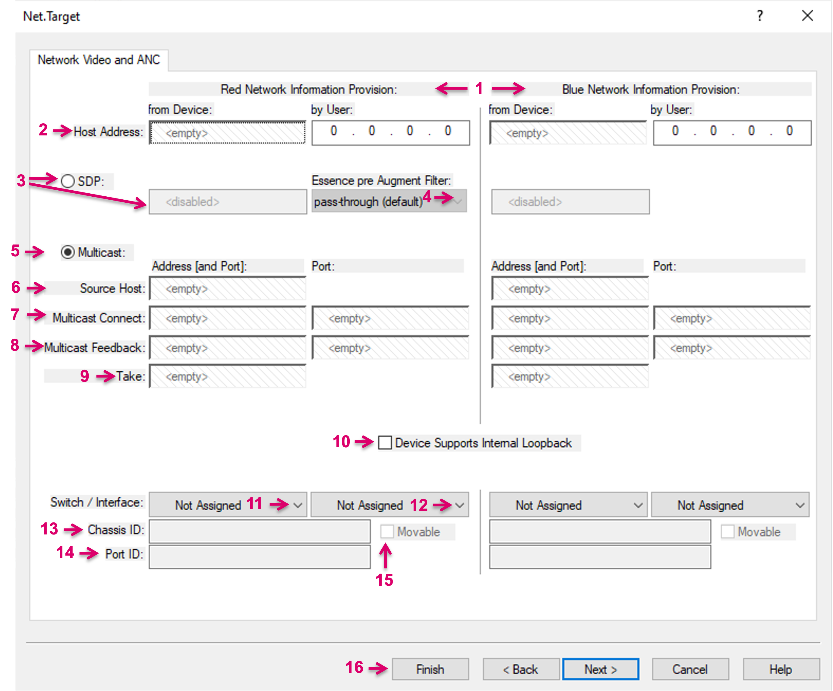
- The window is divided in two sides, one for Red Network Information Provision and one for Blue Network Information Provision. Dependent on the Network system and controlled device, even in -7 there may be no need to enter any separate information on the Blue Network Information Provision. For instance, if the primary and secondary Stream information may be embedded within one single SDP Parameter.
- If the connected device supports a direct SDP Parameter to receive Stream data, but only separate Network information, here you can either drop the respective Parameter or enter a static Host Address.
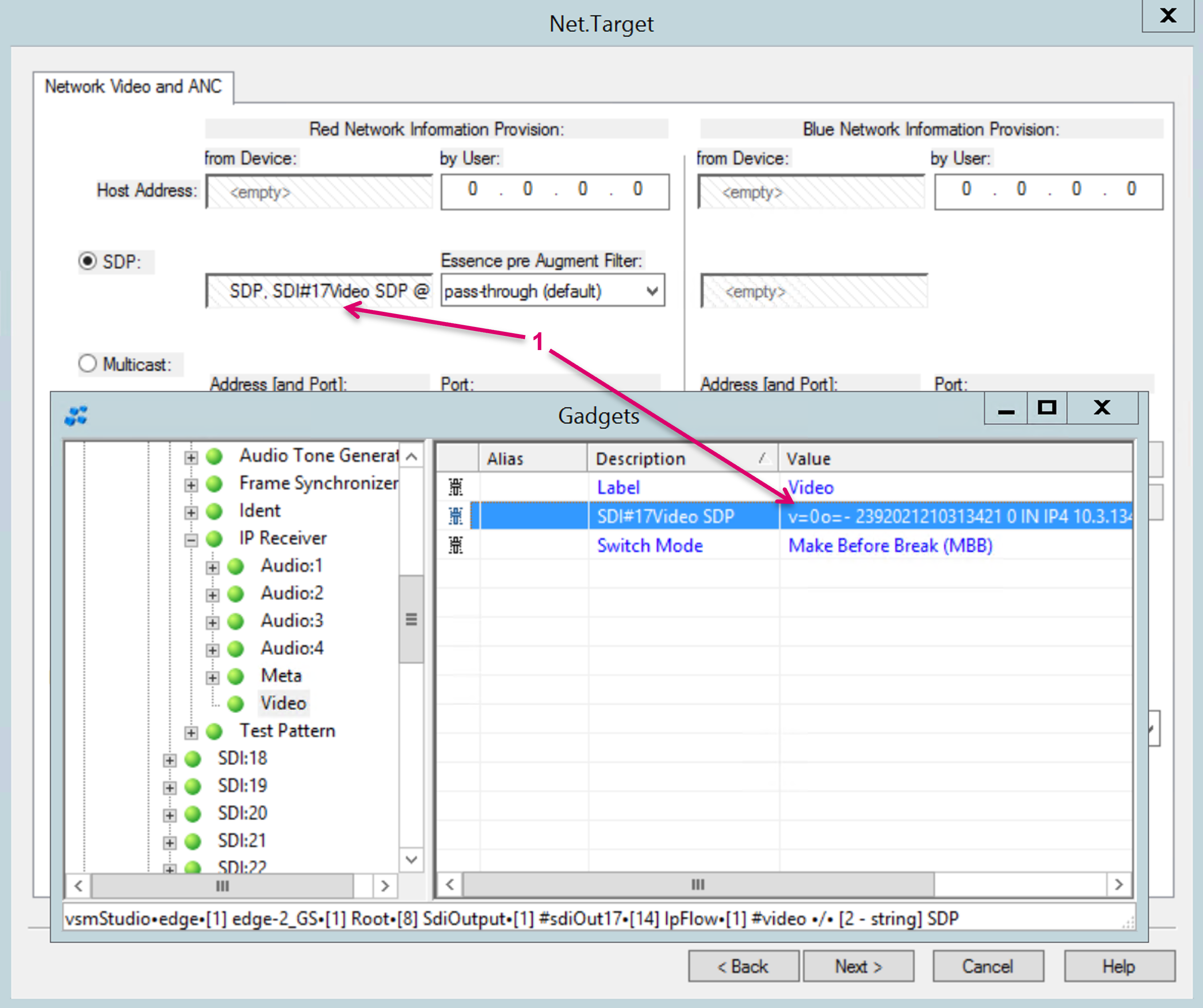
If the connected device supports a direct SDP Parameter to receive Stream data, select the operational mode SDP, then drag the SDP parameter from the respective node in the Gadget tree and and drop it here (1).
- Optionally the Essence pre Augment Filter settings can be set. Please refer to the respective Media Essence Filter documentation for further details.
- If the connected device does not support a direct SDP Parameter to receive Stream data but separate Stream information, select the operational mode Multicast.
- If the connected device does not support a direct SDP Parameter to receive Stream data but a Source Host parameter, you can drag this parameter from the respective node in the Gadget tree and and drop it here.
- If the connected device does not support a direct SDP Parameter to receive Stream data but a Multicast Connect IP and Port parameter, you can drag these parameters from the respective node in the Gadget tree and and drop it here.
- If the connected device does not support a direct SDP Parameter to receive Stream data but a Multicast Feedback IP and Port parameter, you can drag these parameters from the respective node in the Gadget tree and and drop it here.
- If the connected device does support a Take parameter, you can drag this parameter from the respective node in the Gadget tree and and drop it here.
- If the connected Device Supports Internal Loopback, please check this option accordingly.
- For SDN application only, the Switch is specified here. Please refer to the specific Arista CVX interface documentation for further details.
- For SDN application only, the Interface (Switch Port) is specified here. Please refer to the specific Arista CVX interface documentation for further details.
- For SDN application only. The Chassis ID, as provided via the online Arista CVX will be displayed here. Please refer to the specific Arista CVX interface documentation for further details.
- For SDN application only. The Port ID, as provided via the online Arista CVX will be displayed here. Please refer to the specific Arista CVX interface documentation for further details.
- For SDN application only. Here you can define if the controlled resource is "Moveable". Please refer to the specific Arista CVX interface documentation for further details.
- Navigation controls.
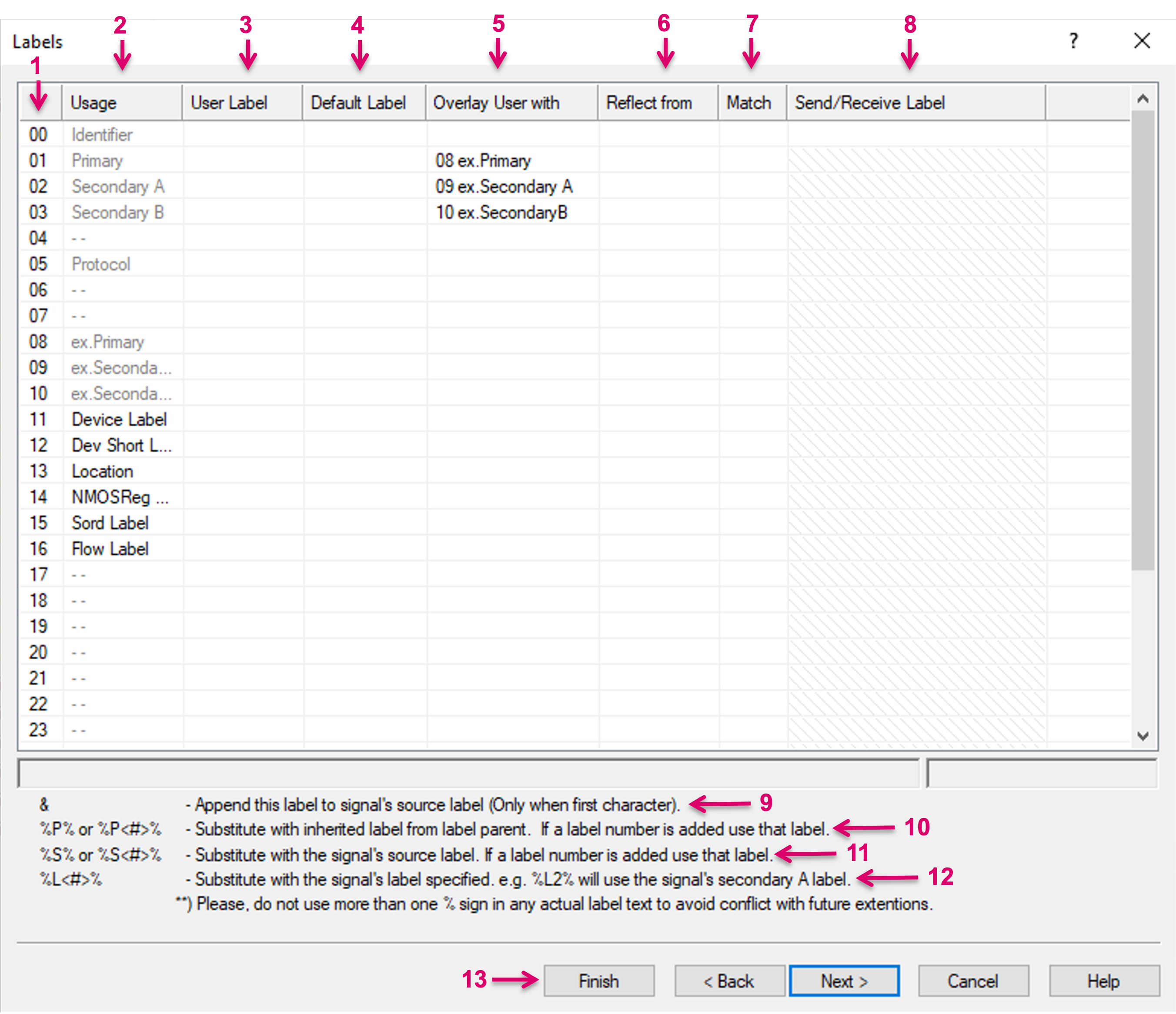
- Label level ID: Up to 32 Label levels may be used per Signal Path. ID08, 09 and 10 are reserved to receive Labels from external, e.g. via Probel sw-p-08 protocol.
- ID00 is dedicated to the unique Signal Path Label.
- ID01 is the Primary label displayed on Panel buttons and UMDs. If no Label is set for ID01 Primary, the Identifier will be shown on Panel buttons and UMDs.
- Usage level: Name to indicate the specific Usage per Label level. All names, except Identifier, are customizable. "Identifier" is locked and dedicated to the unique Signal Path Label and identity. All (and only) labeled Usage levels are displayed as Columns in Signal Path list and are selectable in any Displayed-Label-Selector drop-down menu within other views.
- User Label: Customizable Label, that can be set in this view, via the Signal Path list and also via Panels. The User Label is displayed on Panel buttons and UMDs with a higher priority than the Default Label. Since the Label for ID00 Identifier has to be unique and identifies the Signal Path as such, it is static and can only be set in the Information tab.
- Default Label: Customizable Label, that can be set in this view and via the Signal Path list. The Default Label is displayed on Panel buttons and UMDs with a lower priority than the User Label. Since the Label for ID00 Identifier has to be unique and identifies the Signal Path as such, it is static and can only be set via the Information tab.
- Overlay User with: In this cells, any of the 32 Usage levels other than the currently edited, can be selected via drop-down menu. The User Label content of the so selected Usage level will then overlay the User and Default Label of the currently edited Usage level.
Reflect from: This feature may be used on Signal path Sources. In this cells, any of the 32 Usage levels can be selected via drop-down menu (1). The respective local Source User Label will be reflected from the currently connected Signal Path Target and replaced accordingly, if the Label cells on the respective Usage level on the Target side are not blank.
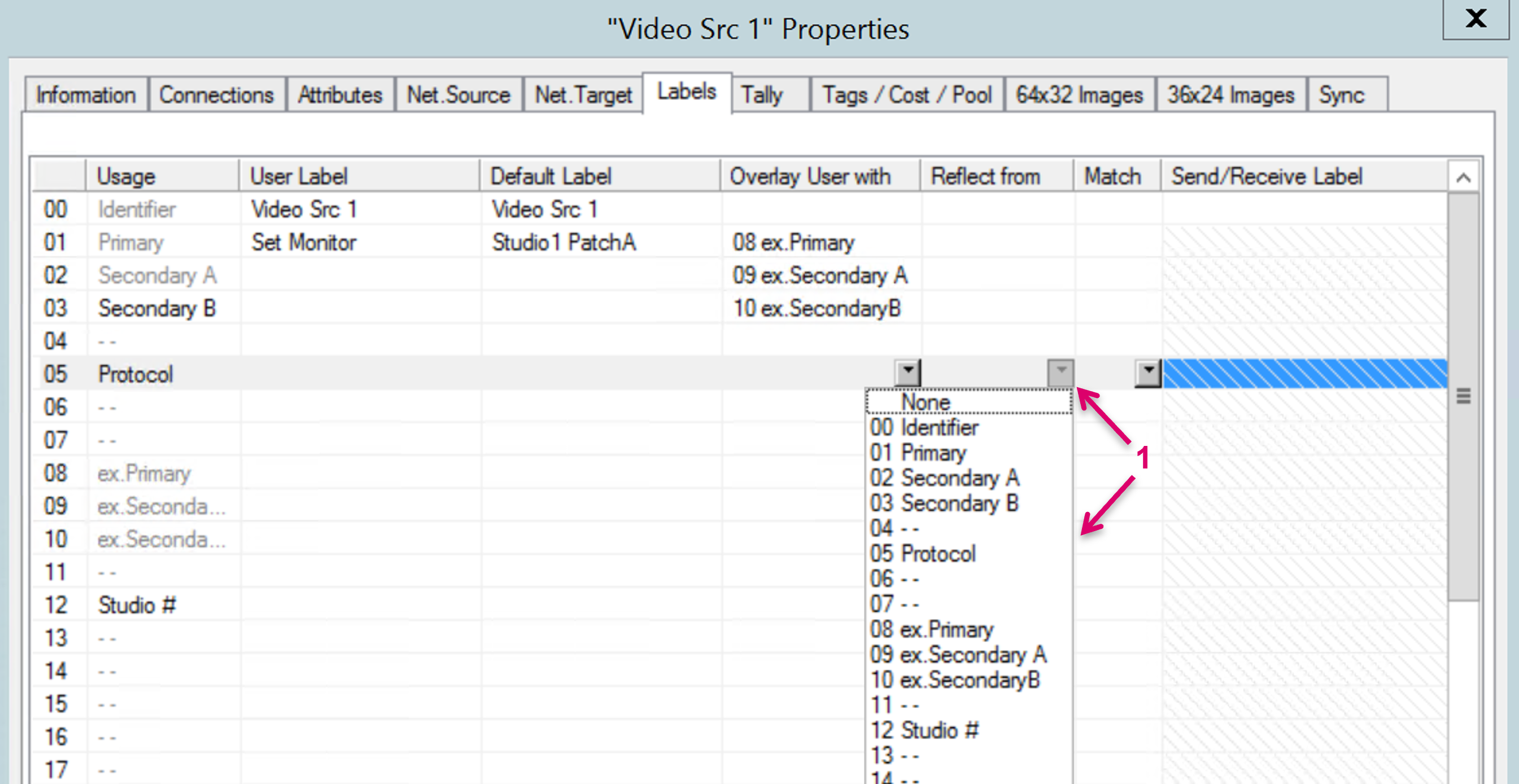
Match: This feature may or may not be used on Signal Path Targets in combination with the Reflect from feature on Signal Path Sources. In these cells you can select the following conditions via drop-down menu (1) that may affect the switching behavior.
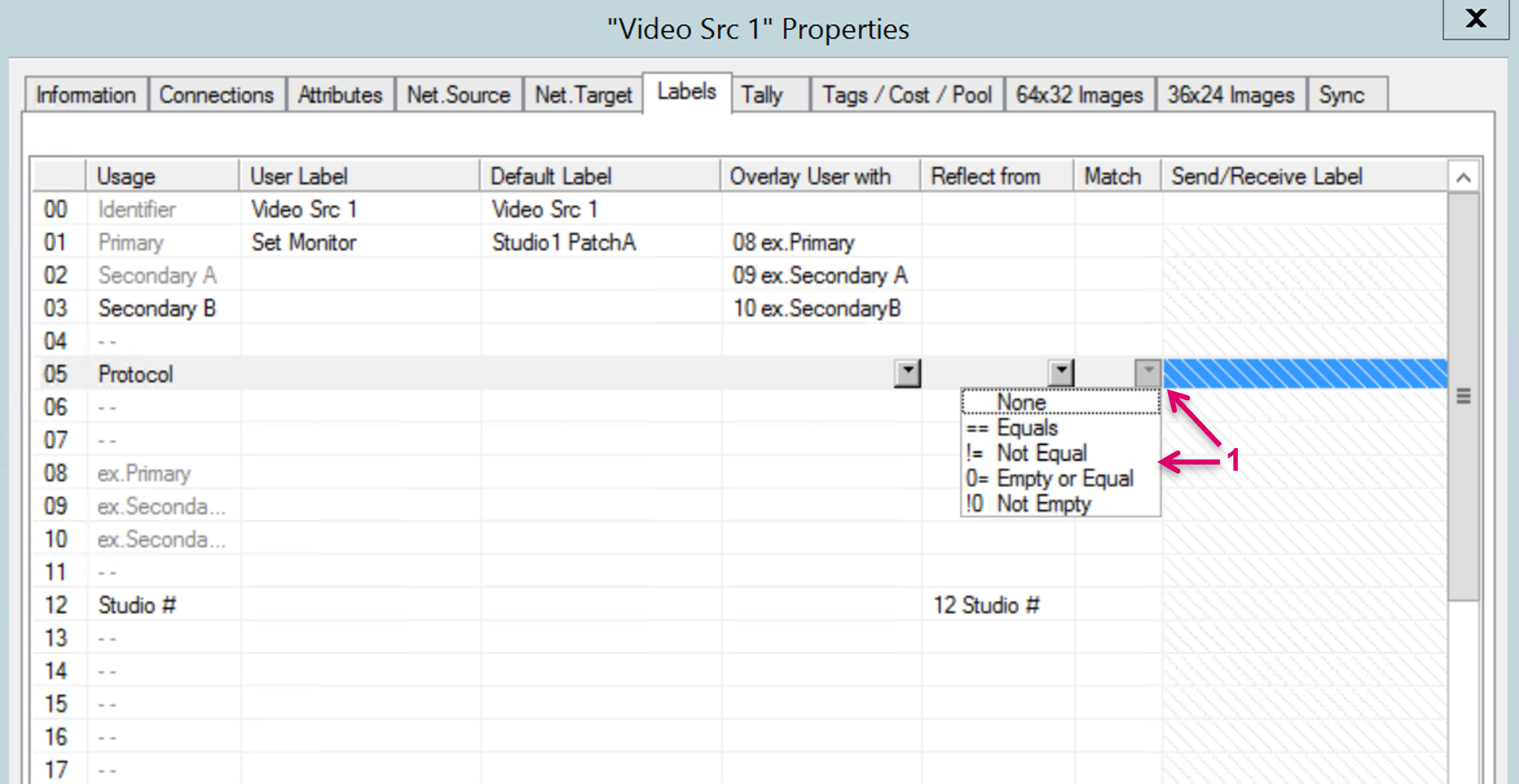
- == Equals: The selected Signal Path Target will only be connected with Signal Path Sources where the Label on the respective Usage level is existing and the same.
- != Not Equal: The selected Signal Path Target will only be connected with Signal Path Sources where the Label on the respective Usage level is blank or not the same.
- 0= Empty or Equal: The selected Signal Path Target will only be connected with Signal Path Sources where the Label on the respective Usage level is existing and the same.
!0 Not Empty: The selected Signal Path Target will only be connected with Signal Path Sources where the Label on the respective Usage level is not blank.
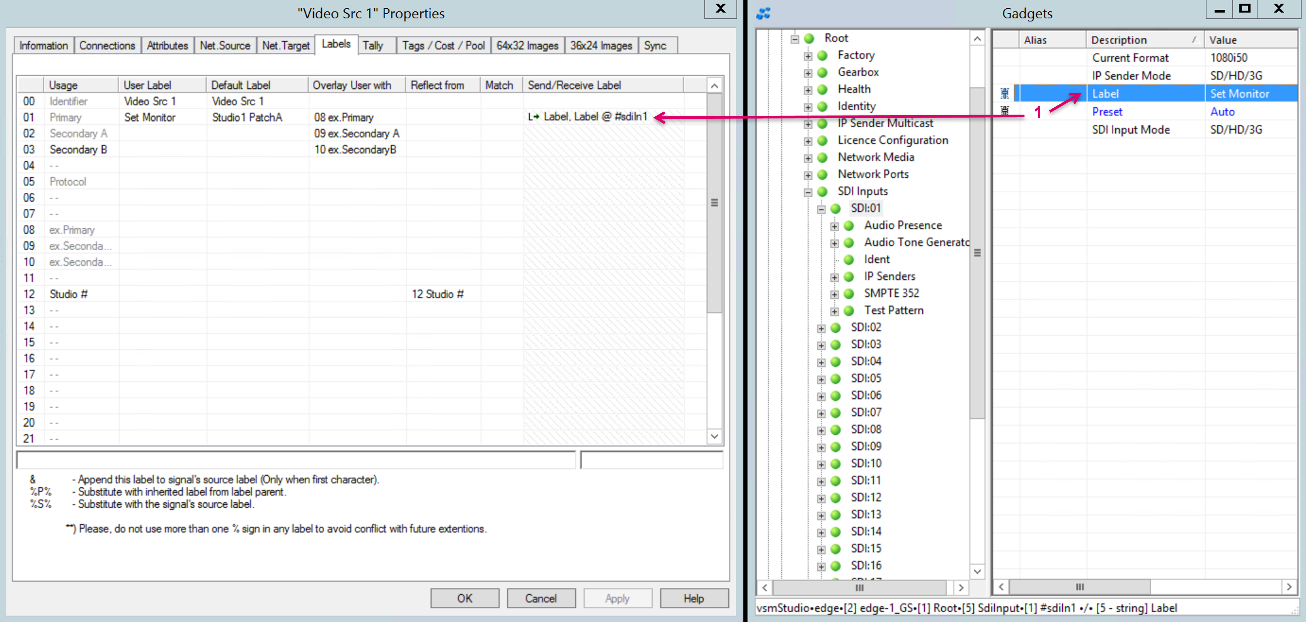
Send/Receive Label: A Gadget Parameter from the "Gadgets" view may be dropped into the cells of this column, to write the User label from external or send the User label to an external device via protocol (1).
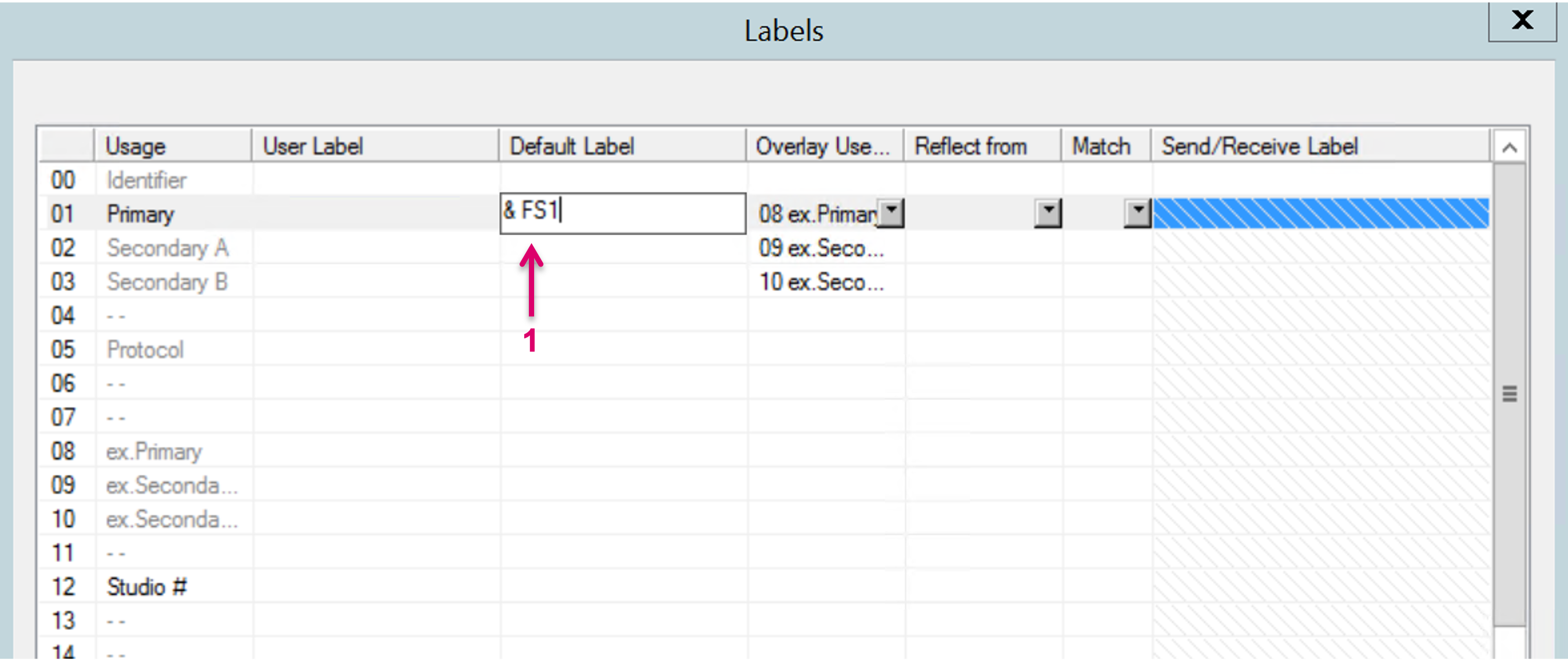
Special character appendix &: If the assigned Label is started with this character (1), the system will Append this label to signal's source label (Only when first character). The resulting Label text is only visible and displayed on Panel buttons and UMDs, not within Matrix or Signal Path views.
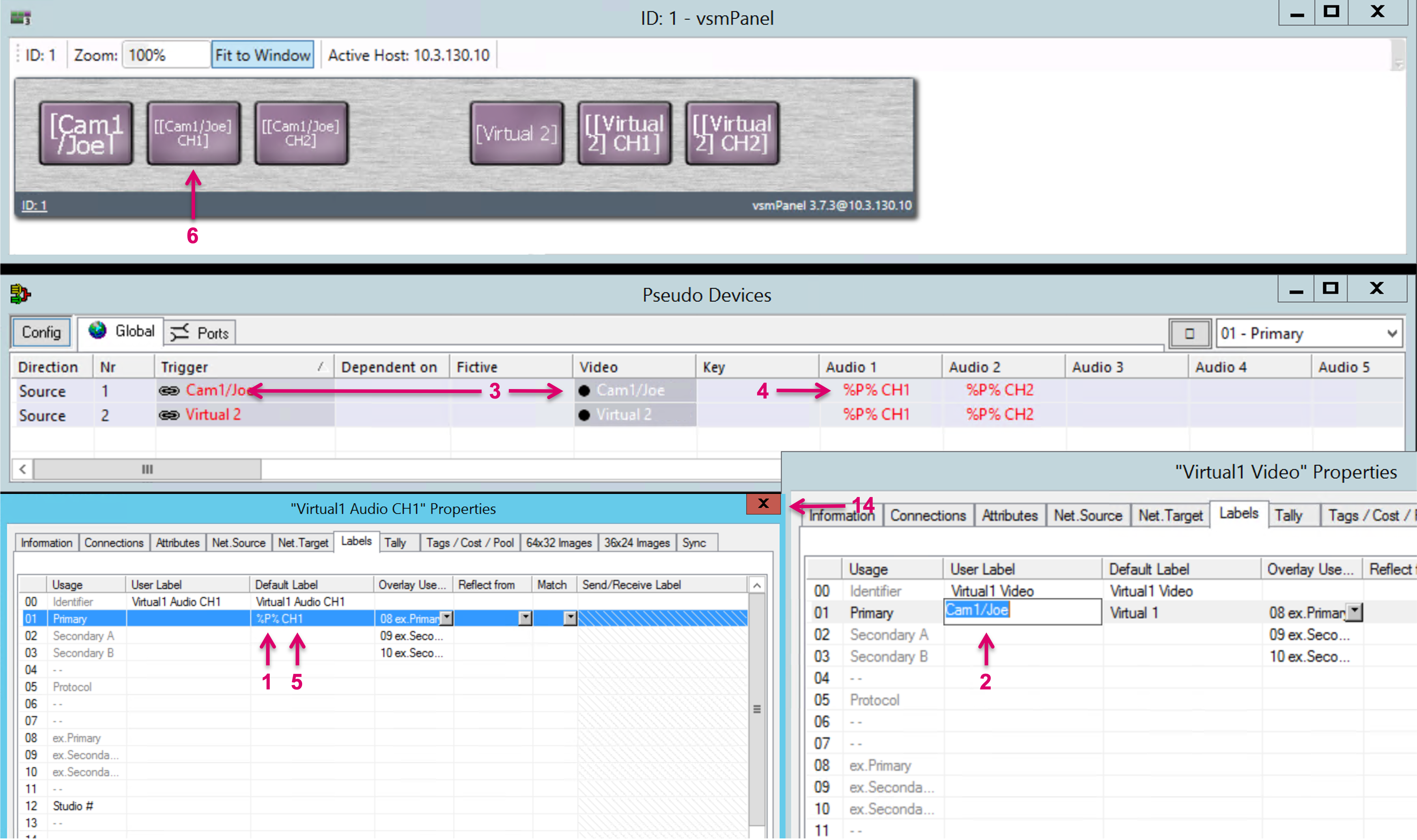
Special character set appendix %P% or %P<#>%: By typing this character set in any of the Label cells (1), the respective label will be Substituted with inherited label from label parent (2). If a label number is added, this respective label will be used. A label parent is defined by the Trigger signal of a Pseudo Device rule (3), the children are the respective attachments (4). Adding additional text behind this character set is still possible (5), e.g. to identify Audio Channel numbering added to the Label inherited from a Video Parent. The resulting Label text is only visible and displayed on Panel buttons (6) and UMDs, not within Matrix or Signal Path views.
- Special character set appendix %S% or %S<#>%: By writing this character set in any of the Label cells, the respective label will be Substituted with the signal's source label. If a label number is added, this respective label will be used. Adding additional text behind this character set is still possible, e.g. to display the current Source label in combination with the local Target Label. The resulting Label text is only visible and displayed on Panel buttons and UMDs, not within Matrix or Signal Path views.
- Special character set appendix %L<#>%: By writing this character set in any of the Label cells, the respective label will be Substituted with the signal's label specified. E.g., %L2% will use the Signal's "Secondary A" label.
- Navigation controls. Proceed to the next step with "Next" or in Edit mode proceed with "Cancel", "Apply" or "OK".
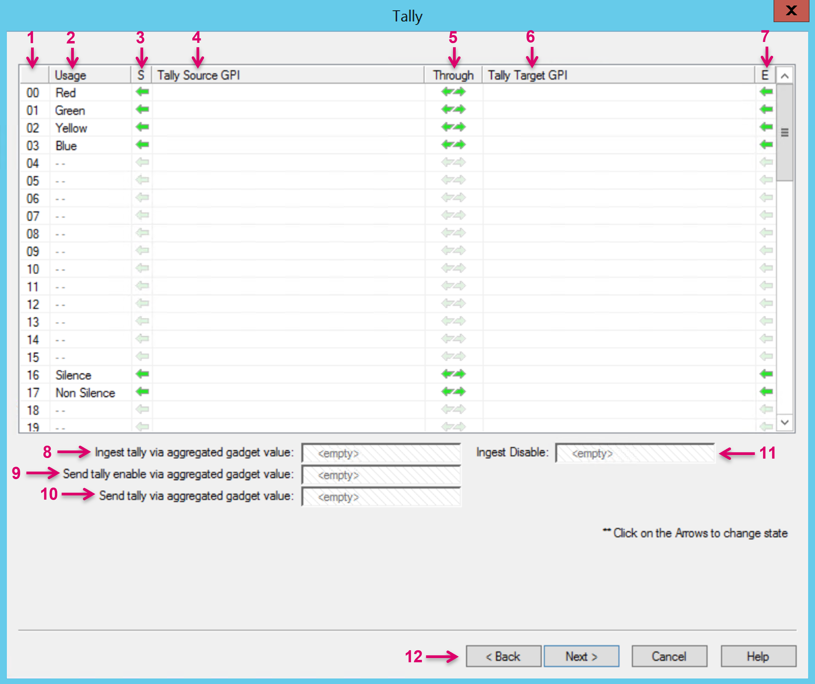
- Tally level ID: Up to 64 Tally levels may be used per Signal Path. Some IDs are by default used for specific system Tallies.
- The column Usage contains descriptive naming for the respective Usage per Tally level. All names are customizable. All (and only) labeled Usage levels are displayed and selectable in any Tally-Selector drop-down menu within other views.
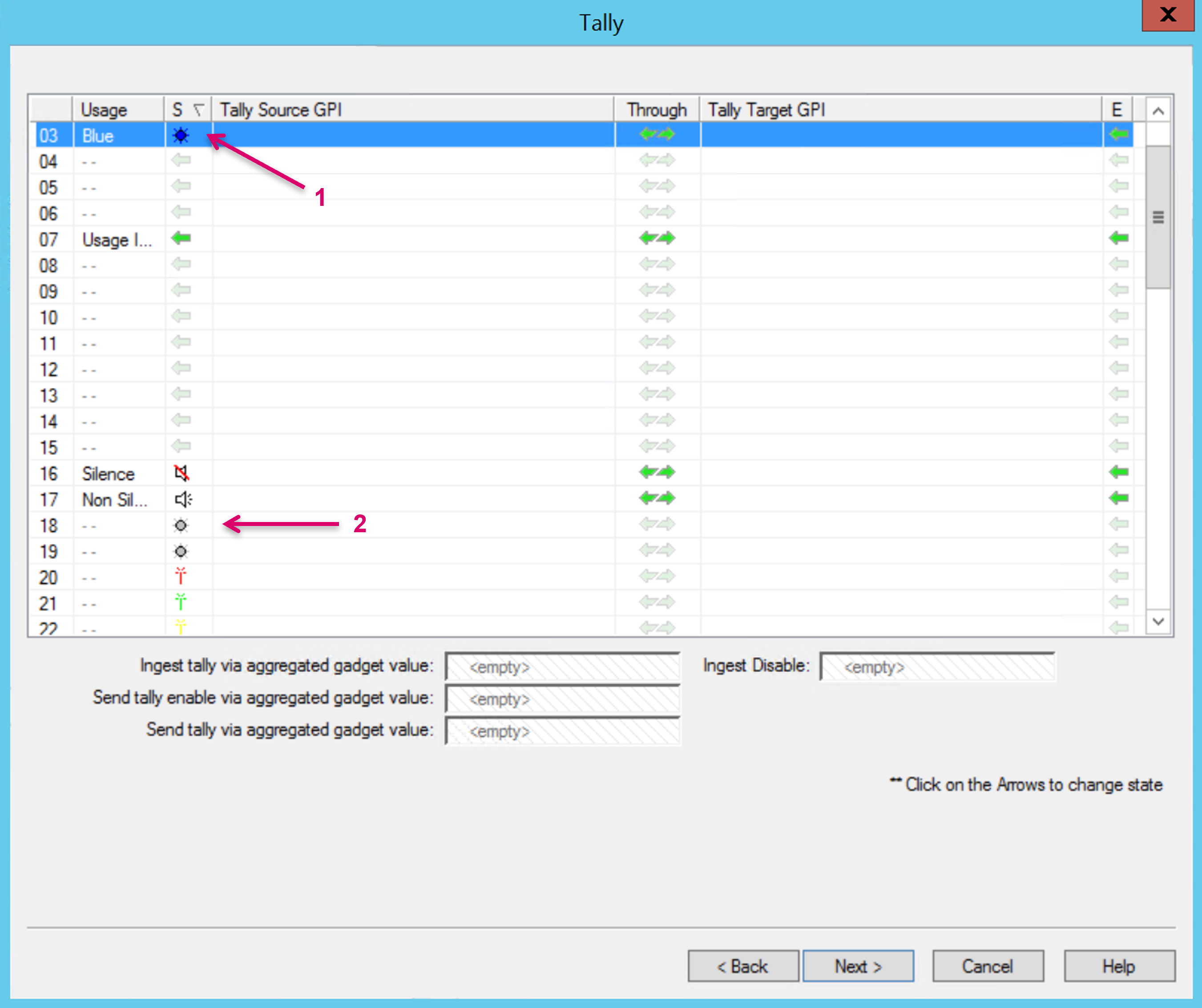
Via the arrow icon in cells of the S (Static) column, a static Tally can be assigned per Tally level. Only applicable on Signal Path Targets. The so assigned Tally level of a Signal Path Target will act as the respective Tally-source for any connected Signal Path Source. The icons displayed in this column may also be displayed in matrix views for any Signal Path that is Tally-source, or affected by an active Tally.
- Click on the green arrow icon to assign the static Tally. The respective icon will appear (1).
- Some Tally levels show static icons for dedicated usage, like the Antenna or Speaker icon (2). This does not limit these Tally levels to this specific usage, they can be used for other applications as well.
- Some Tally levels have no specific color differentiation and are displayed as grey led icon only (2).
- All icons and their respective color per Tally level are fixed and cannot be modified.
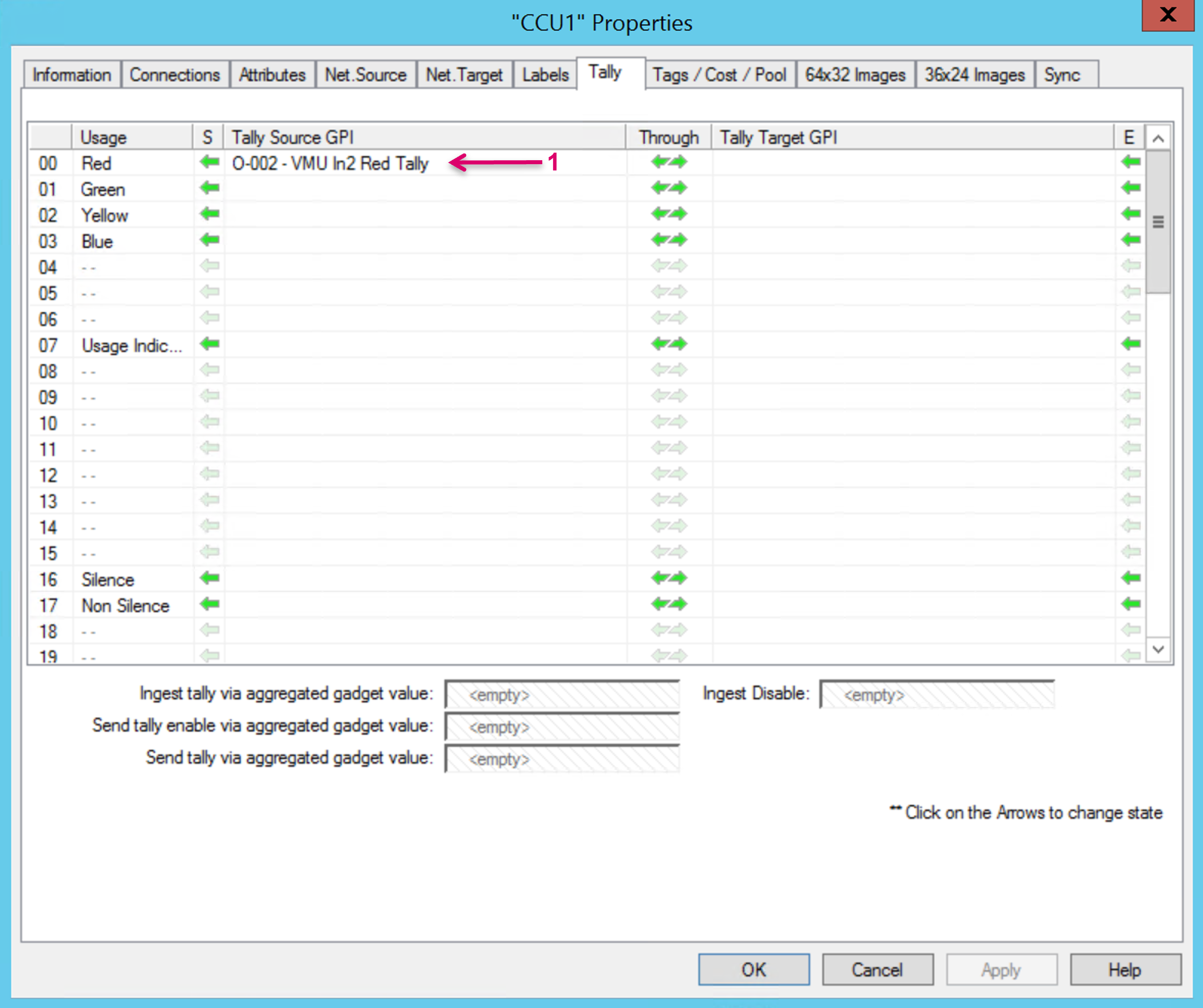
Tally Source GPI: Only applicable on Signal Path Sources. If a GPI or GPO was assigned to this Signal Path Source, the respective GPIO will be displayed here (1). The cells in this column are display only, no assignments can be made in this view. If you want to assign a GPIO to a Signal Path please refer to the GPIO documentation.
- Via the arrow icons in the cells of the Through column, it can be specified if System Tally is passed through.
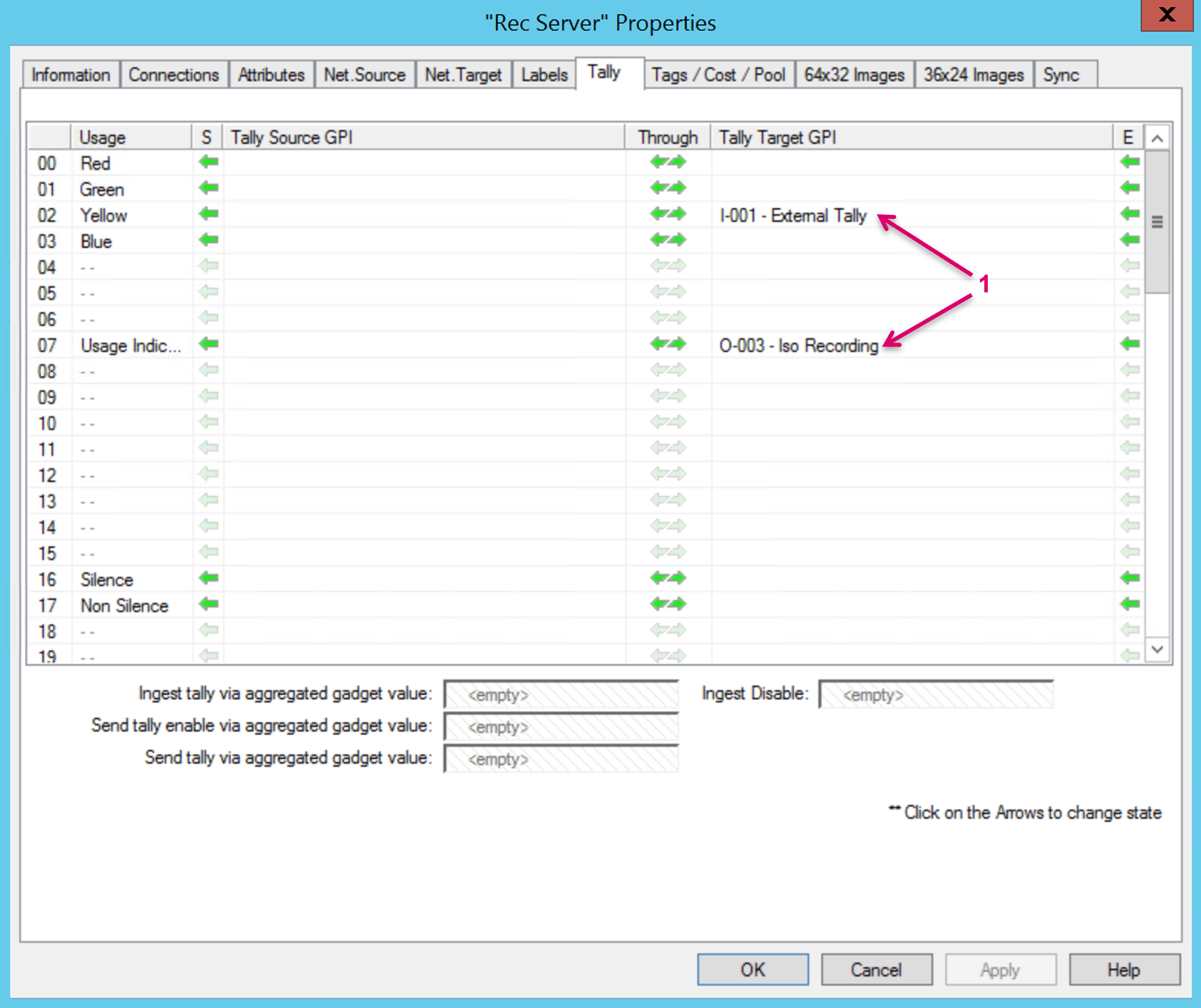
Tally Target GPI: Only applicable on Signal Path Targets. If a GPI or GPO was assigned to this Signal Path target, the respective GPIO will be displayed here (1). The cells in this column are display only, no assignments can be made in this view. If you want to assign a GPIO to a Signal Path please refer to the GPIO documentation.
Via the arrow icon in cells of the E (Enable) column, incoming System Tally can be blocked. Incoming System Tally is enabled by default once a Tally level is labeled and active. To disable Tally, just click on the arrow icon in the cell of the respective Tally-level. The icon is greyed out if disabled. Note that a direct GPIO assignment to the Signal Path will still trigger Tally.
External Tally available as Gadget Parameter can also be directly assigned to a Signal Path via Ingest tally via aggregated gadget value. Drag the parameter from the respective node in the Gadget tree and and drop it here.
- If supported by the connected device, the Tally enable status can be directly send to a Gadget parameter via Send tally enable via aggregated gadget value. Drag the parameter from the respective node in the Gadget tree and and drop it here.
- Signal Path related Tally can also be directly forwarded to a Gadget parameter via Send tally via aggregated gadget value. Drag the parameter from the respective node in the Gadget tree and and drop it here.
- Ingest Disable allows to block external tally via Gadget Parameter. To do so, drag and drop any GPIO here.
- Navigation controls. Proceed to the next step with "Next" or in Edit mode proceed with "Cancel", "Apply" or "OK".
This area provides further attributes to specify the identity and usage of Signal Paths. Tag words may be used to classify and identify a Signal Path. This allows for instance, to enable or disable specific crosspoint routes or identify the possible need for a converter/processing device, which then consecutive may be followed by the automatic insertion of a "Pool device". Before Tags or Pools can be assigned, Tag Groups, Tags and Pools have to be created via the System Properties view.
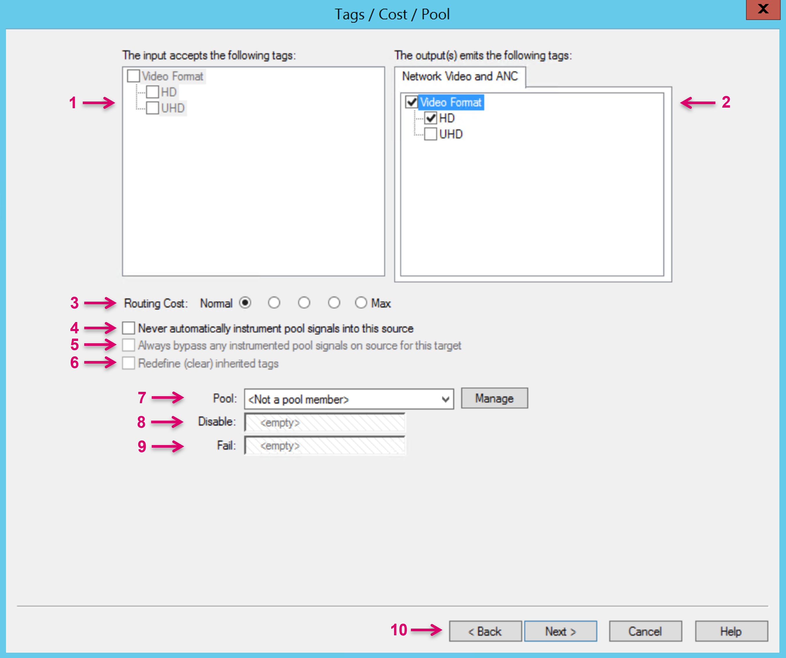
- The input accepts the following tags: Applicable on Signal Path Targets. Available Tag Groups and Tags, as created via the Matrix Properties view, are listed here and can be selected accordingly.
- The output(s) emits the following tags: Applicable on Signal Path Sources. Available Tag Groups and Tags, as created via the Matrix Properties view, are listed here and can be selected accordingly.
- Routing Cost: Routing Cost´s allows to prioritize the automated use of processing resources based on their "cost". This option may be used for instance, to prevent the utilization of "expensive" (Max) signal processing resources before all "cheaper" (Normal) signal processing resources have been utilized.
- Never automatically instrument pool signals into this source is applicable on Signal Path Sources. No Pool device will be inserted automatically even if available and applicable based on Source and Target tags.
- Always bypass any instrumented pool signals on source for this target is applicable on Signal Path Targets. This attribute will force this Signal Path Target to only accept the direct Signal Path Source. Any pool signal that may stick with the selected Signal Path Source will be bypassed.
- Redefine (clear) inherited tags is applicable on Signal Paths configured with Source and Target leg.
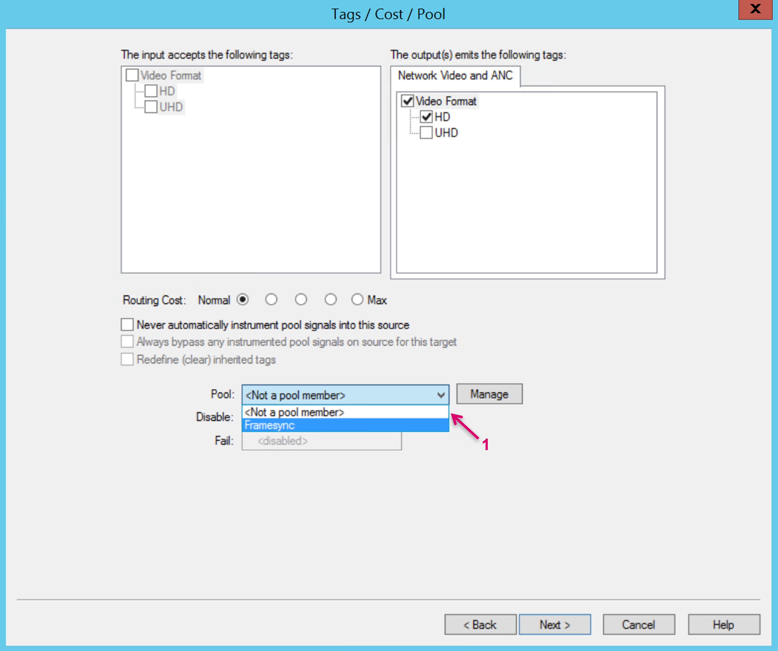
Pool: Define this Signal Path as a Pool device by assigning any available Pool that was created via the Matrix Properties view. Pools can be managed via the Manage dialogue.
To assign or un-assign an already created Pool select the respective option from the drop-down menu (1).
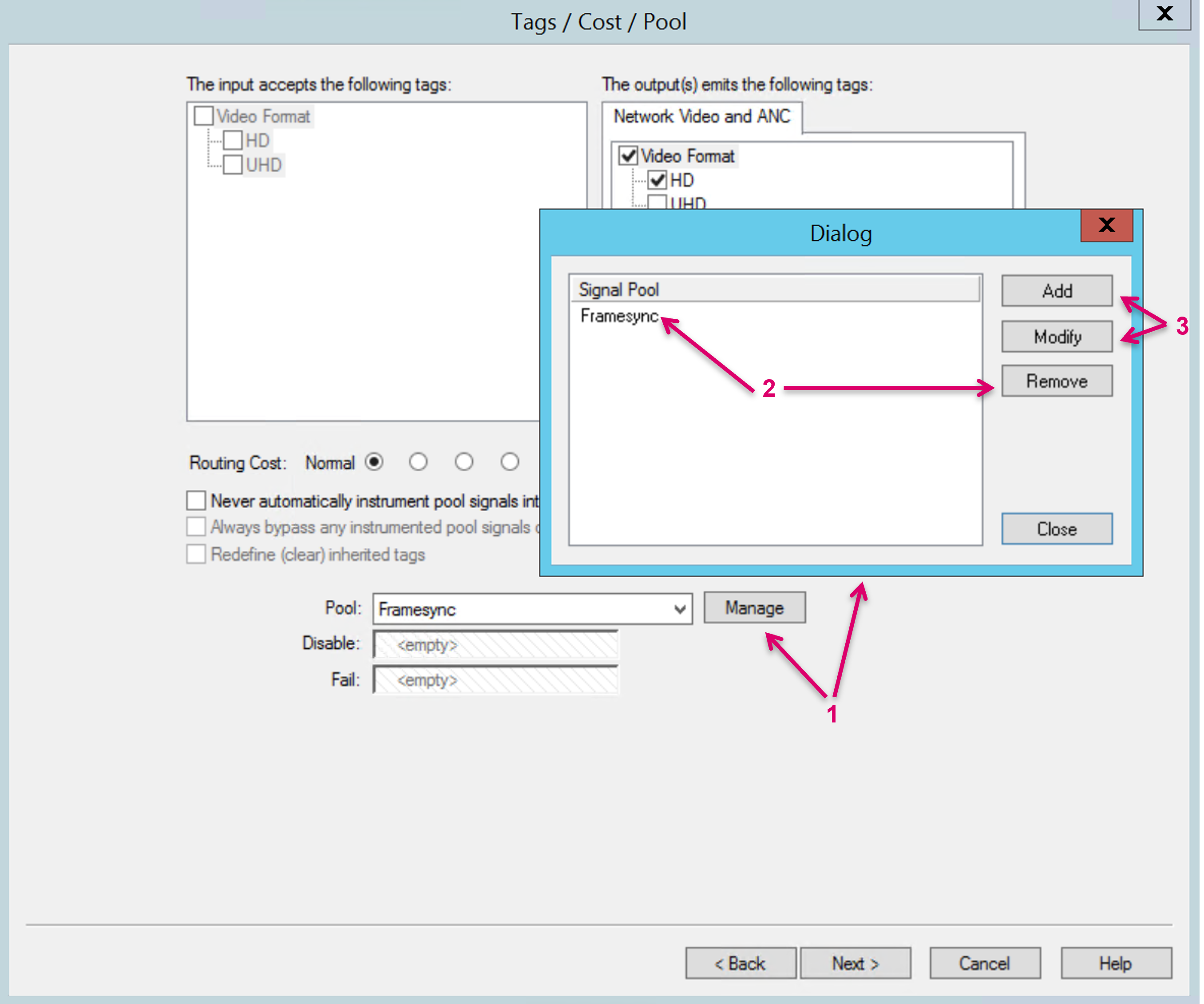
To modify, remove or create a Pool select "Manage" (1) which opens a dialog box. To remove a Pool, select the respective Pool and choose Remove (2). To Add or Modify a Pool, select the respective Option (3) which opens another dialog box.
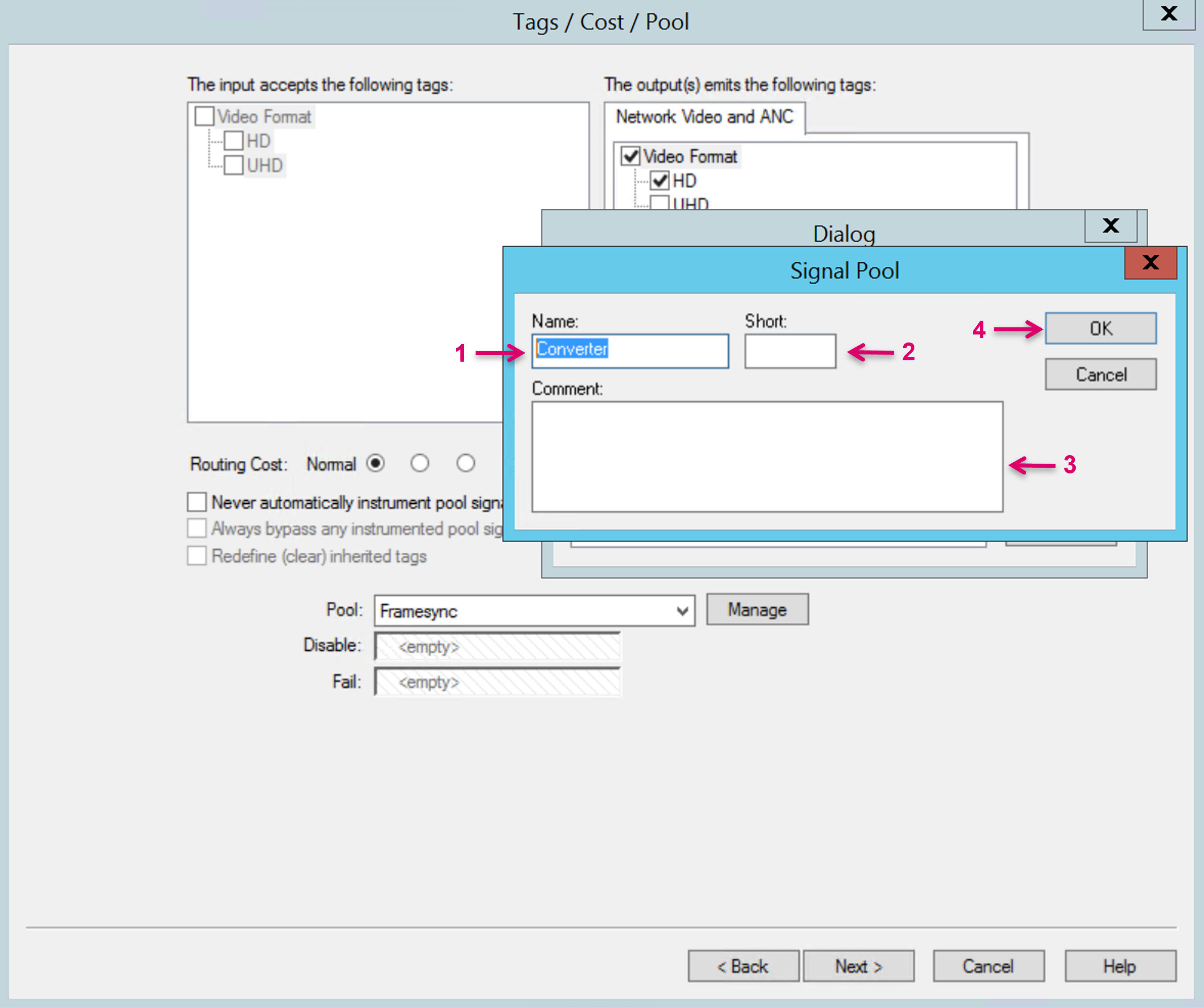
In the opening dialog set or modify the Pool "Name" (1). Assign an optional "Short" name (2). Add optional information in the "Comment" field (3). Continue with "OK" (4).
- Disable: Drag and drop any GPIO. If this trigger gets true this Signal Path will be temporarily removed from the Pool. It will not be considered any longer as available resource for future routes. Any current routing is not affected.
- Fail: Drag and drop any GPIO. If this trigger gets true this Signal Path will be removed from the Pool and immediately replaced with a next available pool device.
- Navigation controls.
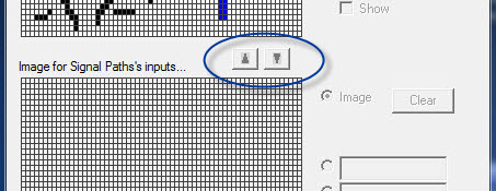
In the next window 64x32 Images, a bitmap can be created for the signal. It is displayed on panels.

Two lines of text can be entered and moved to the desired position. Alternatively, select Image and draw an image. The blue element hereby represents the active one. If loop-through devices are used, an image can be created for both input and output. All other signals are usually represented with one image only.
Using the two arrows located between the two areas, an image can be transferred from one area into the other:
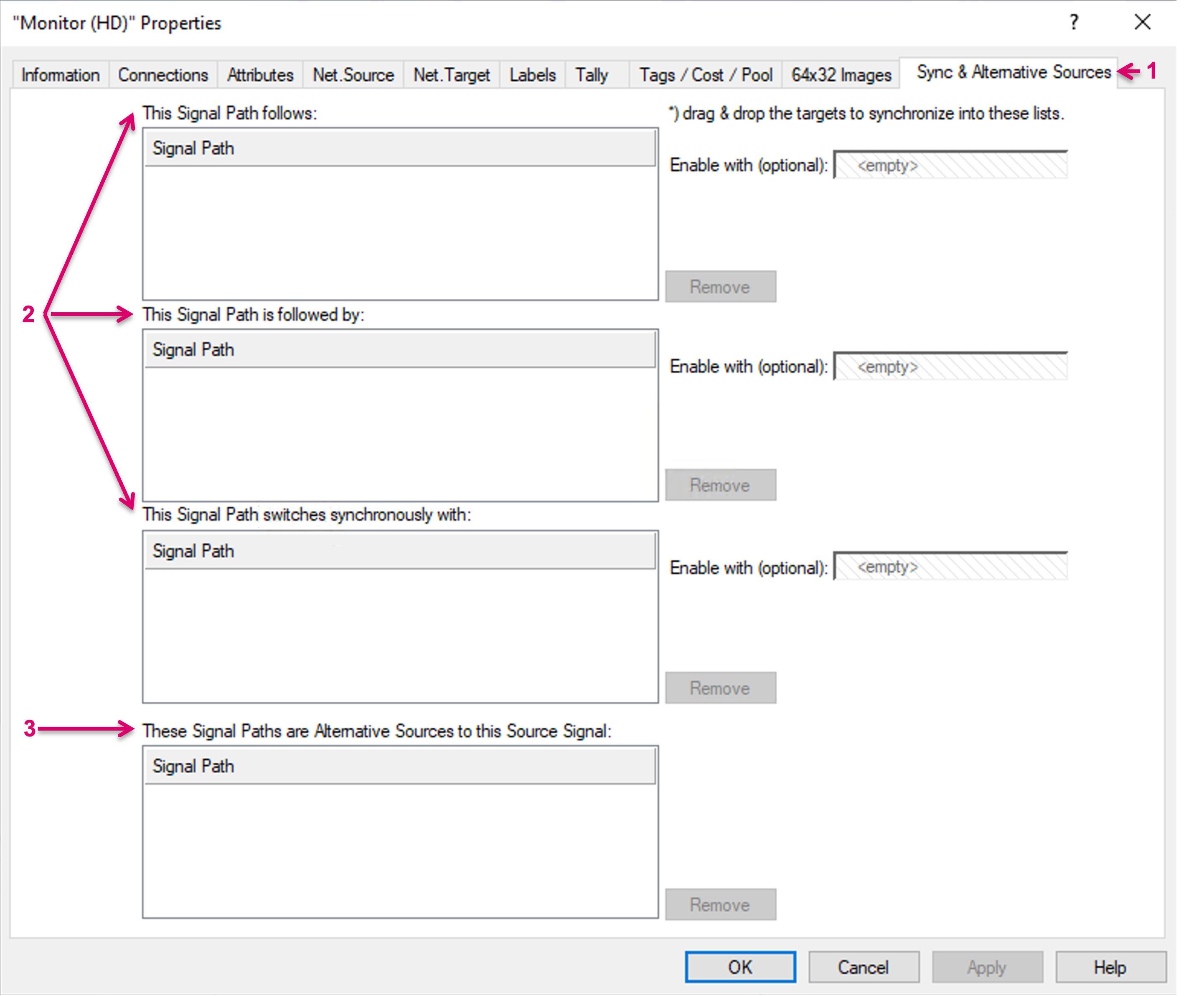
The section Sync & Alternative Sources (1) allows to define a synchronised switching behaviour for selected targets as well as to define alternative Sources for a currently configured Signal Path source.
Target Synchronisation
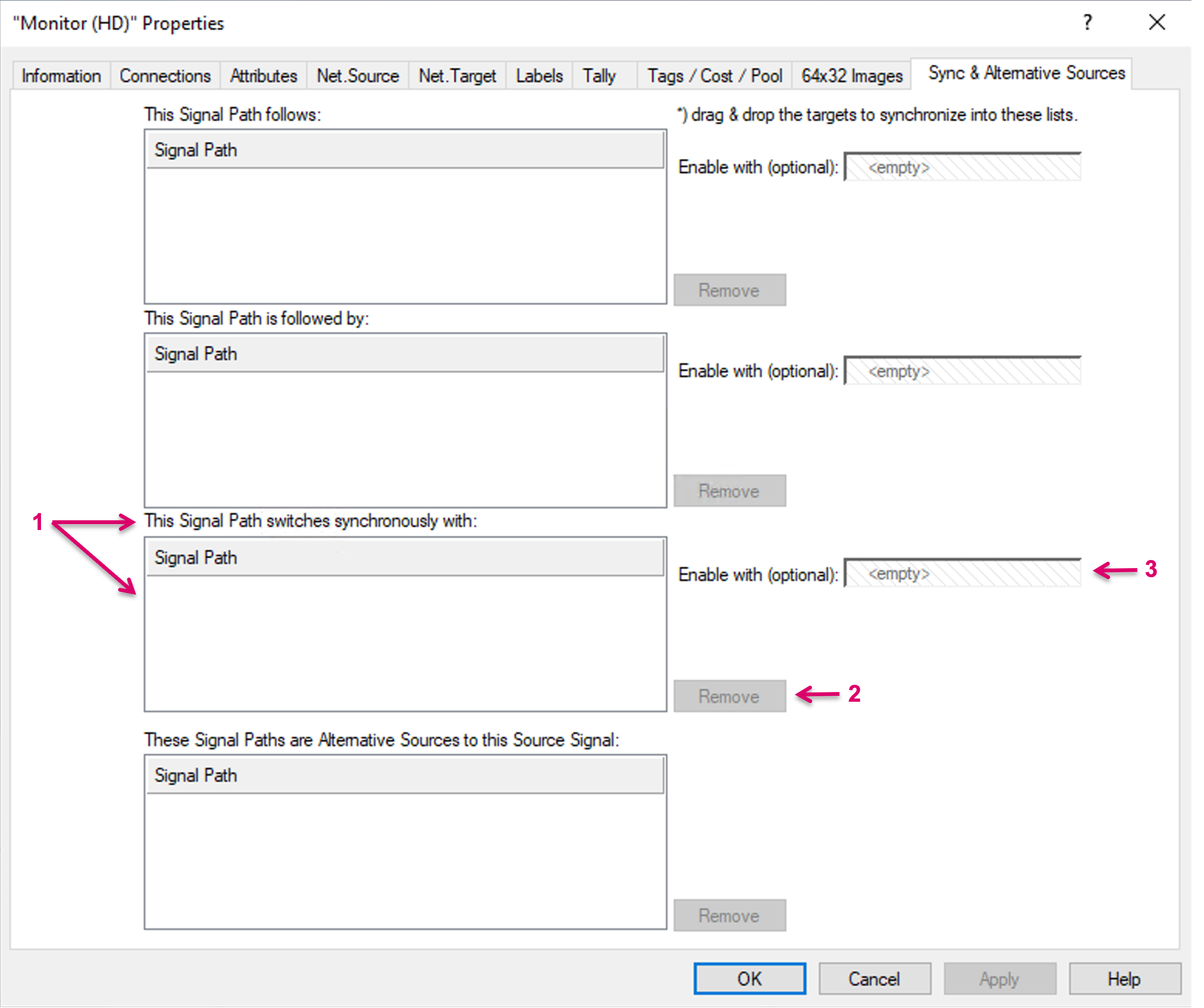
A synced switching behavior can be configured for Signal Path targets only, e.g., a Monitor destination (1).
By drag and dropping one or multiple Signal Path targets into the drop zone of This Signal Path follows (2), the momentarily edited target will follow the routing of any of the dropped targets. On the dropped target(s) the assignment will show accordingly under "This Signal Path is followed by". So, the dropped target will act as the leading target and every time it is switched to a different source, the current target will switch to that same source. If multiple targets are defined here and routed to different sources, the last route will win. While the momentarily edited target will follow the routing action to the other targets, it can still be routed separately and keep that routing until a source change to any of the other targets will trigger the sync action again. The sync configured here is not bidirectional, means the dropped targets will not follow routing action to the momentarily edited target.
Already dropped Signal Path targets can be removed by selecting them, followed by clicking "Remove" (3). Multi-selection is possible.
For advanced workflows it is possible to Enable the target sync via GPI. To configure this, drop a GPI in the respective field (4). In this case, the target sync will only be active if the attached GPI is true.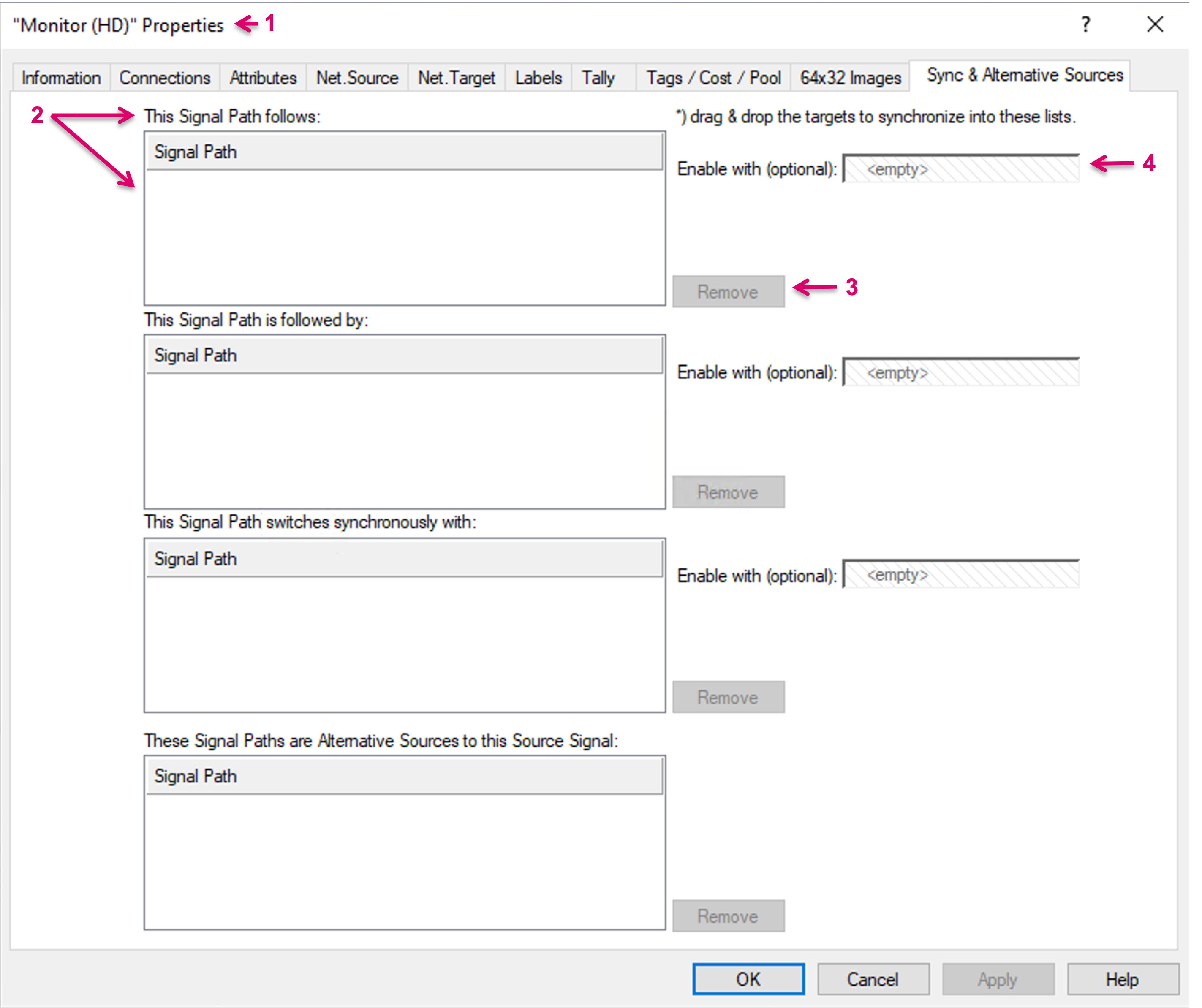
By drag and dropping one or multiple Signal Path targets into the drop zone of This Signal Path is followed by (1), the dropped target(s) will follow the routing of the momentarily edited target. On the dropped target(s) the assignment will show accordingly under "This Signal Path follows". So, the momentarily edited Signal Path target will act as the leading target and every time it is switched to a different source, the dropped target(s) will follow and switch to the same source. The sync configured here is not bidirectional, means the momentarily edited target will not follow routes to any of the dropped targets.
Already dropped Signal Path targets can be removed by selecting them, followed by clicking "Remove" (2). Multi-selection is possible.
For advanced workflows it is possible to Enable the target sync via GPI. To configure this, drop a GPI in the respective field (3). In this case, the target sync will only be active if the attached GPI is true.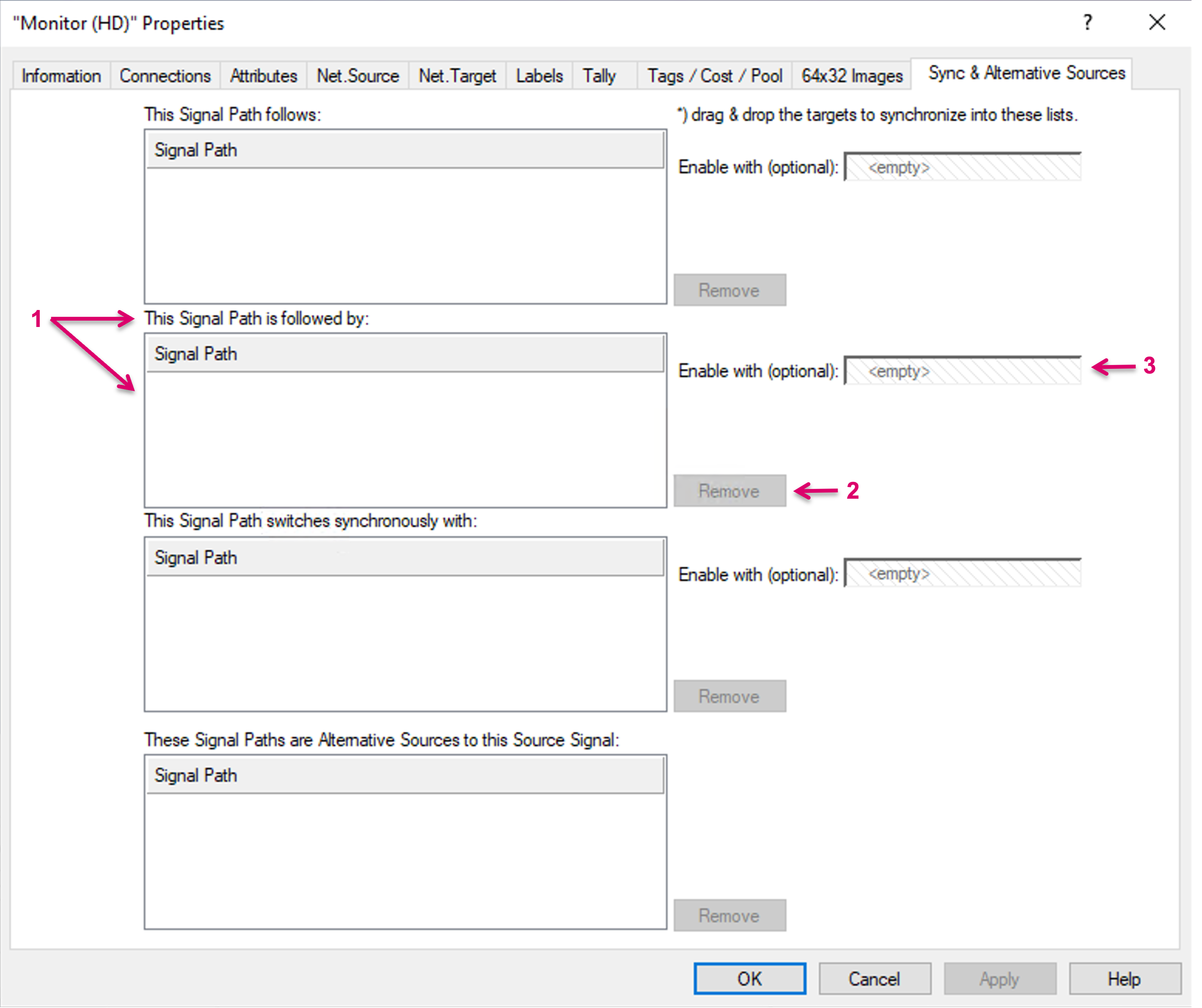
By drag and dropping one or multiple Signal Path targets into the drop zone of This Signal Path switches synchronously with (1), the dropped target(s) and the momentarily edited target will always switch synchronously. On the dropped target(s) the assignment will show accordingly in the same area. So, no matter which of the respective targets is switched, all assigned targets will follow the same source selection. Means the sync configured here is bidirectional and the last route will win.
Already dropped Signal Path targets can be removed by selecting them, followed by clicking "Remove" (2). Multi-selection is possible.
For advanced workflows it is possible to Enable the target sync via GPI. To configure this, drop a GPI in the respective field (3). In this case, the target sync will only be active if the attached GPI is true.
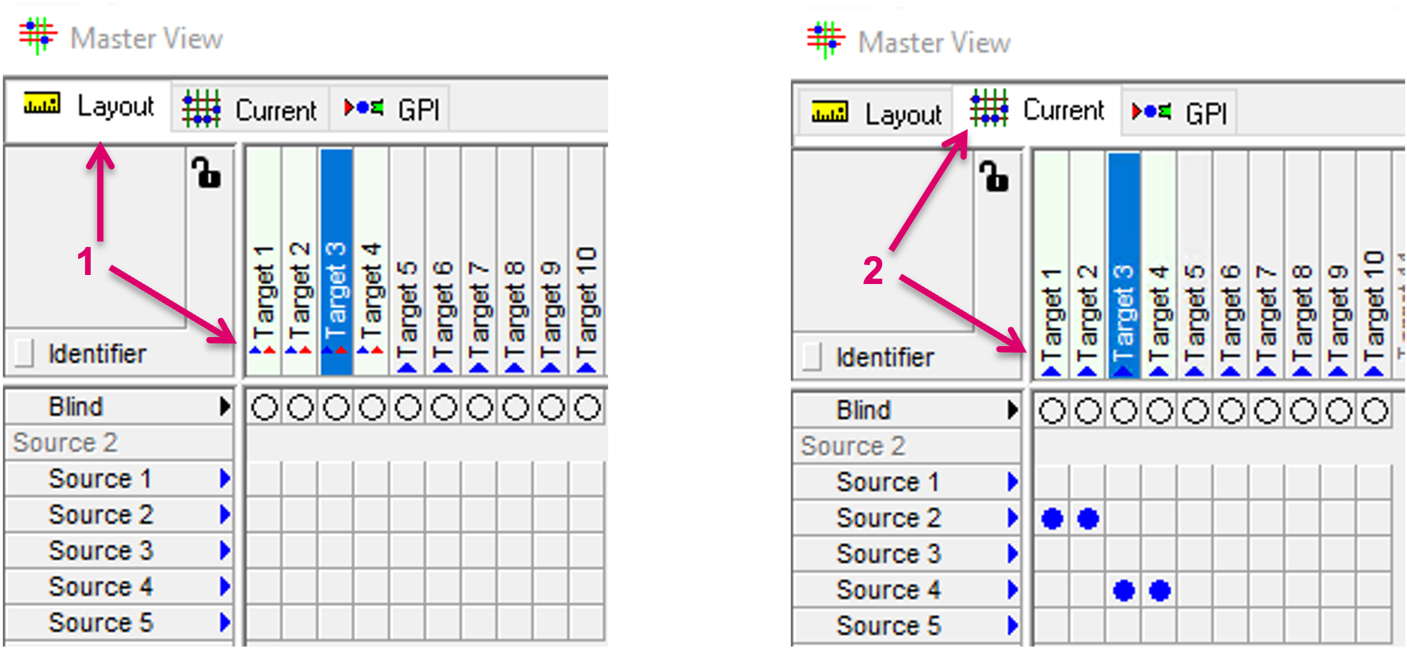
In the matrix view, any configured Sync is displayed in light green background on the respective target Signal Paths. Slightly different depending on if "Layout" (1) or "Current" (2) tab is selected.
Alternative Sources
The Alternative Sources feature allows to define and assign multiple Sources to one Signal Path source. This feature can be used with physical as well as virtual Signal Path sources and allows workflows, where one single Source Signal Path trigger can then be used to connect different physical sources and targets based on their specific Tag information or layer assignment.
To configure the assignment, open the Properties of a Signal Path source that shall act as Source trigger in the workflow. In the following example a Camera feed is delivered from the base unit in different formats, like HD, SD and UHD. The idea is that the operator should not need to worry about which specific Source of the Camera he must select for a specific target based on the individual end device. The intention is to allow to just pick a Source "Camera", while the system can decide, based o the Alternative Source configuration, which physical Signal is the most appropriate.
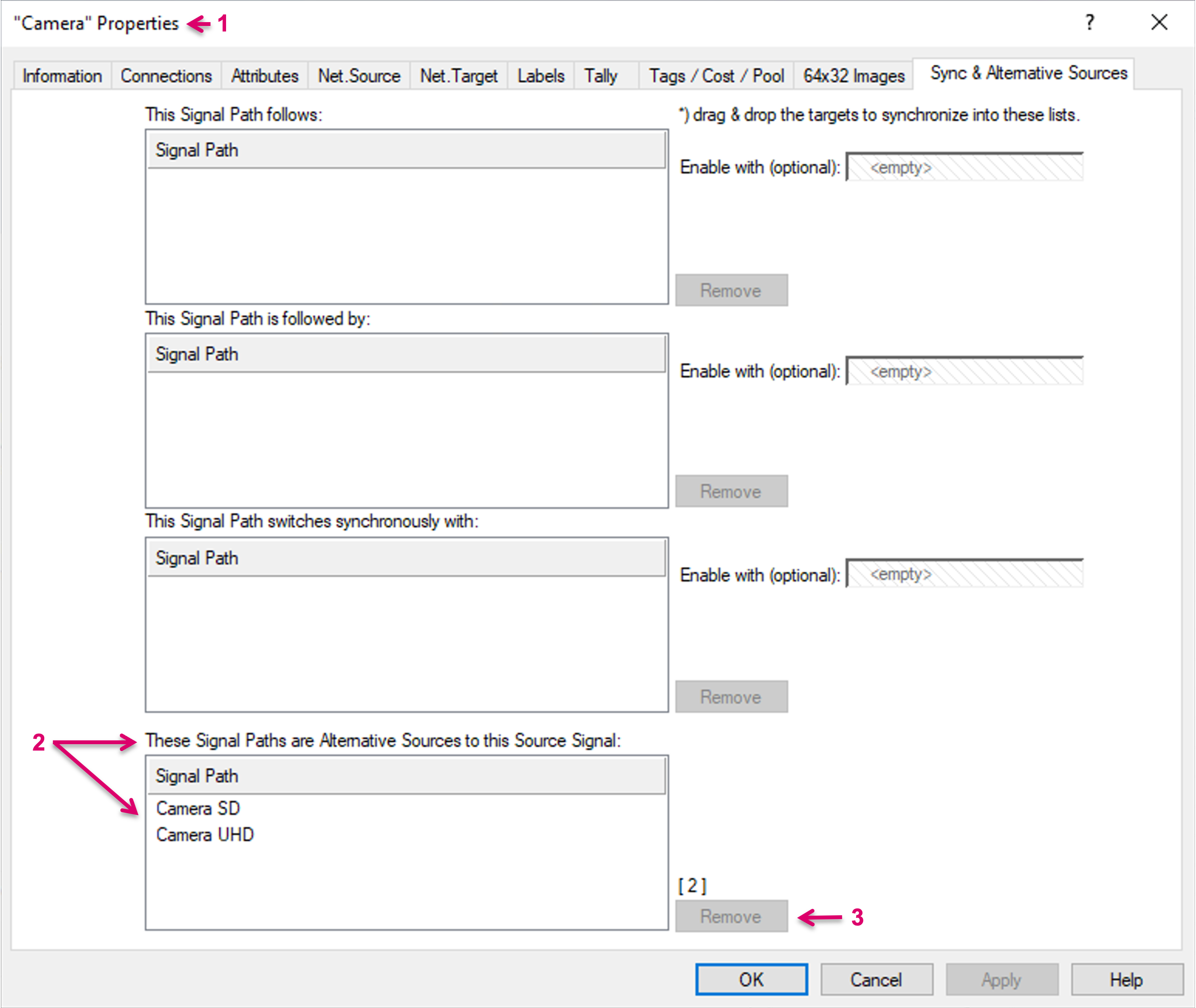
In the Properties view of the Signal Source "Camera" (1), one or multiple Signal Path sources can be dragged and dropped in the area These Signal Paths are Alternative Sources to this Source Signal. In the example, the edited Signal Path "Camera" is effectively the representation of the physical Camera output in HD format. The dropped Signal Path sources are the physical Camera outputs in SD and UHD format (2). The Alternative Source assignment is not bidirectional, means selecting and routing any of the dropped Signal Path Sources in the workflow directly, the Alternative Source logic will not apply.
Already dropped Signal Path sources can be removed by selecting them, followed by clicking "Remove" (3). Multi-selection is possible.
Alternative Sources may be located on different layers or being tagged with a different format Tag.
While the assigned Sources may be located on separate layers, please note that the system will always choose "the shortest" possible route and in this respect also prioritise a locally available Source before a potential alternative on another layer with available tie-lines in between.
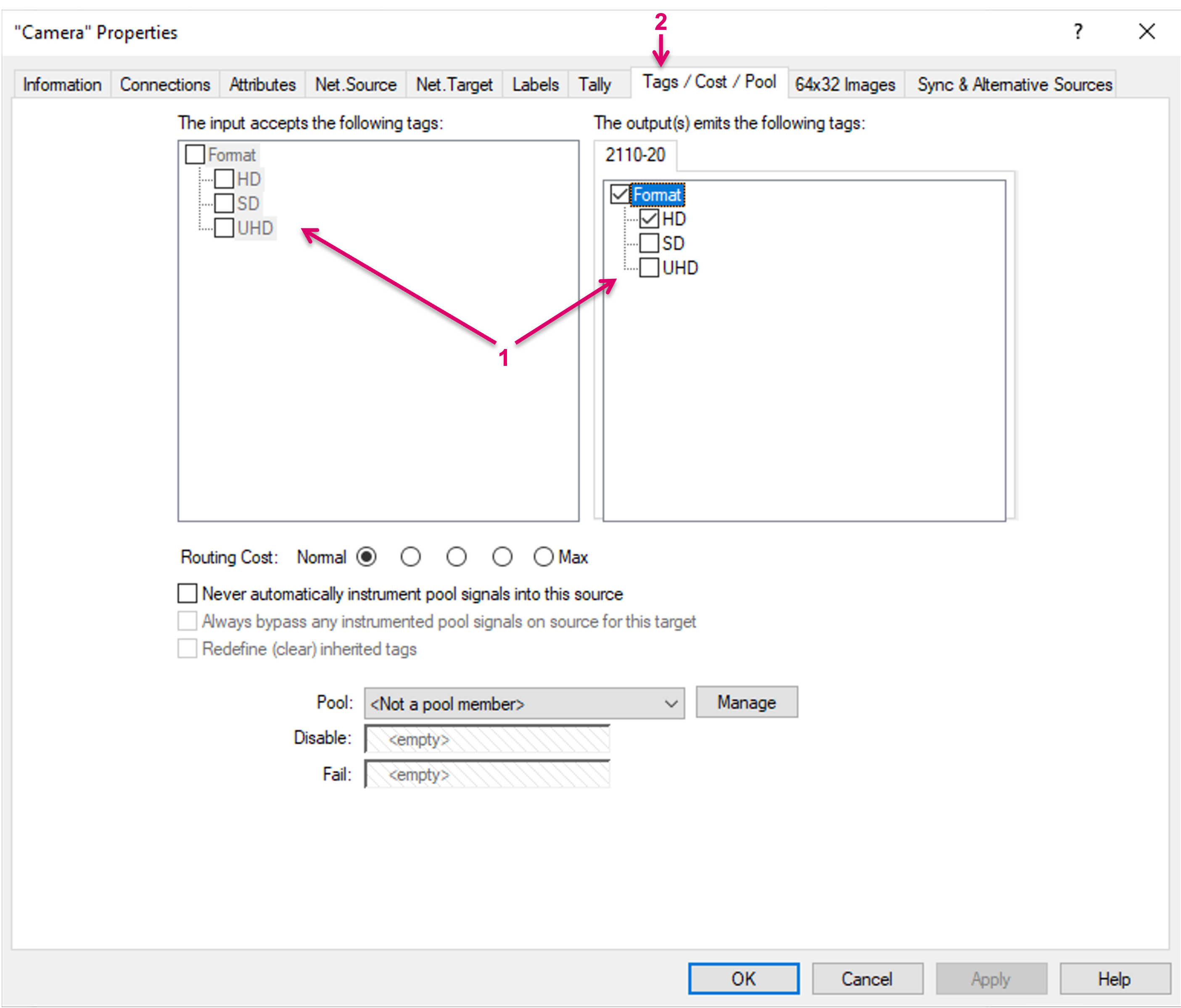
In general, different output formats or required input formats (1) may be specified via Tags (2). Based on the Tag settings, setting a crosspoint between Source and Target may be possible or not. In context of Alternative Sources, Tags allow the system to find the most appropriate Source to target route. Before Tags can be selected and assigned, Tag Groups and Tags must be created via the System Properties view.
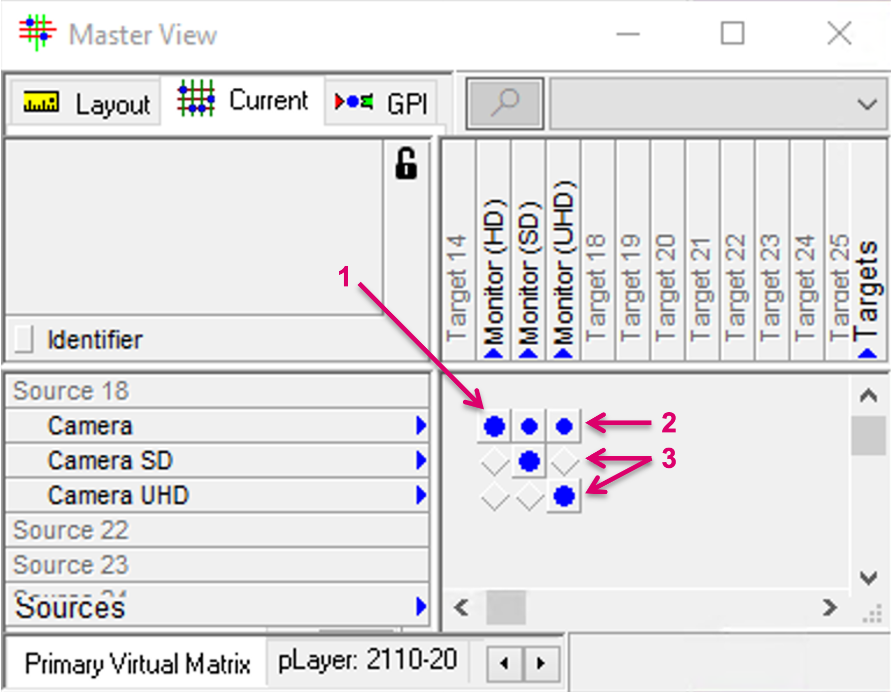
In the matrix view, direct crosspoints are displayed via the common blue dot, while crosspoints made by an Alternative Source trigger are indicated with a slightly smaller blue dot (2). The resulting direct crosspoints are displayed as well (3). In the example, Different Monitor targets require specific signal formats of the same Source. The selected Source for all Monitor targets was "Camera".
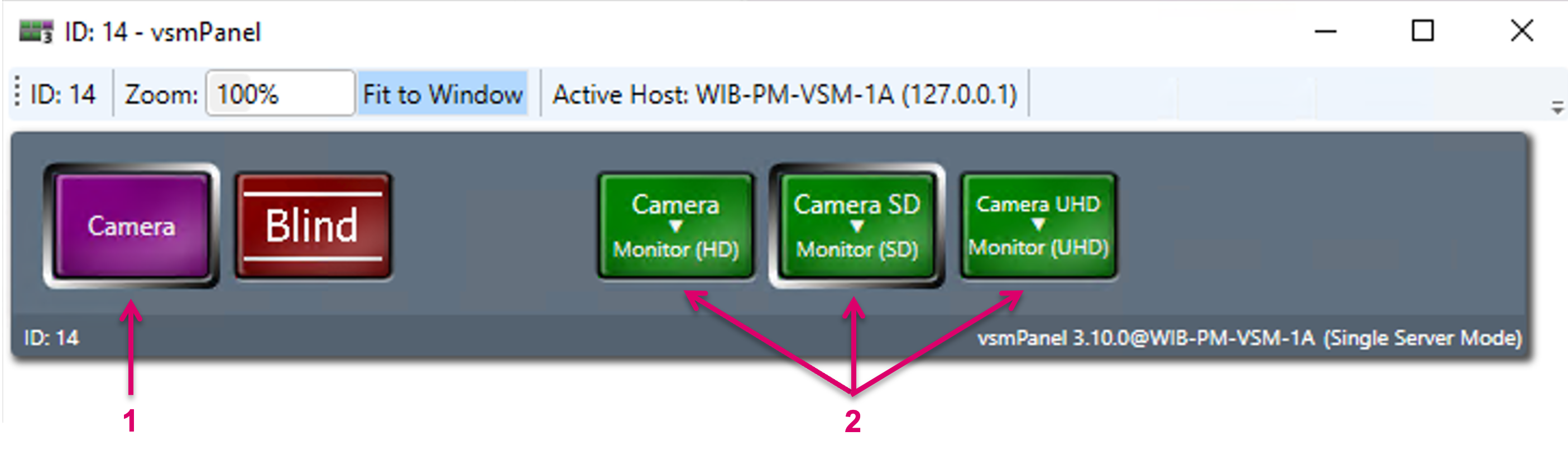
On the operator panel, the same Source (1) can be selected for all Monitor targets (2). In the background the system checks for the respective attributes and feasibility and makes the appropriate choice and executes the route. In case any of the routed alternative sources was assigned to a button on the panel as well, the respective selection border on this button will show as well, but it will be slightly dimmed.
Specific changes to the Signal Path configuration may require a re-load of the configuration. If changes do not show the expected result, please save the configuration after any Signal Path change and if applicable close and re-load the respective configuration again.