vsmStudio - Pseudo Devices

Introduction
The Pseudo Device feature in vsmStudio allows to link various Signal paths to one, so called, Trigger Signal. This logical grouping of Signal paths in Pseudo Devices is one essential feature that enables extended functionalities for the general Signal and Resource handling.
For instance:
- Signal paths, even from different physical layers, can be handled as one logical device.
- It allows to connect multiple sources to multiple targets based on one single crosspoint trigger. This function is frequently used e.g., to route Multi-Audio Mono Channels on one button push or to allow Audio-follow-Video.
- In combination with Dynamic Attachment Scripts, it introduces an additional layer to track down Signal attributes, e.g., assigned Meta Gadgets.
- It allows to make use of the Shuffle Button in Panel layouts. Pseudo Device attachments/ columns form the basis for the respective Shuffle The Shuffle Patterns are also configured within the Pseudo Device section.
- It allows to make use of the PTT (PushToTalk) Button in Panel layouts. The required Signal and Parameter dependencies are configured as specific Pseudo Device rules, so called Ports.
- Pseudo Devices are also the basis for the Media Essence Filter functionality, required in combination with network devices that only support grouped 2110 SDP information.
Signal Paths of type Tie-Line are currently not supported with Pseudo Device rules.
Overview of the Pseudo Devices View
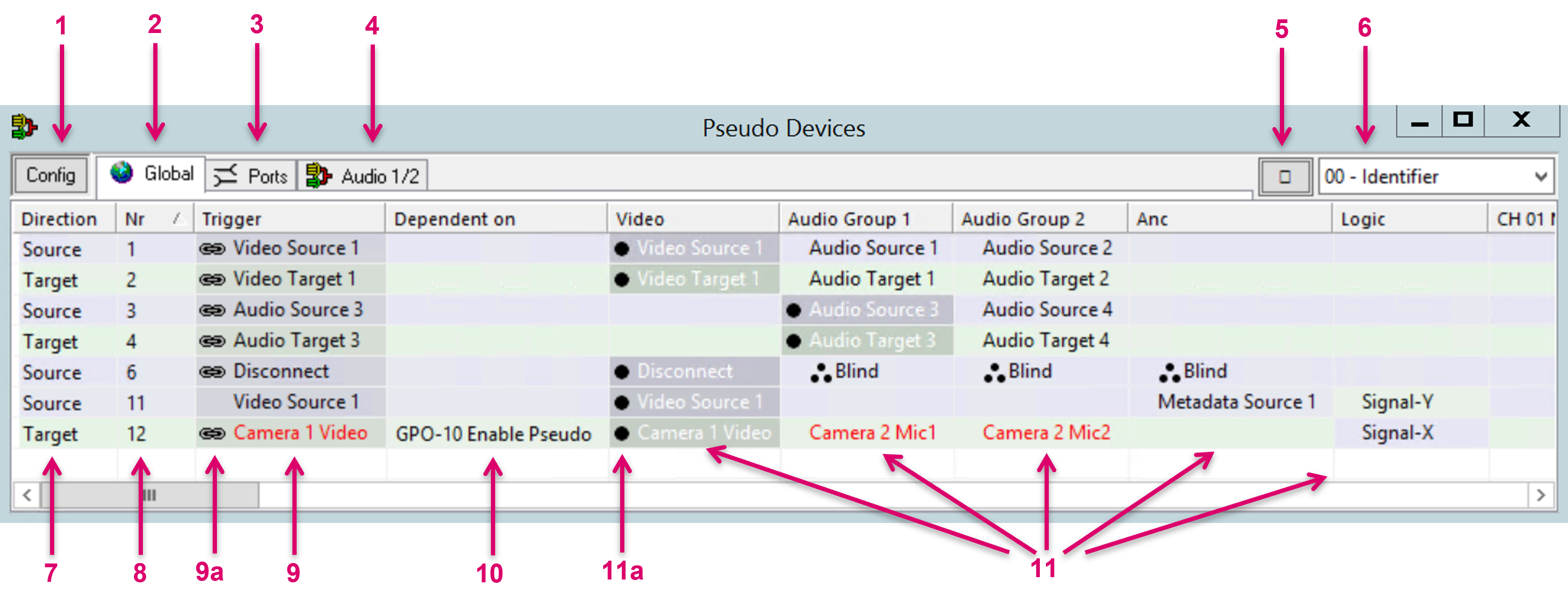
1 - Tab “Config”: Navigate to this tab to Add, Modify or Remove customizable columns and Groups for the Pseudo Devices view and predefine Shuffle logic.
2 - Tab “Global”: The general Pseudo Devices view to monitor and administrate Pseudo Devices.
3 - Tab “Ports”: Navigate to this tab to configure PTT related Pseudo Device rules only.
4 - Tab “Group/ tbd”: Pseudo Device Group tabs are optional and can be configured via the Config tab.
5 - Search: Clicking this icon opens and Search and Find window to browse the list by keywords.
6 - Label selector: Select the displayed label level for all Signals in the Pseudo Devices view.
7 - Static Column “Direction”: Shows if the Trigger Signal of this Pseudo Device is a Source or a Target.
This is also indicated by the background-color of the respective row,
8 - Static Column “Nr”: May be used to sort the list entries. No further functional relevance.
9 - Static Column “Trigger”: Cells are filled automatically with the first dropped Signal on any cell of the respective row. Shows the Signal that acts as trigger for the attached set of Signals. To execute a Pseudo Device rule in the routing process, it is essential that the Trigger is defined accordingly for both, Source and Target, in addition to the general compatibility of Source and Target Signalpath.
9a - Symbol “Bind”: This chain icon next to a Signal indicates that this Signal, defined as a Pseudo Device, will be considered by the System for internal calculations, e.g., in conjunction with Dynamic Attachment Scripts. The same Signal may exist multiple times in the list but only one appearance and its attached rule can be defined as “bound”, which is also the default setting when dropping a Signal, the first time into the list.
10 - Static Column “Dependent on”: GPIO or Crosspoints may be dropped in this column cells to only enable the respective Pseudo Device rule if state is “true”.
11 - Customizable Columns: Signal paths may be dropped in cells of these columns. The first Signal dropped in a row is automatically defined as the Pseudo Device Trigger. This is also indicated by a black dot next to the Signal (11a). Virtual Signals are displayed as red text.
Configuration of the Pseudo Devices View
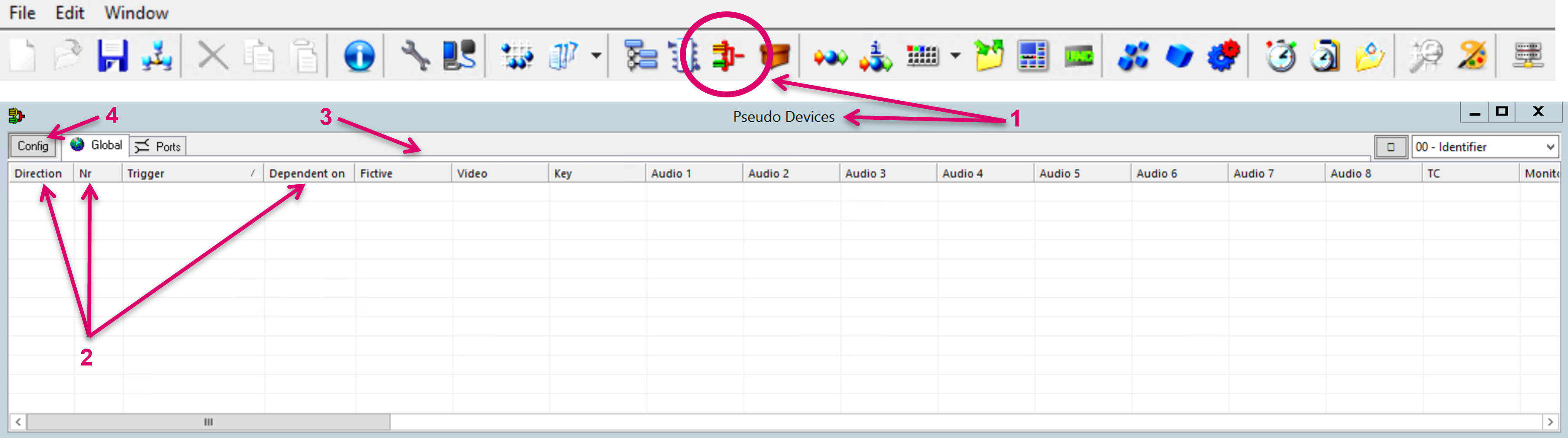
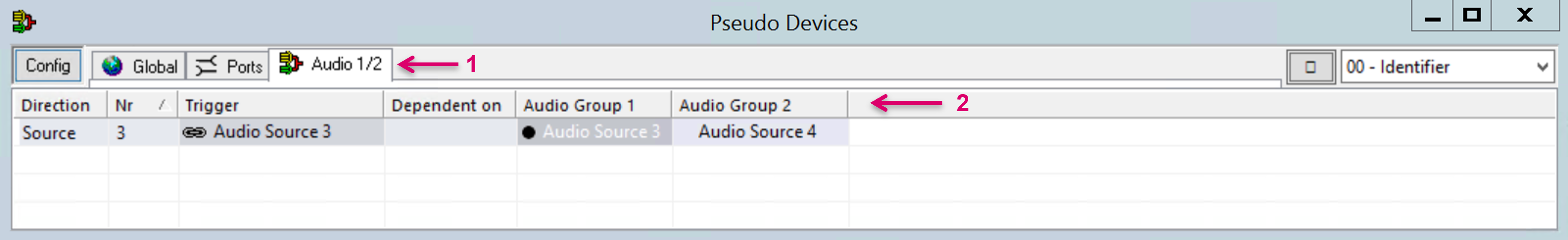
Open the Pseudo Devices view by click on the respective icon on the vsmStudio top toolbar (1). The opening table provides some pre-defined, static columns [Direction, Nr, Trigger and Dependent on (2)], all others (3) may be customized. Select the Config tab (4) to access the Manage Pseudo Device view.
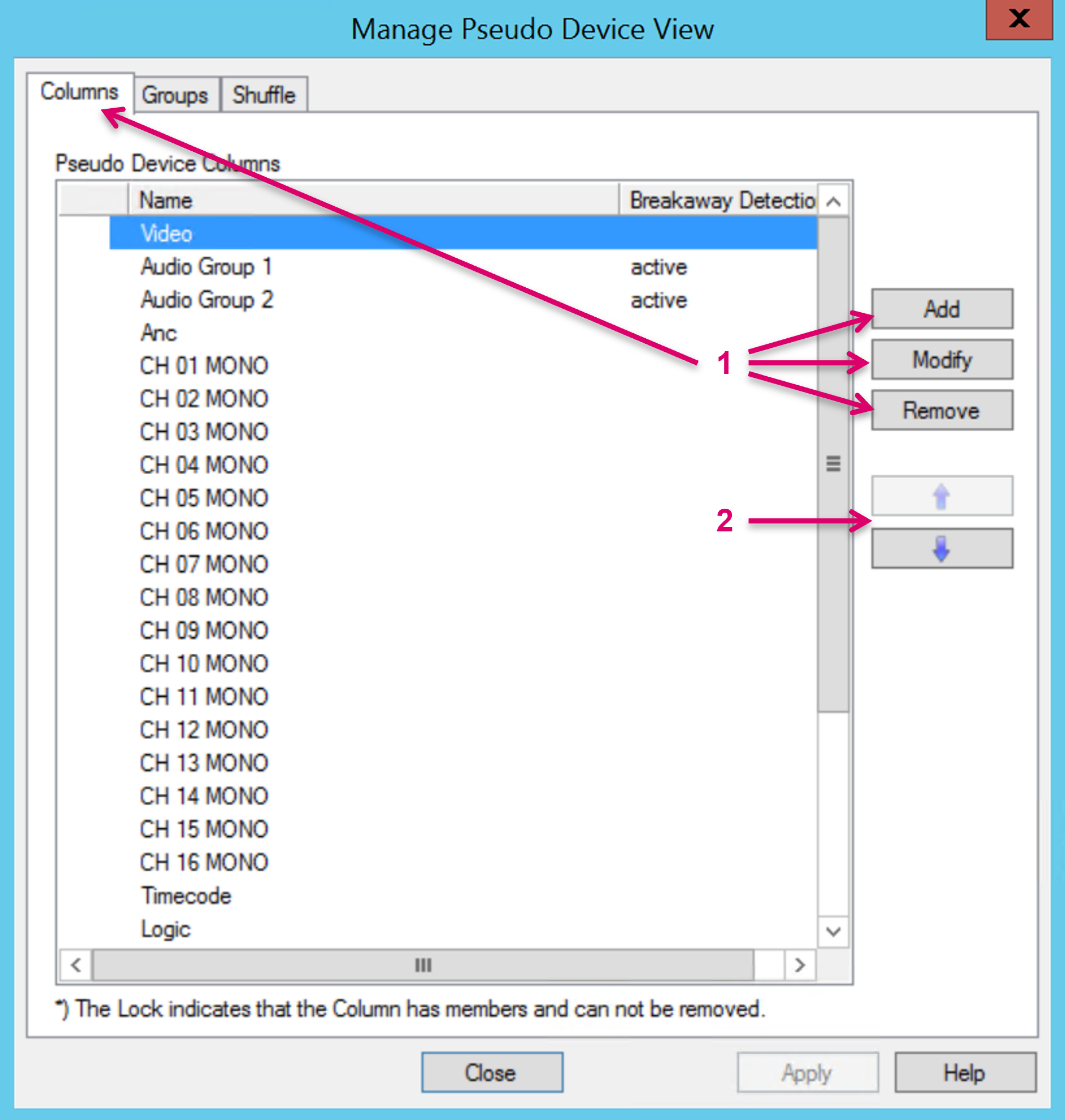
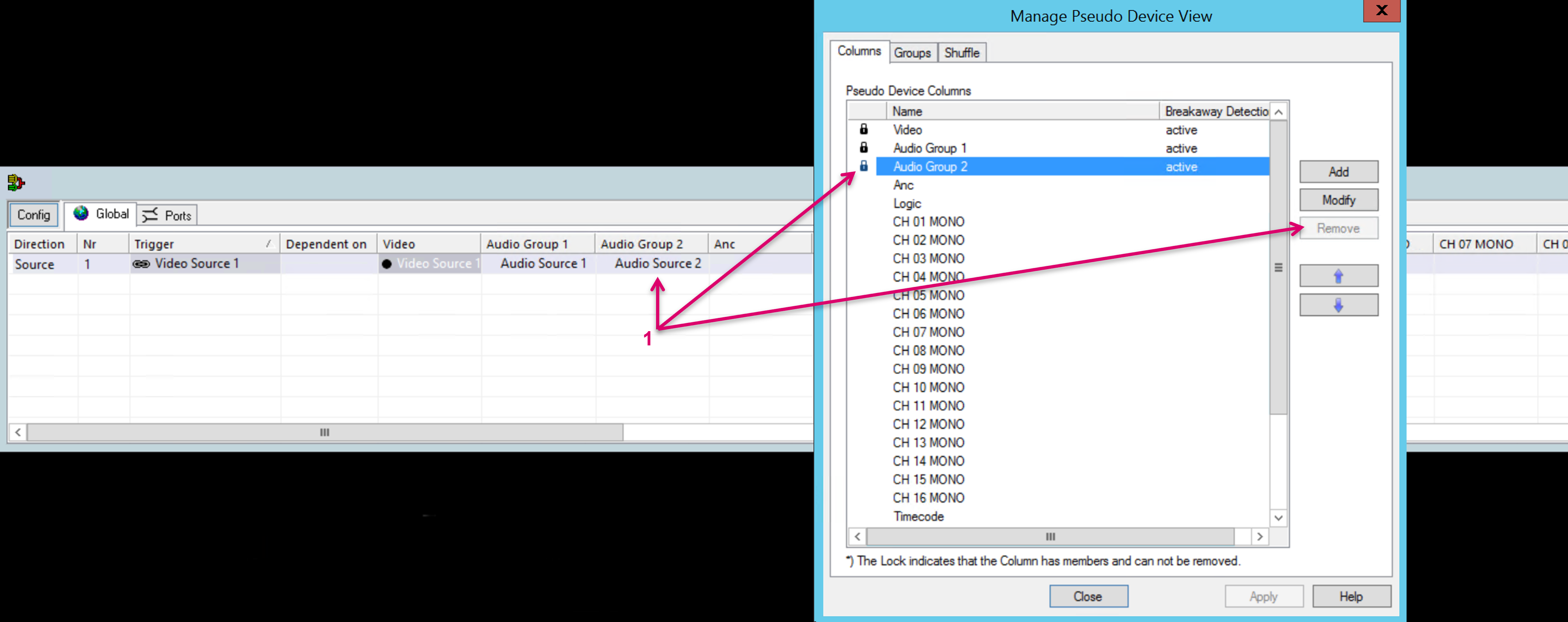
Navigate to the Columns tab of the Manage Pseudo Device view, to Add, Modify, or Remove Columns (1). The displayed order of Columns can be changed as well by selecting a Pseudo Device column by Name and clicking the up and down arrow keys (2).
When adding or modifying a Pseudo Device Column, a Name can be set (1), and you may Enable Breakaway detection (2).

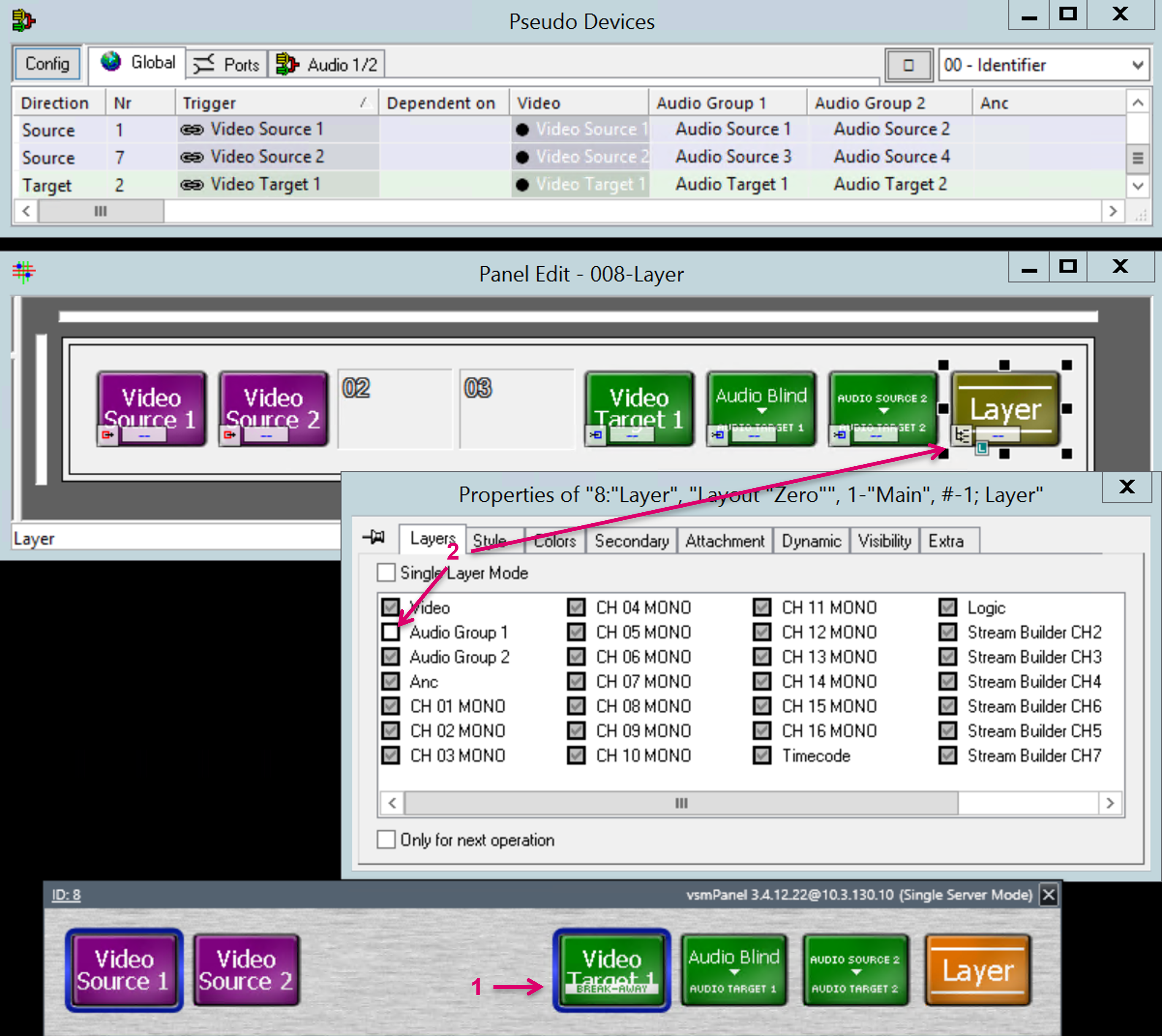
Breakaway detection allows to status on panel buttons, if the respective Column was not included in the execution process of a Pseudo Device rule (1), e.g., if specific Layers were excluded from a route via the function button “Layer” (2).
Remove Columns is available unless any Signal is assigned. Once a Signal is assigned, a Lock Icon indicates that the respective Column is protected (1).
Create Pseudo Devices
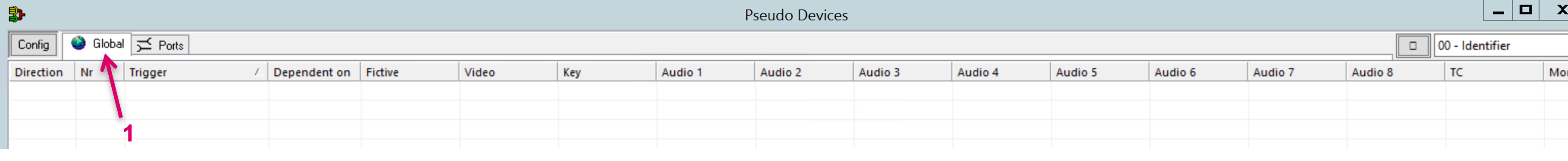
Navigate to the Global tab of the Pseudo Devices view (1).
To create Pseudo Devices, Signals have to be dragged from the Signal List (1) or any Matrix view (2) and dropped in the appropriate column and cell.
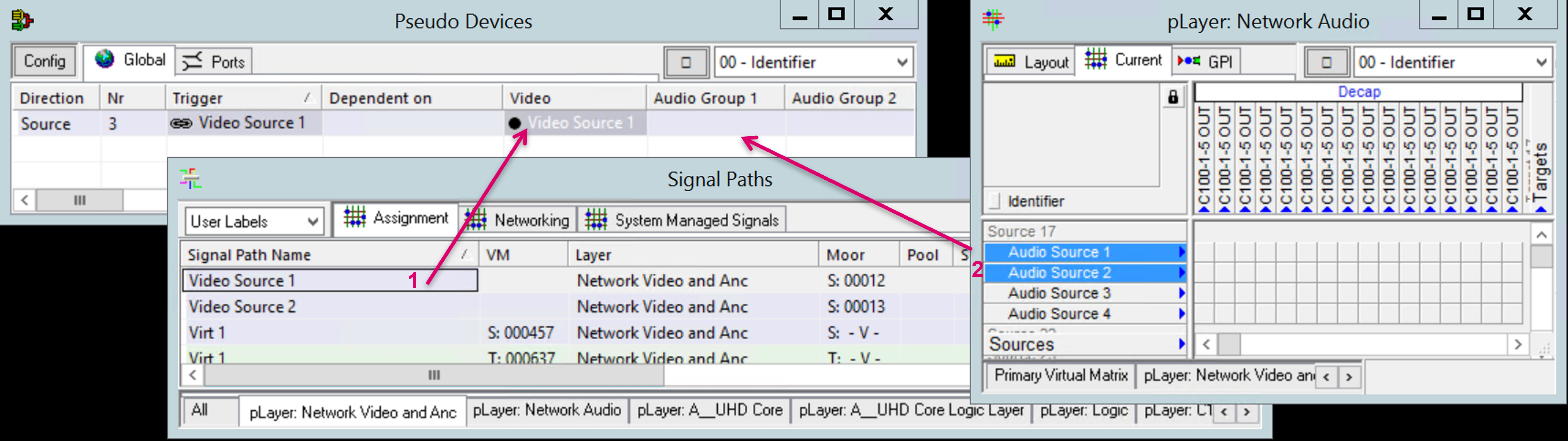
Multiple signals can be selected at the same time and dropped individually by pressing the Alt key while holding the left mouse button.
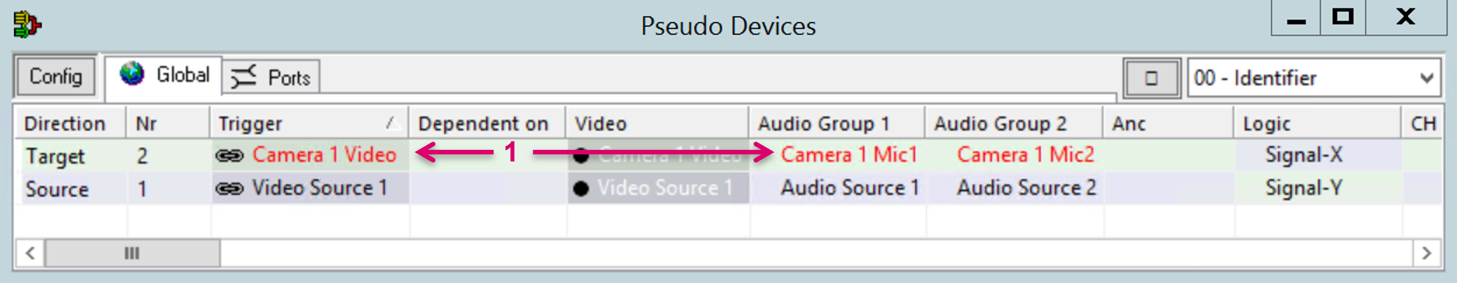
The first signal dropped into an empty row of the Pseudo Devices list, represents the Pseudo Device rule and in combination with the specific Column it was dropped into, it defines the Trigger for when this rule is used. The Signal must be dropped on a cell in any of the configurable columns (1), not in the Trigger column. The respective cell in the Trigger column will be filled automatically (2) and in addition a black dot next to the Signal will indicate the Trigger Signal (3). By dropping the Signals onto any header cell, the system will also assume a desired "add pseudo device" action and will assign the trigger accordingly.

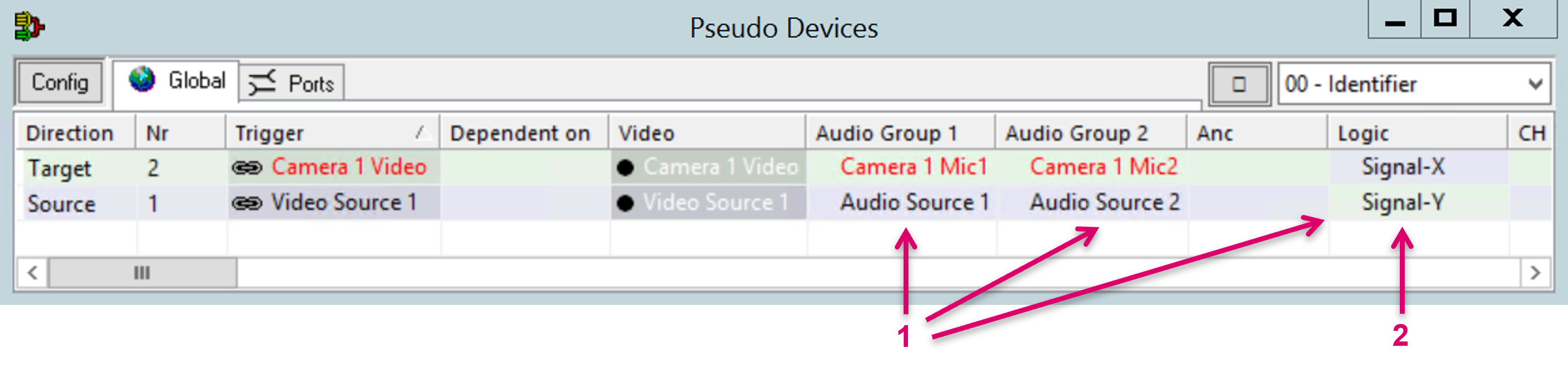
A Pseudo Device rule will only become operative and be used in routing processes, if the Trigger for both, the Source, and the Target Signal, is defined in the same column (1).

Once a Trigger Signal is dropped, further Signals can be assigned by drag & and drop operation on the respective cells of the same row (1). Assigned Signals will follow the Trigger, means when a Crosspoint is made from a Trigger Source to Trigger Target, all assigned Signals will follow that action, based and depending on the respective Signal assignment. While the Signal assignments to a Source Trigger Signal may usually be of same Direction type, it is yet possible to assign a Target Signal to Source Trigger as well as Source Signal to Target Trigger (2). This allows for a bi-directional routing action.
Virtual Signals dropped into the list are displayed in red text color (1).
To simplify the Pseudo Device creation and Signal assignment process, especially for bulk operation, it is also possible to pre-define specific drop-target columns including the order.
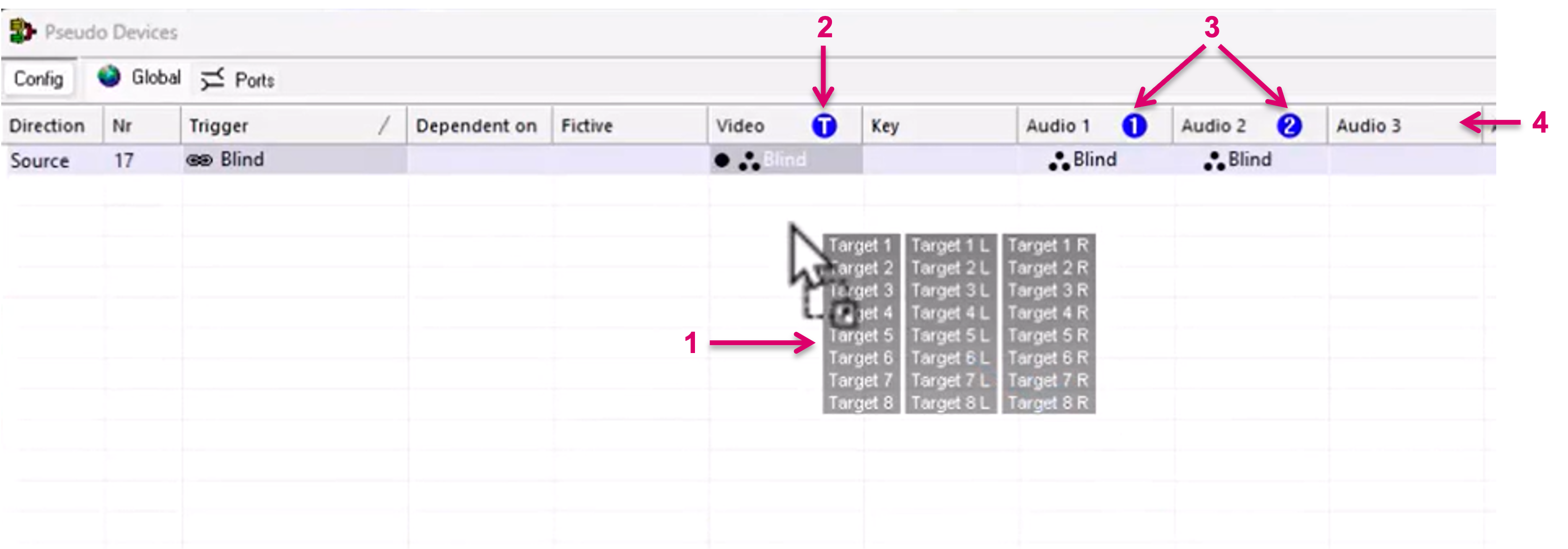
First select the desired Signalpaths from the primary Virtual Matrix view or the Signal Path list (1). Then drag the selected Signalpaths to the Pseudo Device view and hover over the table header row. While still holding on to the dragged Signal paths, hover over the first desired Column (header). Then hit the shift button on your keyboard. The respective column will be marked with a "T" icon (2). Cells in this column will be the target for the following drop operation. If proceeding to other columns and hitting Shift again, these columns will be marked with "1, 2, 3, etc,..." (3). These markers represent also drop-target columns while the numbers mean the order. So, dropping multiple Signalpaths on any position of a table row, the first Signal will be dropped in the cell of column marked "T", the second in the cell of column marked "1" and so on.
Dropping the Signals onto the table-header row (4), the system will implicitly assume a desired "add pseudo device" action. The trigger will be assigned in the marked "T" column.
To deselect a marked column, hover over the header and hit shift again. If deselecting the marked "T" column, this will deselect all other selected columns as well.
To help visibility, the dragged signal bundle is automatically arranged in columns corresponding to the number of marked columns.
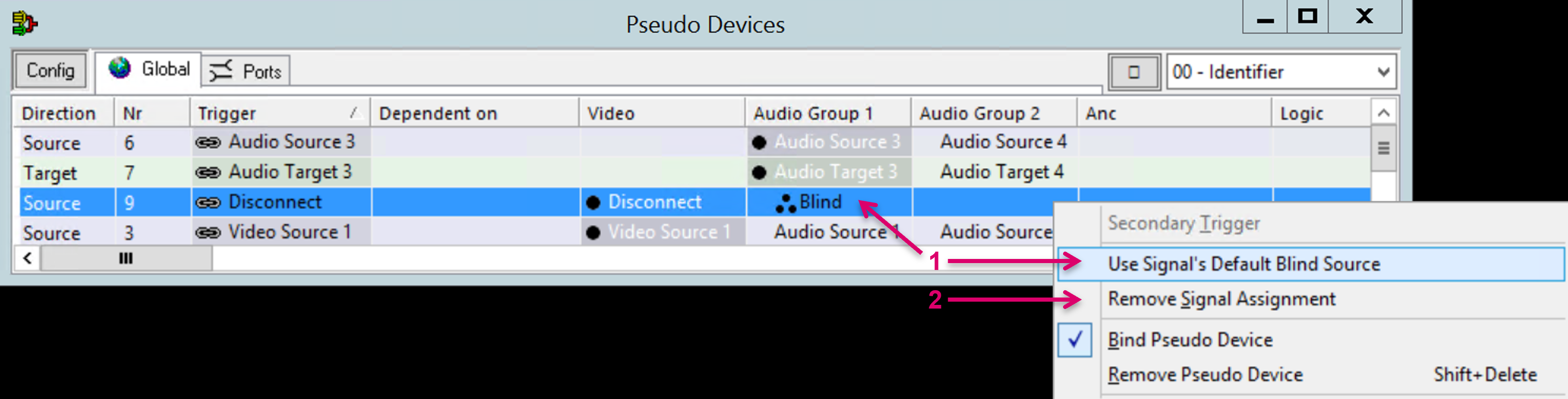
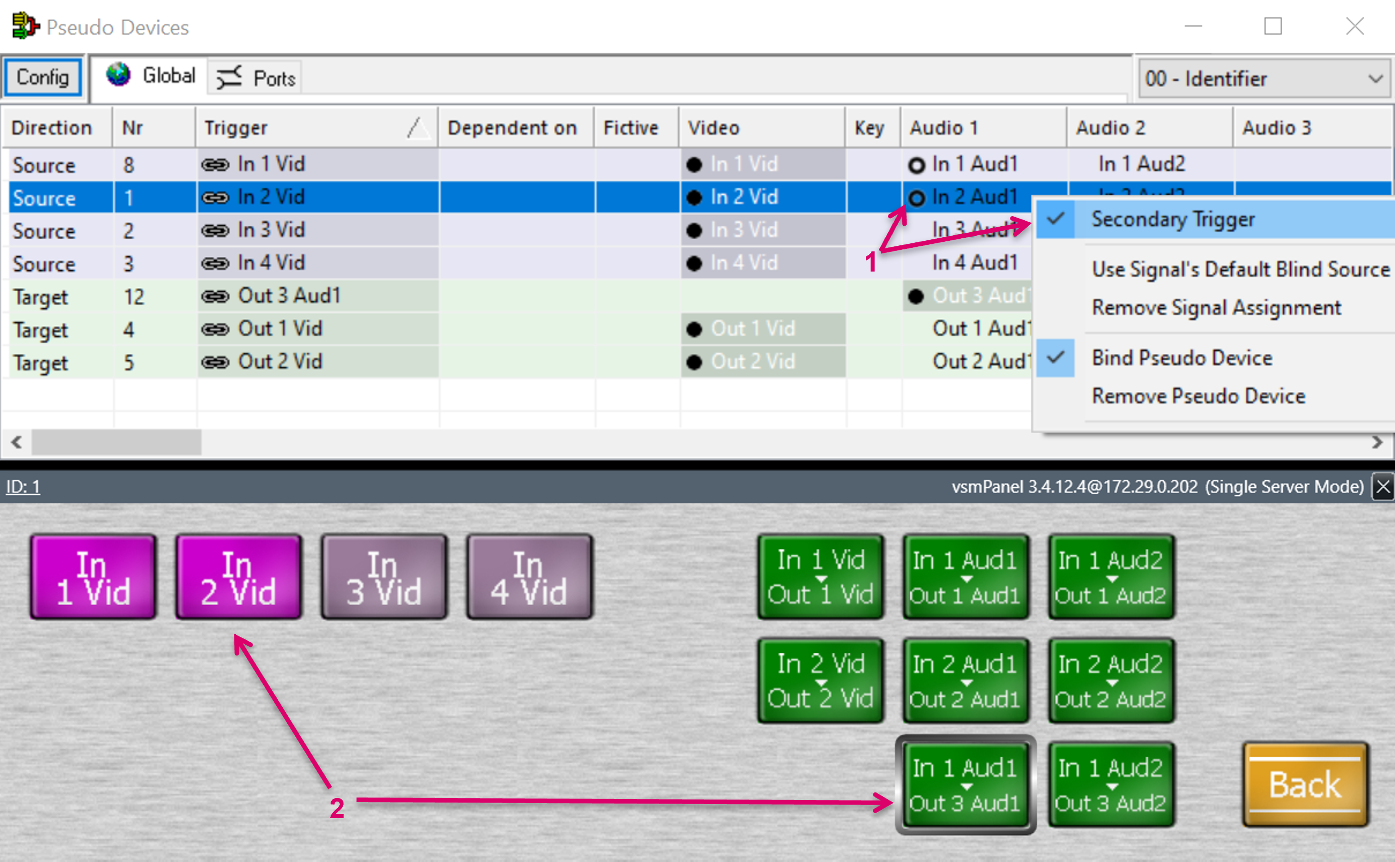
To assign the signal layer-specific Blind signal to a column, just right click on the respective cell and select Use Signal's Default Blind Source. To delete an assignment on a cell, select Remove Signal Assignment (2).
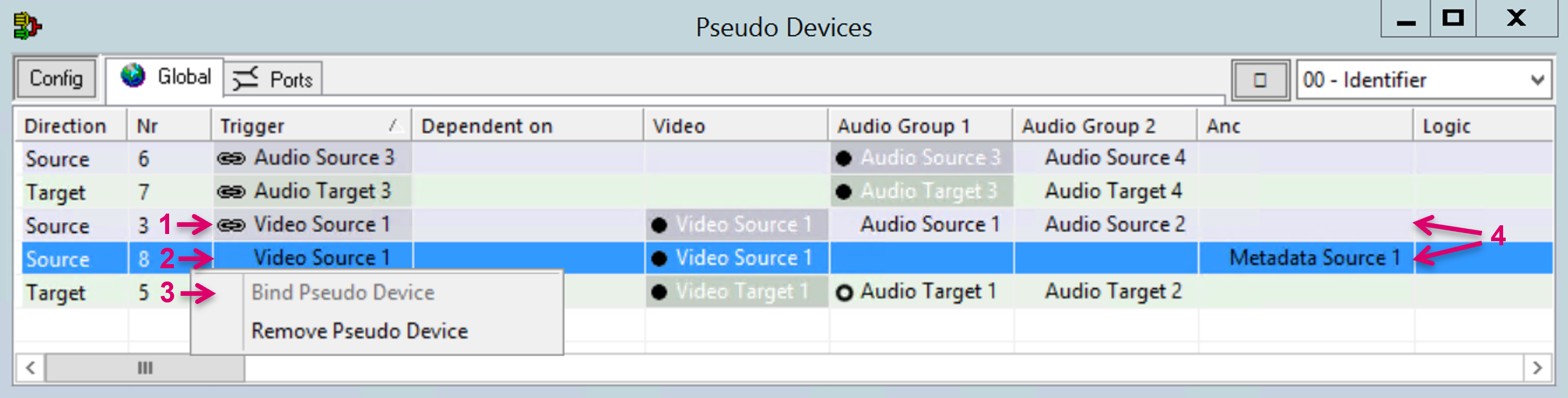
Once a signal is defined as Trigger, a lock/chain symbol appears in the column Trigger in front of the signal name (1). It indicates that this Pseudo Device Signal is the one, considered by the System for internal calculations, e.g., with Dynamic Attachment Scripts. If the same signal is dropped multiple times in separate rows of the list, the lock symbol will only appear on the first dropped instance (2). It is possible to select after which entry of one and the same signal is “bound”. Please note, that the currently locked Pseudo device entry first must be unlocked before the other instance of the same trigger signal can be set to Bind Pseudo Device (3).
If adding the same Trigger Signal multiple times into the Pseudo Devices list, make sure the attachments in the related columns are not conflicting. Means for instance, if there is an assignment in column "Audio 1" of one variant of this Signal, the "Audio 1" column of a second variant of the same Signal must be empty or filled with the identical Signal assignment but never be filled with a contradicting assignment (4).
To delete Pseudo Device entries, select the respective entry and choose the right click option Remove Pseudo Device. The Remove Pseudo Device option will delete the entire Pseudo Device, no matter if executed from the Global or a Group view.

Secondary Trigger
It is possible to assign a Secondary Trigger to a Pseudo Device. The Secondary Trigger allows for Pseudo Device rule execution based on a “set crosspoint action”, even if the primary Trigger Signals may not be compatible. An application example: A Pseudo Device Target is created with primary Audio Trigger. Although it is basically not possible to route a Video Pseudo Device Source with Audio assignments to this Audio Target, if the Audio column of the Video Source was defined as Secondary Trigger, the “set crosspoint action” of this Video Source to Audio Target will trigger the underlying Pseudo Device rule, means Audio to Audio will be routed.
The use of this feature is exclusive to Panel buttons (2). The crosspoint trigger via any matrix view will not consider the Secondary Trigger.
Enable/ Disable Pseudo Device Rules by GPIO
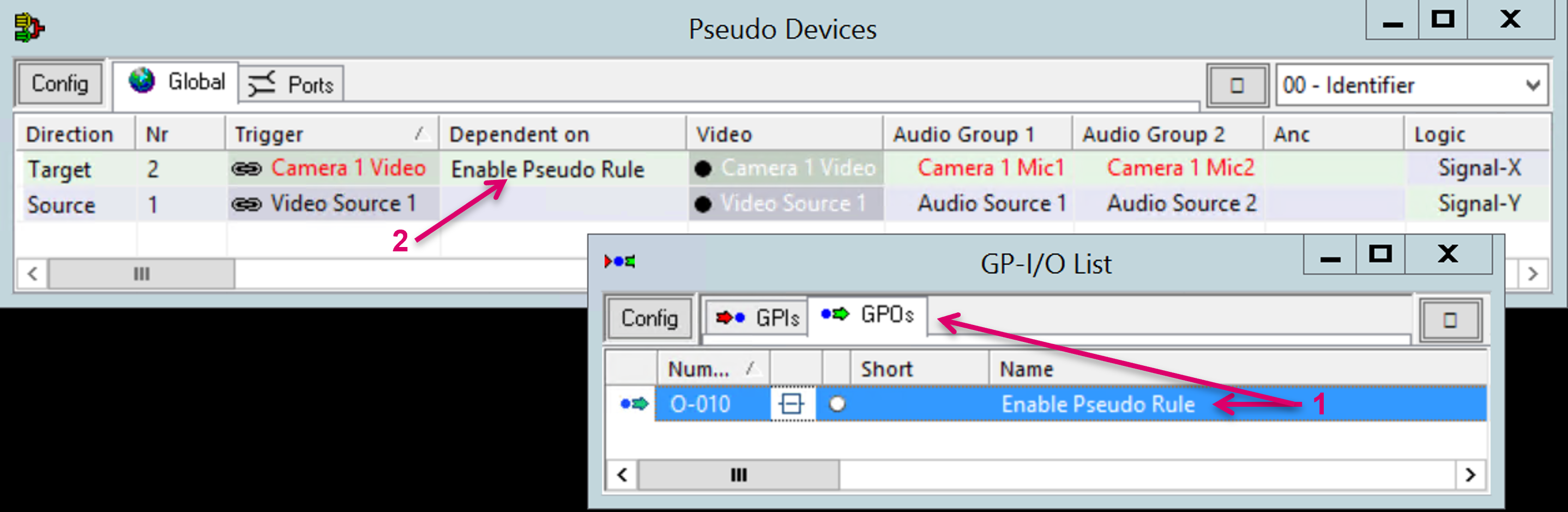
Optional, each Pseudo Device rule can be enabled or disabled separately. To do so, drag any GPI or GPO from the GP-I/O List (1) into the “Dependent on” column and cell of the respective Pseudo Device (2). Consecutive, the respective Pseudo Device rule will only be executed if the assigned GPIO status is True.
Add Pseudo Device Groups
In addition to the Global Pseudo Device list tab (1), it is possible to create Pseudo Device Groups for easier access and administration. Groups allow to select which columns are displayed in the view.
Navigate to the Config tab of the Manage Pseudo Device View, and further to the Groups tab, to Add, Modify, or Remove Groups (1). The displayed order of Group tabs can be changed by selecting a Pseudo Device Group by Name and clicking the up and down arrow keys (2).

When adding or modifying a Pseudo Device Group, a Name and optional Usage/Comment can be set (1). If Pseudo Devices are still showing up in the Global group listing, after being assigned to this custom Pseudo Device Group, can be defined via the checkbox “Hide items in this group from the Global group” (2). Define via the checkboxes which Layer columns should later be displayed in the Pseudo Device list (3).
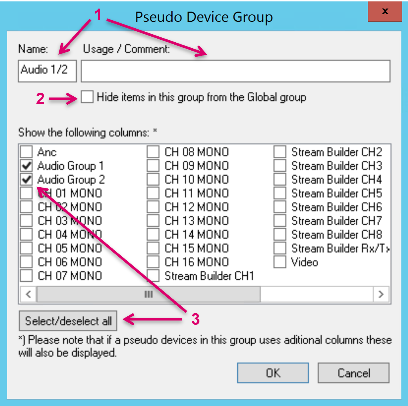
Please note that, even if not selected in this view, if a Pseudo Device is assigned to this group, that has Signals attached in additional columns, these respective columns will also be displayed in the Pseudo Devices View, even if unchecked here.
Any Pseudo Device can be dragged from the Global list (1) and dropped onto the created Group tab (2).
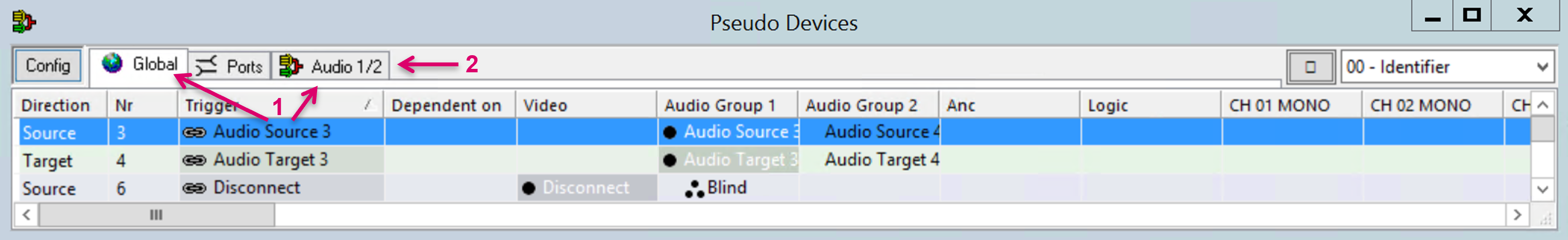
Navigate to the Group tab (1). The dropped Pseudo Device is displayed. If no other columns than the previously selected are used for this Pseudo Device, only the configured columns are displayed (2). If the checkbox “Hide items in this group from the Global group” was checked, the Signals in this Group view will disappear from the Global list.
To remove a Signal from a Group view only, do not use the right click option Remove Pseudo Device. The Remove Pseudo Device option will delete the entire Pseudo Device, no matter if executed from the Global or a Group view. If a Signal is not desired to appear in a Group view anymore, it can be dragged and dropped back onto the Global tab or any other Group tab.
Label Inheritance
Pseudo Devices are also the basis for Label Inheritance where a Pseudo Device Trigger Signal effectively acts as Label parent and its assigned Signal Paths can inherit their label.
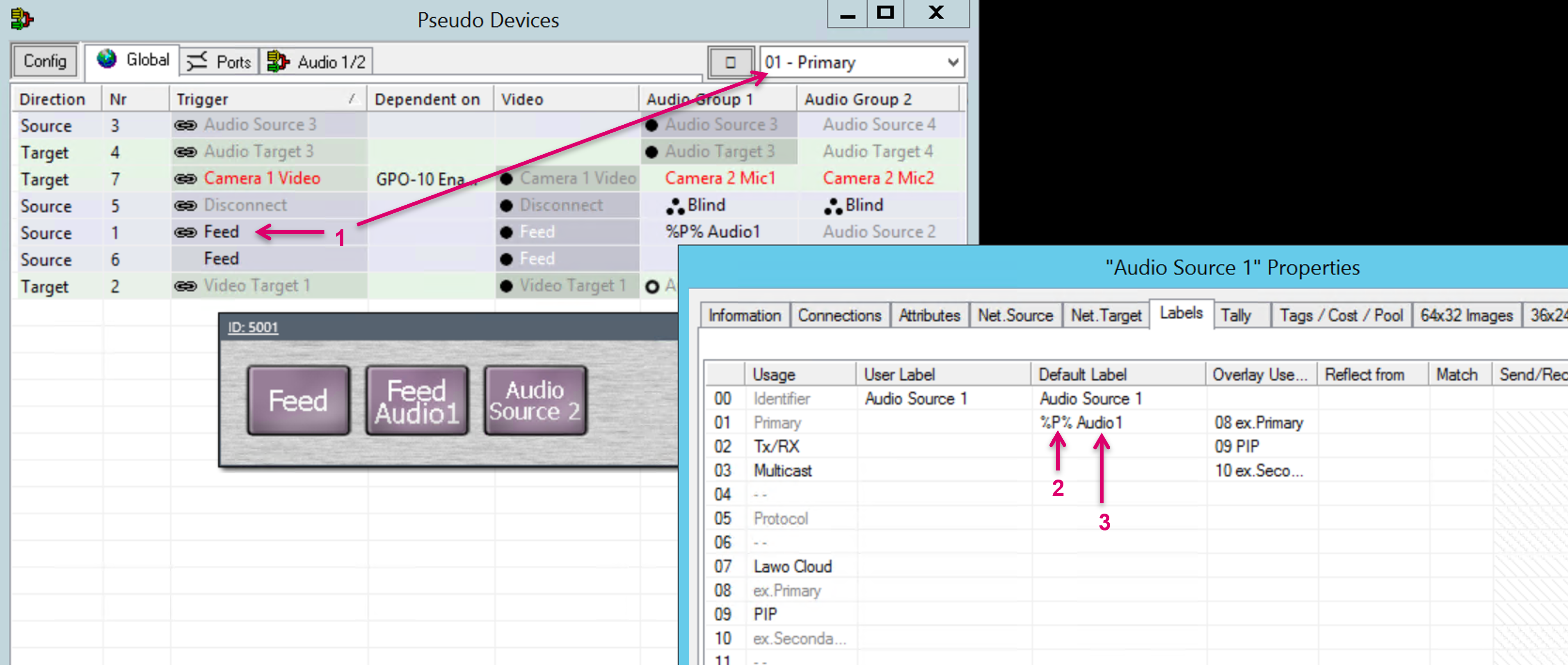
To inherit a label from the “label parent”, the respective label level of the Trigger Signal path obviously must have a label present (1). On the “label child” Signal path, type %P% (2) in the respective label cell. This will immediately pull the Trigger Signal label. Furthermore, it is possible to append additional label information that will be added as well, e.g., Audio1 (3).
Shuffling with Pseudo Device Layers
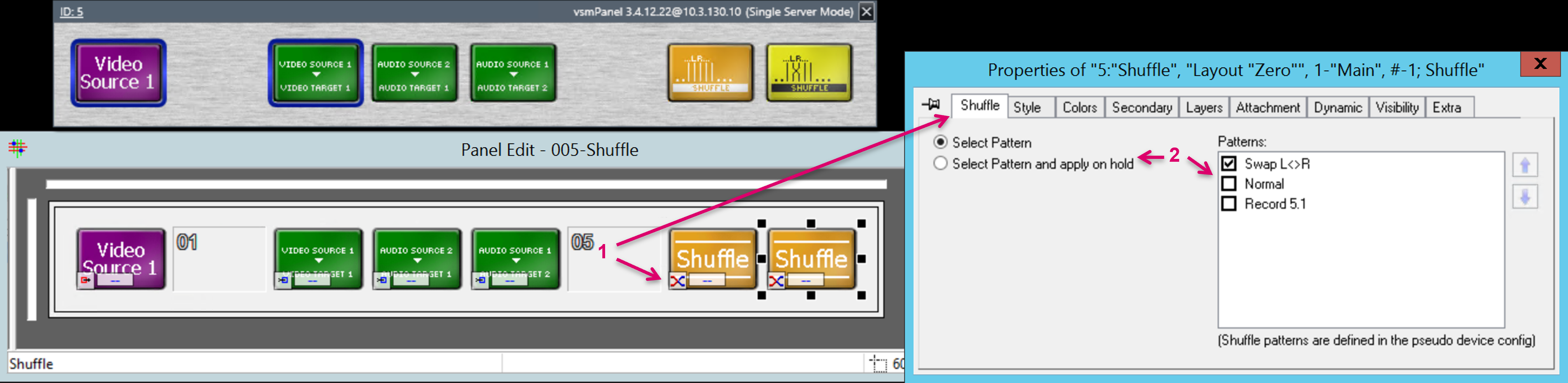
Another feature based on Pseudo Device rules is the Shuffle button on panels (1), that allows to shuffle the Signal assignments when routing a Pseudo device Source to a Pseudo Device Target. In addition to assign the Shuffle button on a panel, a Shuffle pattern must be selected (2).
Patterns can be configured under the Config tab of the Pseudo Devices view. Navigate to the Config tab of the Manage Pseudo Device View, and further to the Shuffle tab (1). In this view you can add New Pattern and Modify or Remove existing entries (2). To modify an existing Pattern or create a New Pattern, select the respective entry (3) and Modify or New Pattern (4).

In the opening view, the Name or Description of Pattern can be set (1). In the Section below the Pseudo Device columns are listed with a Target and Source side.

On the Target side, click on the pin of the respective Pseudo Device column (1) to select what should happen/ be routed to the target if this Shuffle Pattern will be active in the routing process. Clicking on the pin multiple times toggles between “select source pin” and “Blind” (2). If Blind is selected, the Signal Target, that is assigned to the respective Pseudo Device column, will be routed to Blind, even if the routed Source would have a valid Signal assignment in this column.
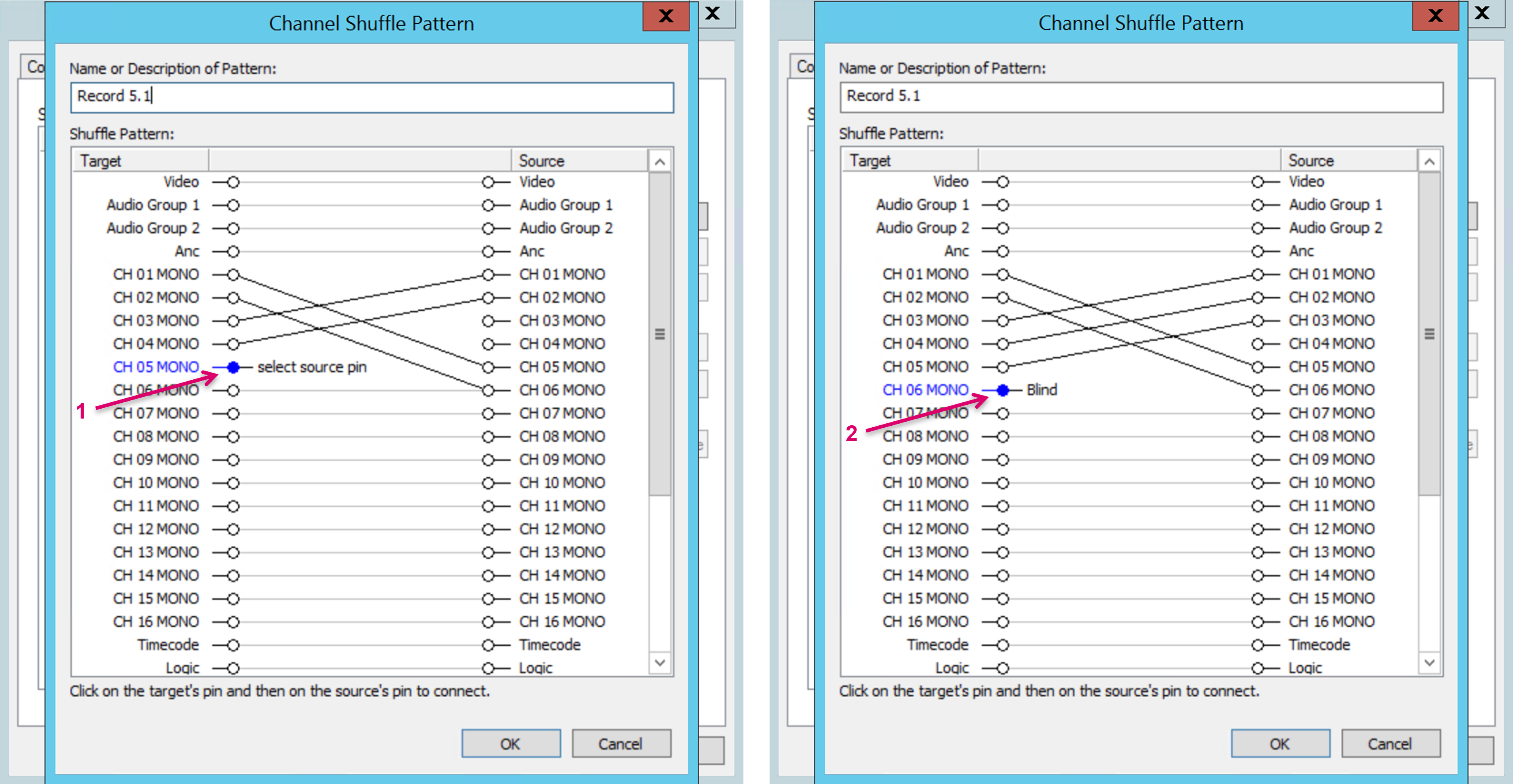
If “select source pin” is displayed (1), a pin on the Source side can be selected after (2). A connective line is displayed (3), that shows the expected mapping and Signal routing of Pseudo Device columns, if this Shuffle Pattern would be enabled and applied in a routing process.
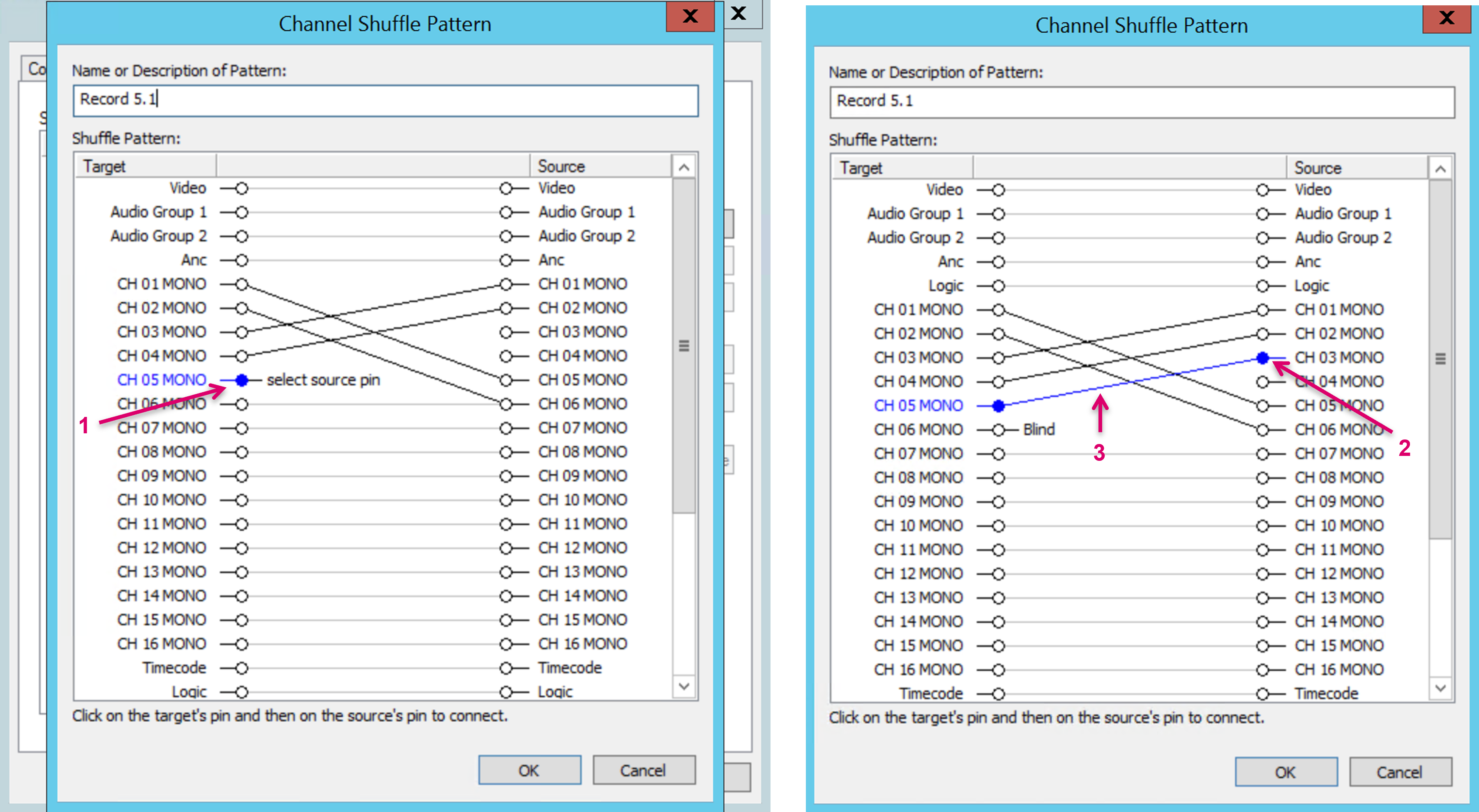
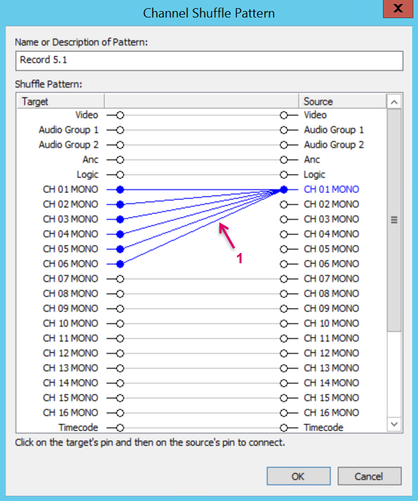
The same Source can be mapped to multiple Target columns (1) while one Target can obviously only be mapped to one Source at a time.
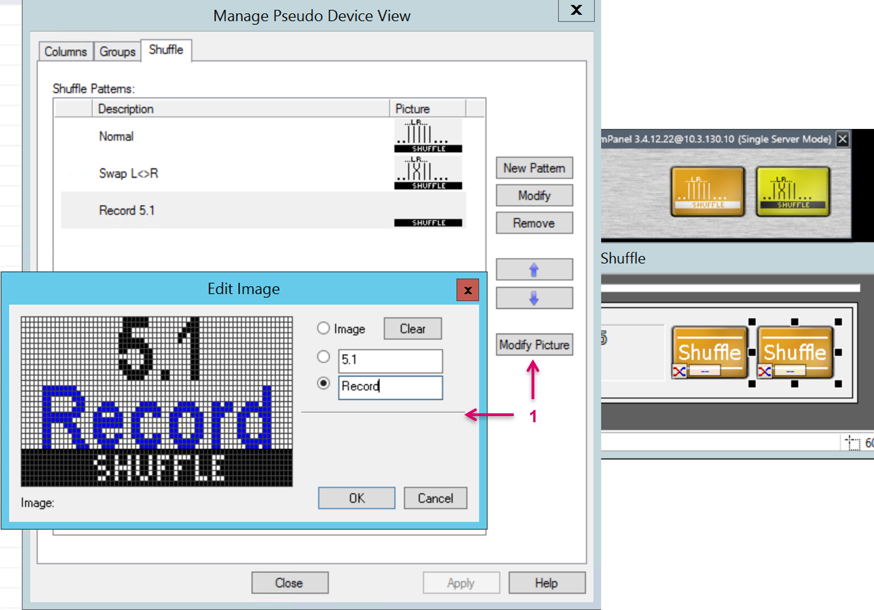
To support the visibility of the underlying mapping on panel buttons, it is possible to assign a describing Text or Button Image to each Shuffle Pattern (1).
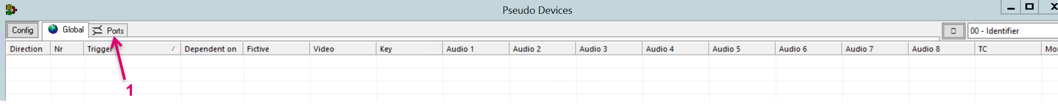
Ports
The PushToTalk (PTT) is a special feature in vsmStudio basically allows to create a virtual Intercom functionality based on Audio Source and Target resources that are accessible, e.g. by an Audio router. An essential part of the PTT configuration is based on specific Pseudo Device rules that can be configured under the tab Ports of the Pseudo Devices view (1).
Like for the normal Pseudo Device configuration, just drag and drop Signal paths from Matrix view or Signal Path List (1). Sources may represent a Microphone and Targets may represent a Speaker input.
GPOs are used to activate Speaker and Microphone resources. Therefore, respective GPOs must be assigned by drag and drop operation from the GP-I/O List (2).
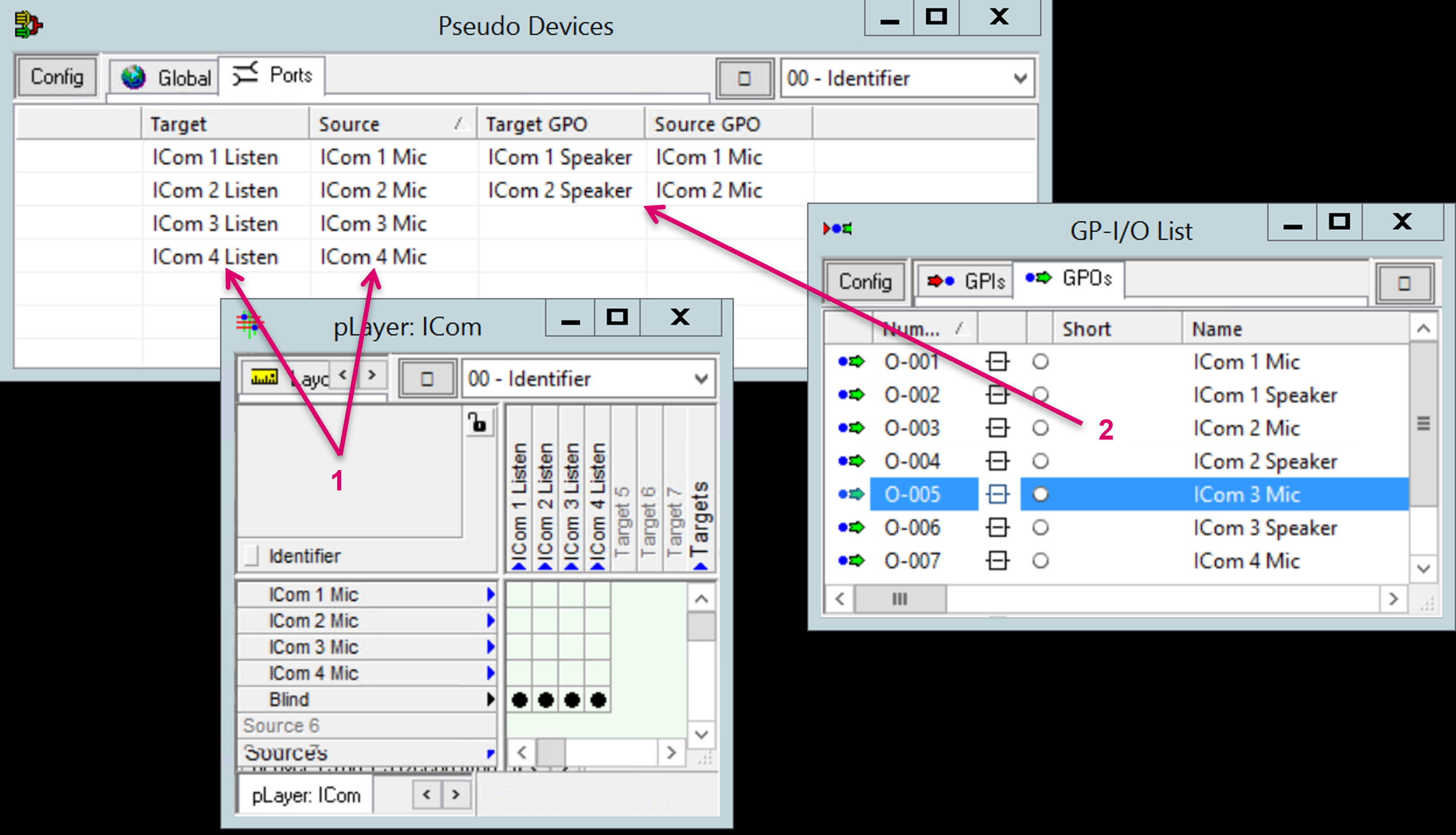
Signal paths that are used in the Ports list and also assigned to the Pseudo Devices list, will be displayed with a colored background (1).

Please note that the configuration of these Signal paths in both lists may interfere and affect the PTT functionality.
Media Essence Filter
The Media Essence Filter feature effectively splits and combines SDP information of various essences to support devices that expect grouped SDP. The underlying logic of this feature is based on Signal paths configured as Pseudo Devices including the respective signal essences. Please refer to the specific Media Essence Filter documentation for further details.