vsmStudio - Master Matrix

Introduction
The master matrix (or virtual matrix) is the consolidation of all vsmStudio's physical routers, mixers, and virtual devices (see Virtual Signals). This virtual matrix allows the user to sort input and output signals independent of their physical assignment.
This chapter covers the configuration of the master matrix.
First Steps
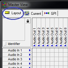
Open the master matrix by clicking on the appropriate button in the main menu bar:
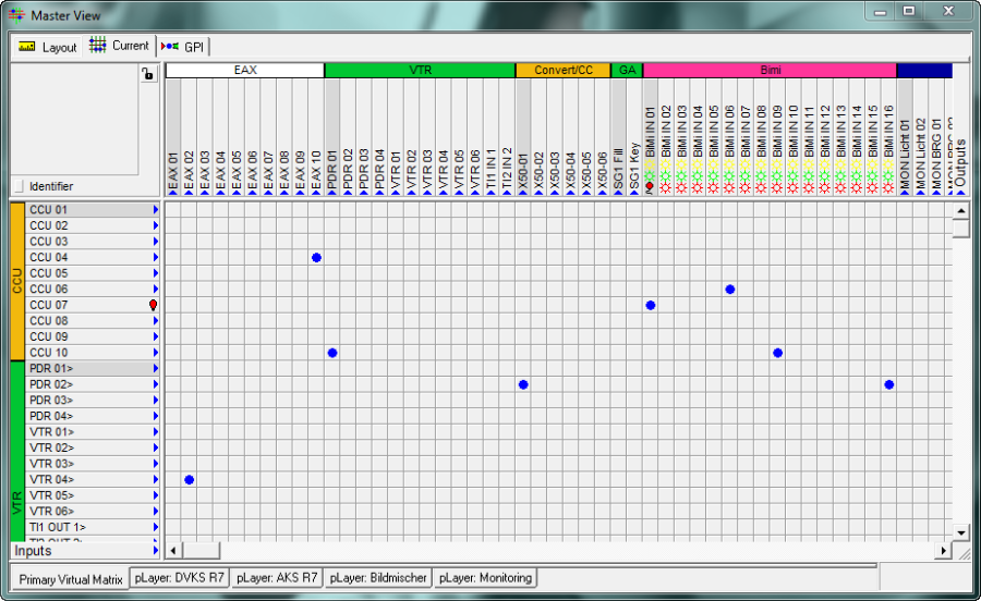
The master matrix opens - you will see the current configuration:
Layout View
To display all signal paths in the master matrix, select them in the signal path list (see Signal Path List) and drag them into the master matrix. To mark all or several adjacent signal paths, select them with the cursor while pressing the Shift key. Multiple individual signal paths can be marked by selecting them with the cursor while pressing the Ctrl key. Drag the selected signal paths into the layout view of the master matrix and drop them there by releasing the left mouse key. The input signals are now placed on the input side and the output signals on the output side. Alternatively, all signals are once copied to the input and then once to the output side. They are distributed automatically to the correct input and output side of the matrix. By quickly pressing the Alt key, they can be dropped individually in their original order.
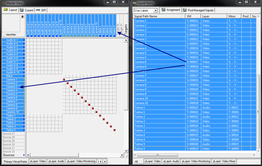
Drag and drop of signal paths
Please note: the text will appear in red if tie-lines are only set up on one side of the master matrix. It shows that it is not possible to set crosspoints until tie-lines have been set up on both sides of the X/Y matrix. Generally, it is not possible to switch crosspoints with tie-lines in the master matrix (See chapter 5.5.1 Dynamic Tie-Line Management).
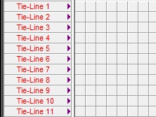
Red marking of tie-lines on one side of the master matrix
Arrangement of Signal Paths
In the layout view, the arrangement of signal paths can be chosen freely by selecting the signal in question and dragging it onto a free position. Using the same selection methods as described above, it is possible to select the required signals while pressing either the Shift or Ctrl key. Whle the layout view is selected, it is not possible to switch any crosspoints.
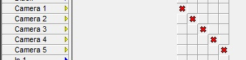
Invalid Crosspoint Switches
A red cross marks sources and targets that lie on the same layer but do not allow for a crosspoint switch. This occurs, for example, with a virtual signal (see Virtual Signals), which is designed to act as both, source and target. The respective crosspoint is marked with a red cross.
Jump Points
By right clicking on a signal, a window opens offering the following options:
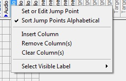
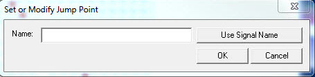
Jump points can be created to find signals or signal groups more easily. Right click on a signal and select the option Set or Edit Jump Point. A new window opens. There, the title of the jump point can be entered, edited or set by using the signal name.
The jump point is now ready to be used: just right click on any signal in the master matrix.
This opens a window in which the signal's jump point can be selected, while the view of the matrix automatically jumps to the corresponding signal:
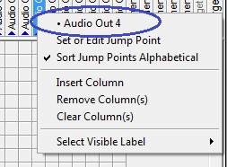
Sort Jump Points Alphabetical is checked by default to allow multiple jump points to be listed alphabetically in the window above. Left click on Sort Jump Points Alphabetical to deactivate the function.
Insert or Remove Signals and Columns
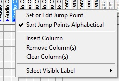
Options in layout view
To insert a column above a signal, stay on Layout view and right click on the signal in question to open a new window, then left click on the Insert Column option in this window. Clicking Remove Column(s) will prompt a pop-up requiring a confirmation, after which the selected column will be deleted from the matrix. It is also possible to delete multiple columns at the same time (select multiple adjacent columns while pressing the Shift key or separate columns while pressing the Ctrl key).
Please note: the selected columns will be deleted even if signals are placed on them.
The selected signal is deleted from the virtual matrix by left-clicking Clear Column(s) (and the confirmation of a prompt). It is again possible to delete multiple signals from the matrix at once.
Displayed Label
Left-click on Select Visible Label to open a variety of different labels (see Labels):
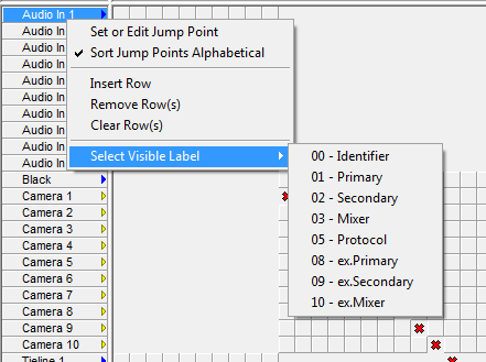
Label settings affect all signal paths in all three views of the master matrix.
They can be changed for the entire matrix in the small grey square on the label display (see Label Display).
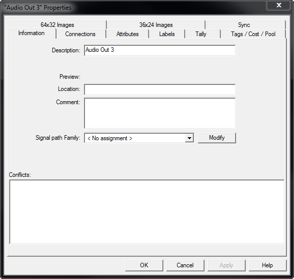
Signal Path Properties
Signal path properties can be displayed by double clicking on a signal (see Edit Signal Paths).
Current View
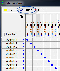
The Current mode is the second tab of the master matrix. It is located in the top left of the master view. In this mode, the switching of crosspoints is possible. The Current view also offers an overview over recently set crosspoints.
Switching Crosspoints
To enable crosspoint switching in the Current view, select the small lock symbol. This will unlock the switch view.
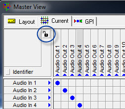
If switching is attempted without first unlocking the switching view, the lock symbol will blink repeatedly.
Please note: before crosspoints can be set, the switched layers must be assigned to a router (or to the VSM Dummy X-Switch) so that vsmStudio receives feedback through the switch.
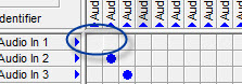
Blue dots in the area connecting input and output signals on the matrix indicate set crosspoints.
Crosspoint Properties
Coordination of Crosspoints
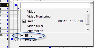
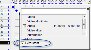
Right-click on any field in the matrix to open a window showing the coordinates of the selected crosspoint on the connected layer as well as other properties.
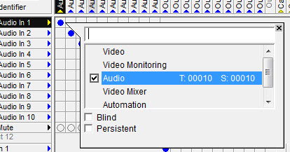
Comments about this crosspoint can be added in the blank, white field. The numbers after T (target) and S (source) show the position of source and target on the respective layer.
Display of Layers
All available layers are shown below the comment field. The check mark shows the layer on which the selected crosspoint is located. If the check mark is removed, the crosspoint cannot be set any longer.
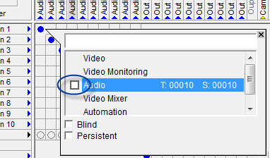
Removed checkmark in layer view
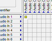
In the matrix, this is represented by an empty field that cannot be selected.
In layout mode (see Layout View), this is shown with a yellow cross.
Blind Source
If Blind is ticked, the crosspoint becomes a blind signal source.
This is signalled by an empty dot with a black frame.
Permanent Switch
If Persistent is ticked, only the specific source can be switched onto this target.
Permanent crosspoint
As a result, all other fields in this column are empty and cannot be selected, and a small P appears below the signal name.
Locking a Target
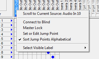
Target options in Current View
The window that opens when right-clicking onto a target in the Current view offers two more options besides Select Visible Lable and the Jump Point functions discussed above: Scroll to Current Source and Master Lock (right-clicking onto a source signal will open a window with jump point functions and Select Visible Label, see Jump Points).
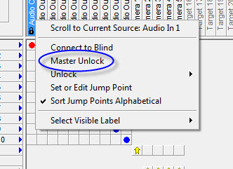
While in Current view, the function Scroll to Current Source scrolls to the source switched to the selected target. Master Lock locks this target for all switches. This is shown with a small lock symbol located just below the signal name.
![]()
Locked target
To release the master lock, right-click onto a target and select the function Master Unlock.
Display of Crosspoints
Crosspoints with different signal types are colour-coded and distinguished by different symbols.
Physical Crosspoints
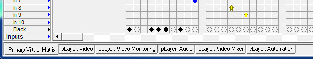
In Current view, a blue dot indicates a physical crosspoint:
![]()
A black dot indicates that a target is switched onto a black signal:
![]()
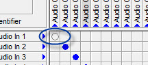
An empty circle indicates a blind signal source (see Blind Source):
![]()
Crosspoints with Virtual Signals
A yellow arrow indicates a physical source switched onto a virtual target:
![]()
The yellow rhombus indicates a virtual source switched onto a physical target:
![]()
A physical crosspoint set using a virtual signal (that is a physical source onto a physical target using a virtual signal) is indicated by a yellow circle with blue outline:![]()
A yellow circle with black outline indicates a physical target switched onto a black signal using a virtual signal:
![]()
Crosspoints with Tie-Lines
In Current view, tie-lines are shown as grey rhombi, not square fields.
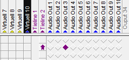
A purple arrow indicates a source switched onto a tie-line. If the signal is switched onto another layer with a tie-line, the crosspoint is marked with a purple rhombus.
Locked Crosspoints
A red dot indicates a locked crosspoint (see Locking a Target). It can only be unlocked by the controlling device that executed it, or with a master unlock.
![]()
Crosspoints with Loop-Through Devices
If a source is routed first to a loop-through device and then to a target, the crosspoint is displayed as a blue rhombus.![]()
ERROR
Linked Signals
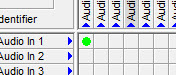
In Current view, one signal following another is highlighted in bright green:

Inverted Switching
It is possible to configure inverted switches for certain sources and targets (see Special Settings). This means that the switch behaviour of the layer (see Switch Behaviour of the Router) is changed for pre-defined crosspoints: For example, if the switch behaviour of the layer was defined as 1:n, it is still possible to switch crosspoints 1:1.
These crosspoints are indicated by a change of background colour in the matrix: inverted switching in an area is indicated by areas with blue background. A grey background indicates inverted switching of this source or target.
![]()
Inverted switches
Tally Display
In the master matrix, tally is indicated by coloured suns with respect to the target:
If tally is activated, the suns are replaced by coloured lamps. These indicate that the source currently sends tally. The source switched onto this target is marked with light bulbs of the same colour as the tally colour.
If the source with tally is switched onto multiple targets, the tally is passed on. This allows all switched targets to receive tally. A passed-on tally is indicated by coloured rectangles.
Active Tally
GPI View
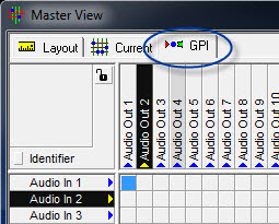
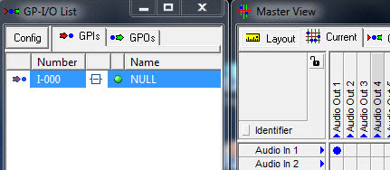
Connection of a Crosspoint with a GPI
The GPI mode allows the connection of a crosspoint with a GPI (see GPIOs). If a GPI is selected in the GPIO list and dragged onto a crosspoint, this GPI logic is placed on top of the crosspoint.
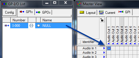
Drag and drop GPI onto crosspoint
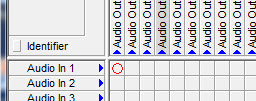
The crosspoint will now be set automatically when the GPI is set.
Crosspoint triggered by GPI
In GPI view, this is indicated by a red circle:
Connection of a GPO with a Crosspoint
In turn, it is also possible to connect a GPO with a set crosspoint. Simply drag the crosspoint in question from the GPI view onto the GPO in the GPO-I/O list.
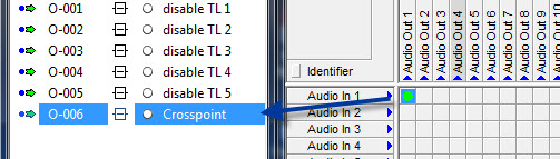
Drag and drop crosspoint into GPO
Setting the crosspoint will now automatically result in the execution of the connected GPO logic.
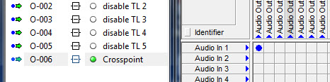
Setting GPO by setting a crosspoint
In the GPI view, this is indicated by a green crosspoint:
Label Display
The signal name used as identifier during the set-up of a signal path is shown in the master matrix by default.
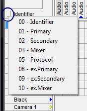
This can be changed by clicking onto the small grey square next to the currently shown label (Identifier). This opens a tab with various label options that can be shown as signal name in the master matrix.
Identifier
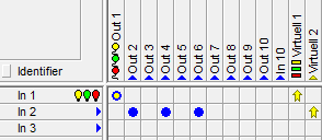
Layer and Position Display
It is possible to select other matrices on the bottom right of the master matrix to the right of the primary virtual matrix. These represent the signals of all available layers (see Layers).
Layer display
The physical layers hereby indicate the actual assignment of the routers. Signals can be arranged arbitrarily on the virtual layers (see New Virtual Layer).
Source and target display
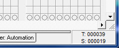
In all three views, the position of the currently selected crosspoint's sources (S) and targets (T) is shown in the bottom right corner of the master matrix.
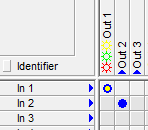
Display of Different Signal Types
There are various signal types that are displayed differently in the master matrix: physical signals, virtual signals, and tie-lines (see Signal Paths). They are set apart by different colour-coding.
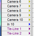
Physical signal, virtual signal, and tie-line
In general, a physical signal path is indicated by a blue arrow and a virtual signal by a yellow arrow in all three views of the master matrix. A tie-line is indicated by a purple arrow and purple font.