vsmStudio - Communication Port Management

Introduction
In order to communicate with attached devices and systems, and to allow for control and monitoring, the respective protocol has to be chosen, and Communication Ports have to be created.
A valid ControlPort license is mandatory for every single, configured and to be enabled device connection (IP address/Port), not only per created Communication Port. UMD/Tally protocol port connections, e.g. TSL, are currently excluded from this rule while being covered by the base license. This applies to each Server in the Cluster. ControlPort licenses are part of the general vsmStudio license file.
With release 25.2.1 the configuration and management of Communication Ports changed in multiple aspects. Changes done to the configuration of the communication ports are now synchronized at runtime with all other servers in the cluster.
Please note that mapping files, based on the Layer to the Communication Port-assignment of e.g. Ember matrices, are not yet synchronised. These mapping files are created and can be found in the Mapping folder of the local Server, on which the assignment was executed. These mapping files must be copied manually to the other Cluster members.
Initial Migration after updating to a vsmStudio version including the new port management
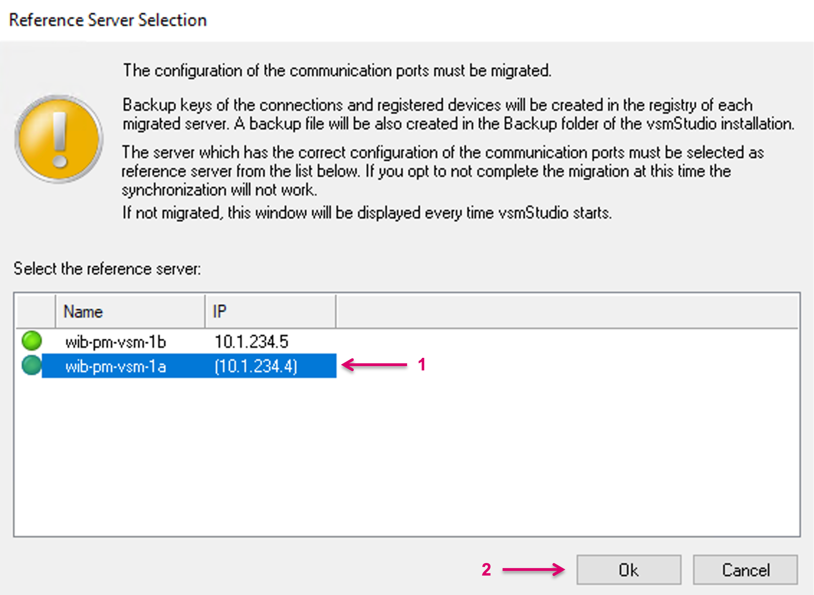
When starting a vsmStudio version, that includes the new port management, for the first time, the configuration of the communication ports must be migrated. Therefore, you will be prompted, via pop-up window, to select one reference Server within the cluster (1) and start the migration. This is a one-time action for the migration process, afterwards any change to the Communication port configuration, initiated from any of the cluster servers, will be synced across the whole cluster, runtime. While the user has the possibility to cancel the migration process, the reference server selection dialog will be prompted again, and at each startup, if this server was not yet migrated and there is also no other server in the cluster, that was already migrated before.
To proceed with the migration process, confirm with Ok (2).
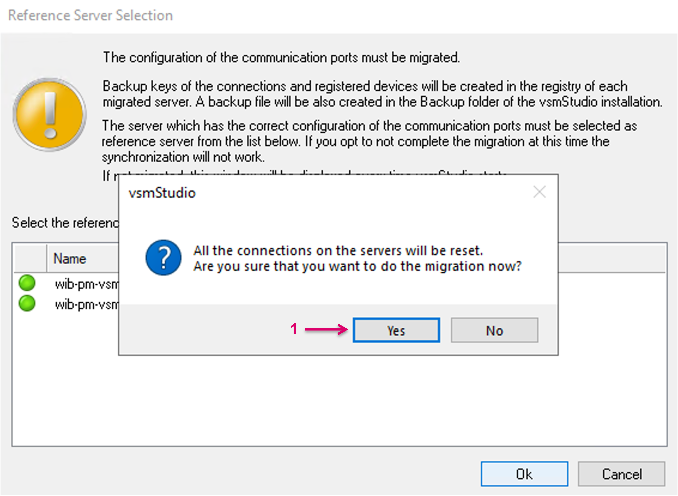
The migration process includes a reset of all Server connections, in order to proceed you will be prompted to confirm with Yes (1).
A backup file is created on each migrated server in the Backup folder of the vsmStudio installation folder. The file can be opened using the "Import" option available on the "Manage Communication Ports" window. Confirm and close the notification window with Ok (1).
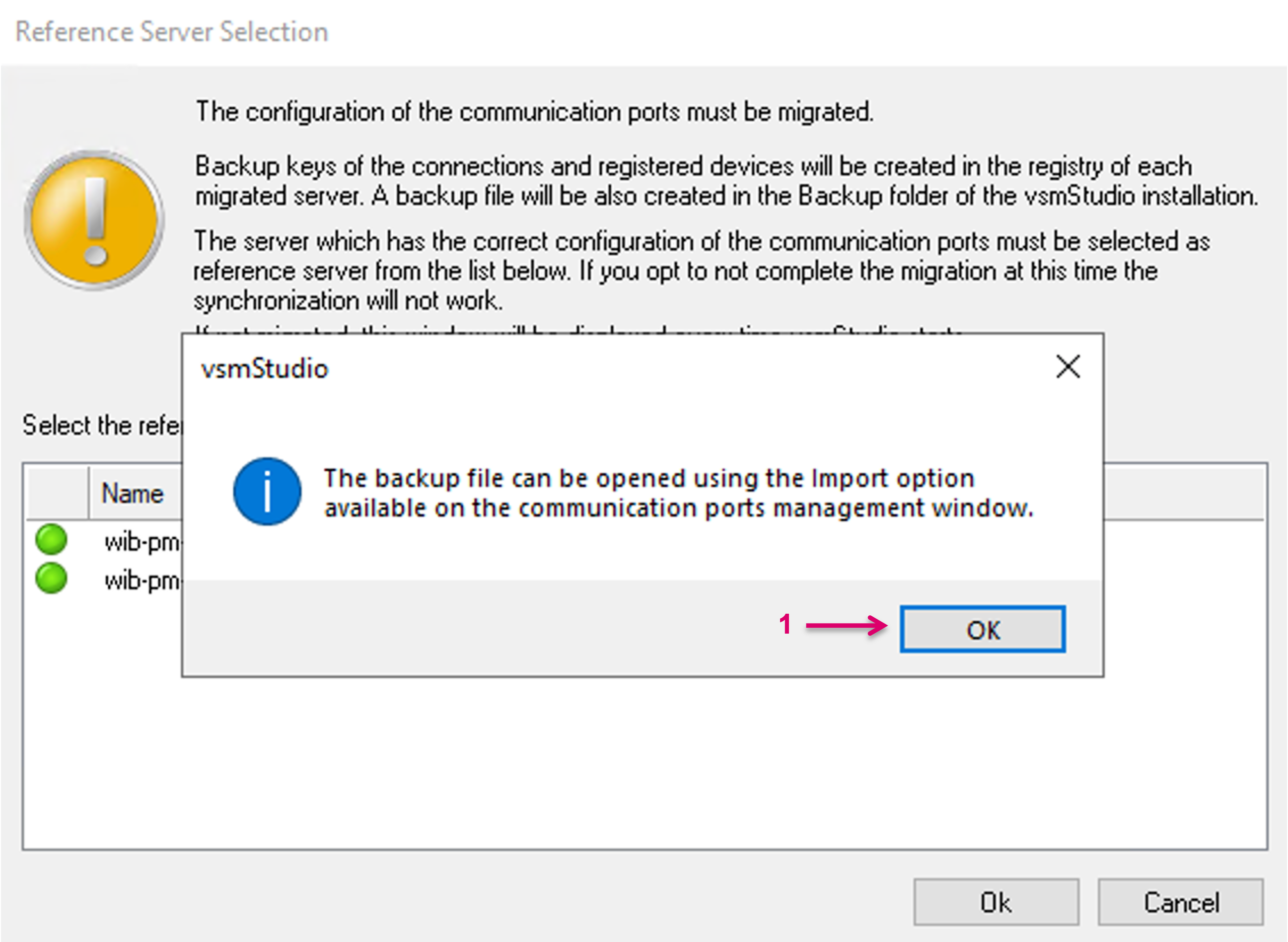
Backups of the "Connections" and "Registered Devices" keys are also created in the registry.
The Manage Communication Ports view
Navigate to the Manage Communication Ports view via the respective icon on the main toolbar.
![]()
An overview of the Manage Communication Ports view:
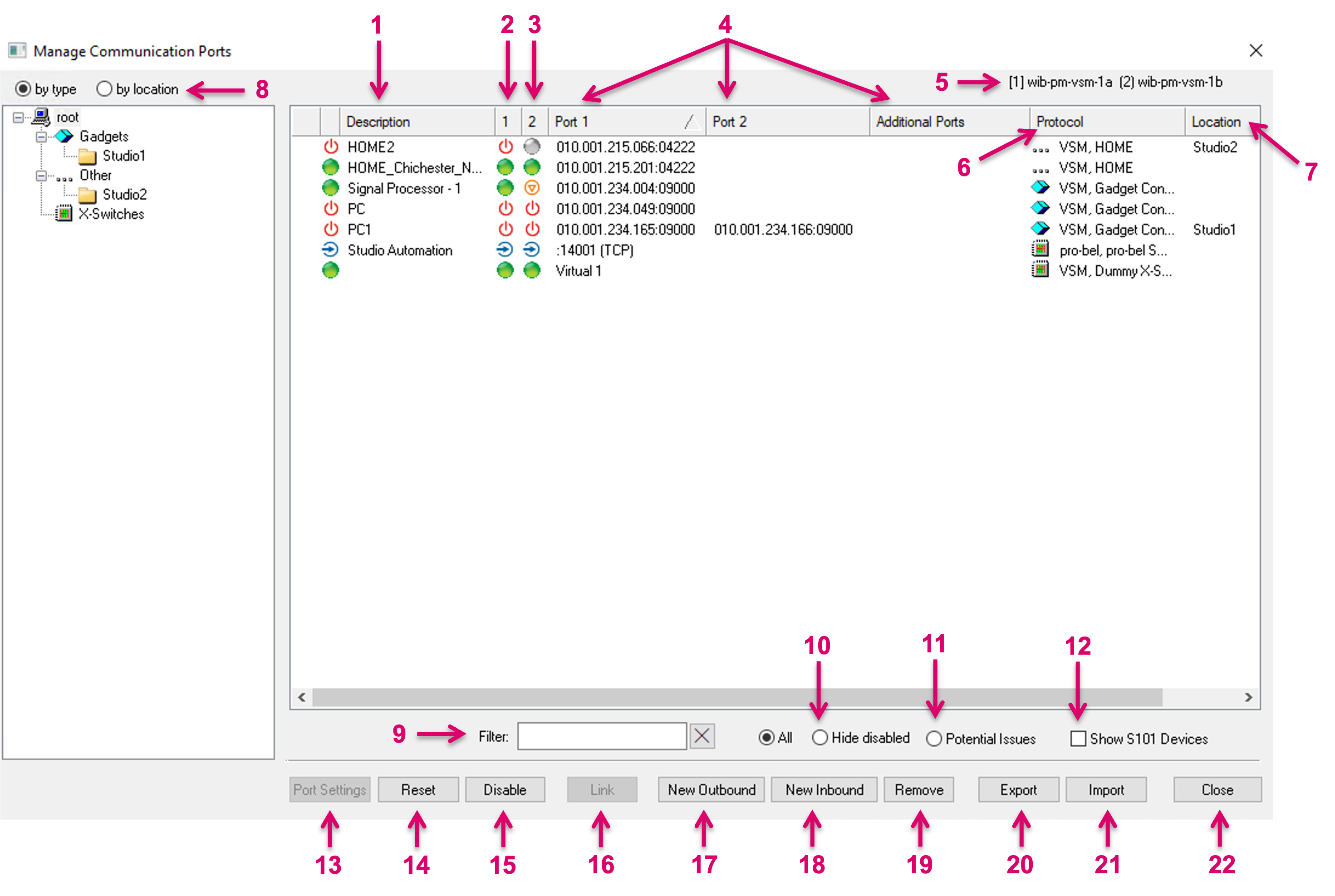 1 – Descriptive name for the respective port
2 – Connection Status Server 1
3 – Connection Status Server 2
4 – IP Addresses of connected device
5 – Available Cluster Servers. Square brackets indicate current Primary Server.
6 – Selected Protocol for respective device connection
7 – Assigned Location
8 – Select window view by type or by location
9 – View filter: List only those entries, that match a given string, as entered
10 – View filter: When set, only active connections will be displayed
11 – View filter: When set, only the connections which are active but not displayed "green" will be displayed
12 – Show S101 Devices (vsmGear)
13 – Enter Port Settings of any selected Communication Port (alternative to double click on a specific Communication port in the list above)
14 – Reset one or multiple selected Communication Port(s). With no selection, All Communication ports are addressed)
15 – Disable (or Enable) one or multiple selected Communication Port(s)
16 – Link selected Communication Port(s) (only supporting legacy configurations. Now, multiple IP addresses, that are assigned to one communication port are now implicitly linked.)
17 – Create a new Outbound port
18 – Create a new Inbound port
19 - Remove one or multiple selected Communication Port(s)
20 - Export one or multiple selected Communication Port(s) incl. settings to file. With no selection, All Communication ports are addressed)
21 – Import one or multiple selected Communication Port(s) incl. settings from file.
22 – Close window
By double-click on any of the already existing entries in the Communication Port list you can enter the respective Port settings dialogue.
Port Monitoring, Status and Indicators
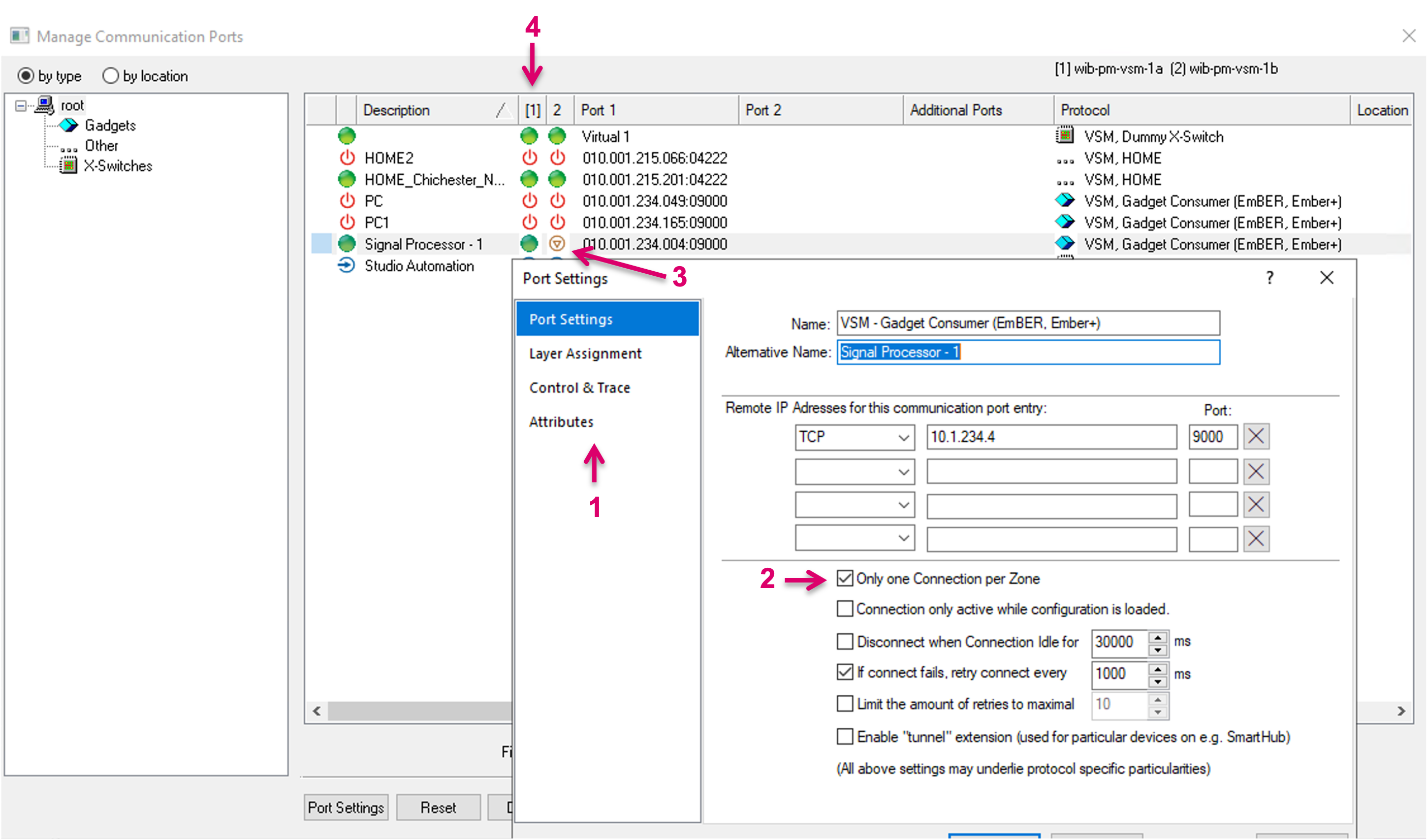
The Manage Communication Ports window allows to monitor the connection state of configured protocols via the respective Properties (1). For instance, an active “Only one Connection per Zone” setting on the local Server (2) results in a specific icon on the second Server in the cluster (3), indicating that this Connection is not active as long as the local Server has a valid connection. The current primary Server is marked with brackets around the ID in the respective Column header (4).
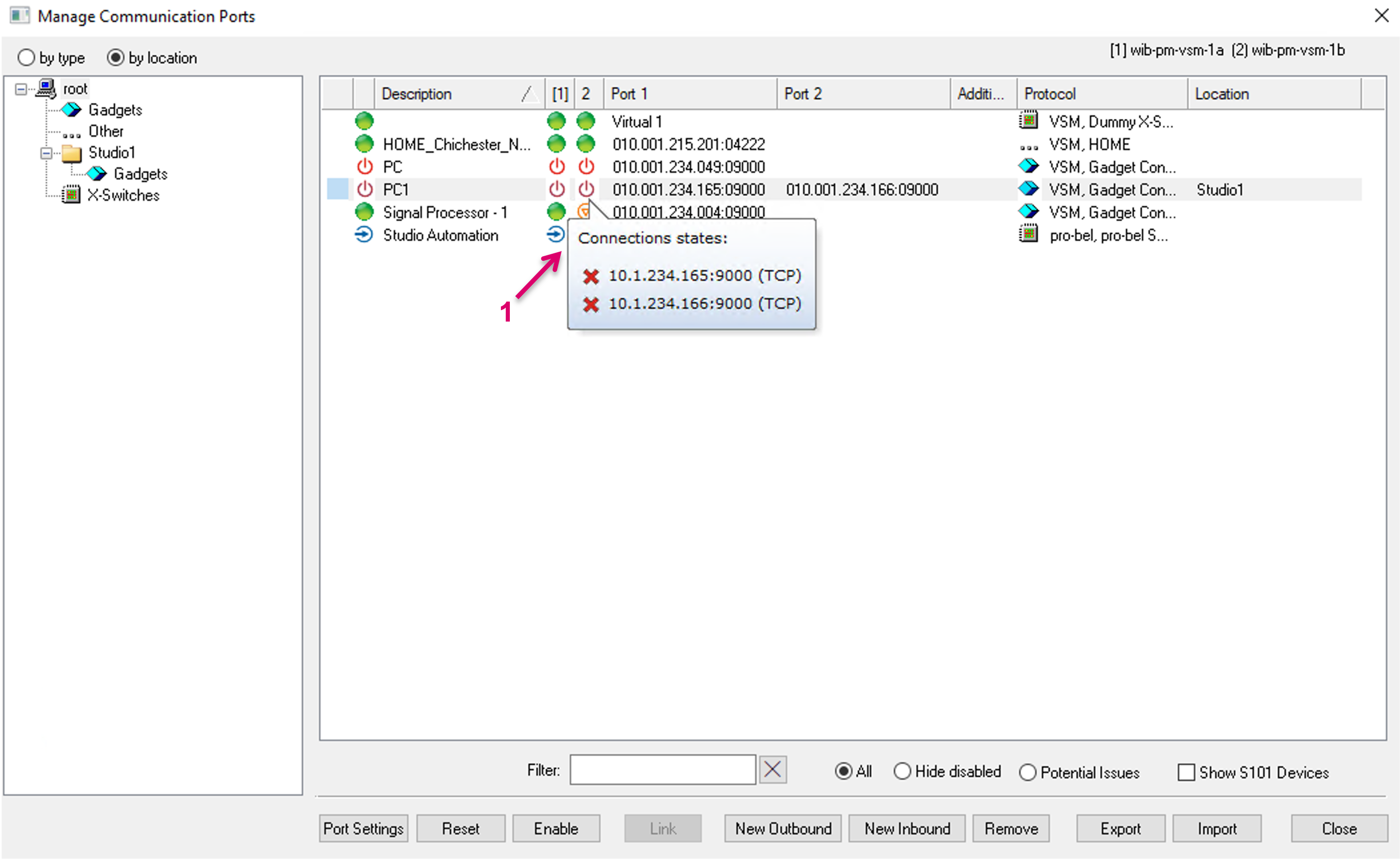
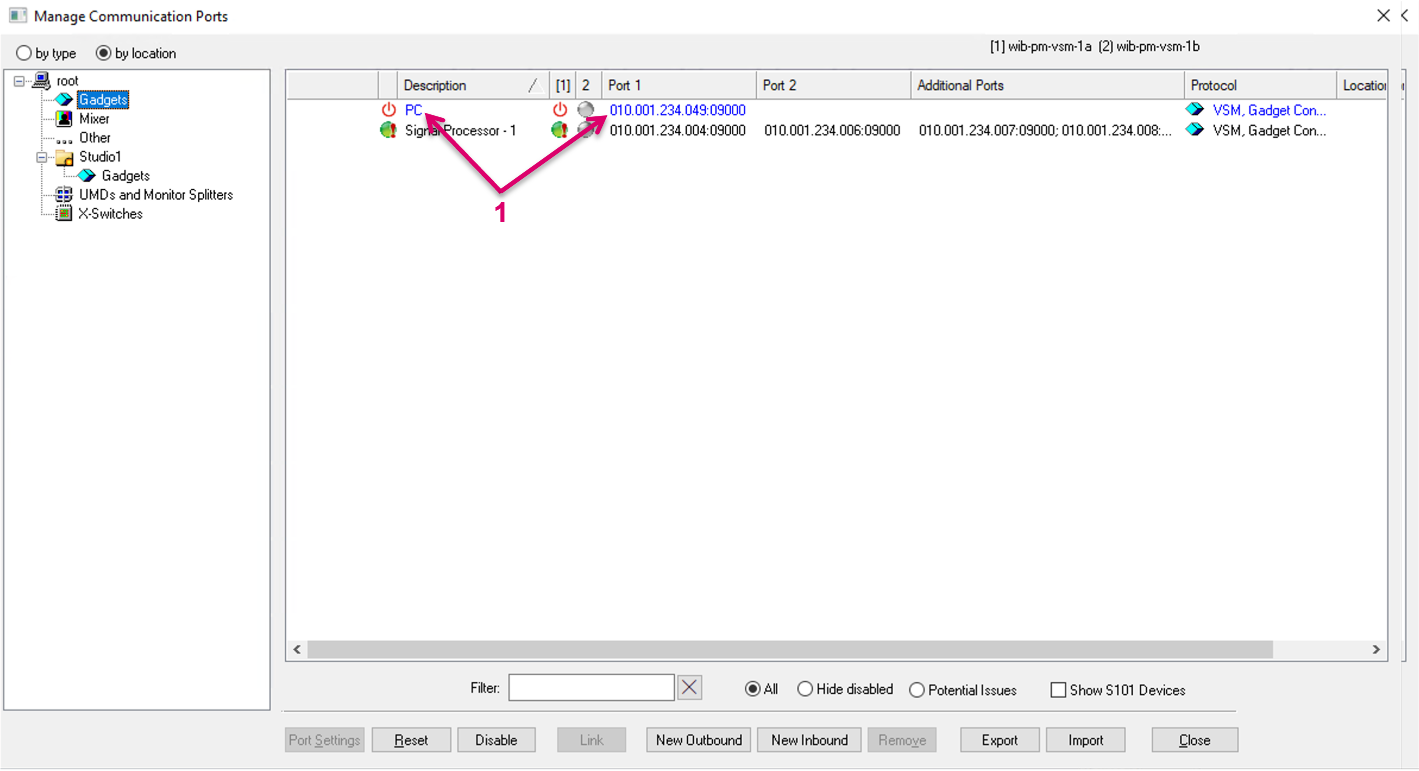
If more than one IP address is assigned to one Communication port, the displayed port status is aggregated from all connections. Hovering over the Status cells of the cluster Servers, more detail is shown in a pop-up window (1).
The symbols in front of the listed ports have the following meaning: | |
| A connection is confirmed and operating. |
| Connection is operating but not all associated connections have valid communication. |
| A connection is confirmed but there is no valid communication. |
| A connection is confirmed, but there has been no communication in the last 15 seconds. |
| A connection is being established and pending. |
| A renewed connection is being established and pending. |
| A delayed connection is being established. |
| Connection failed. |
| Connection is disabled. |
| Connection is on standby (Only one Connection per Zone). |
| Connection is deactivated through a GPI. |
| No Communication Port license available. |
| Port has actively stated that it is the passive connection in a linked set or connection. It is situational when and if that happens and therefore the icon may vary, e.g. at times also the orange dot could be displayed. The result in terms of status and functionality is the same. |
| Inbound port (not showing any Connection status). |
| Linked Connections. |
Hide Server Status
The "Manage Communication Ports" window contain a status column for each server in the zone.
The actual status column will display the global state of each port. The global state is the "best" state of the connection's state from all the servers (e.g. if the connection is operational (green) on one server and offline on the other server(s), the global state will still be operational (green).
The Server status columns which are not relevant and won't affect the global connection state, can be hidden. The respective Server columns will then not show any more in the Port Management view.
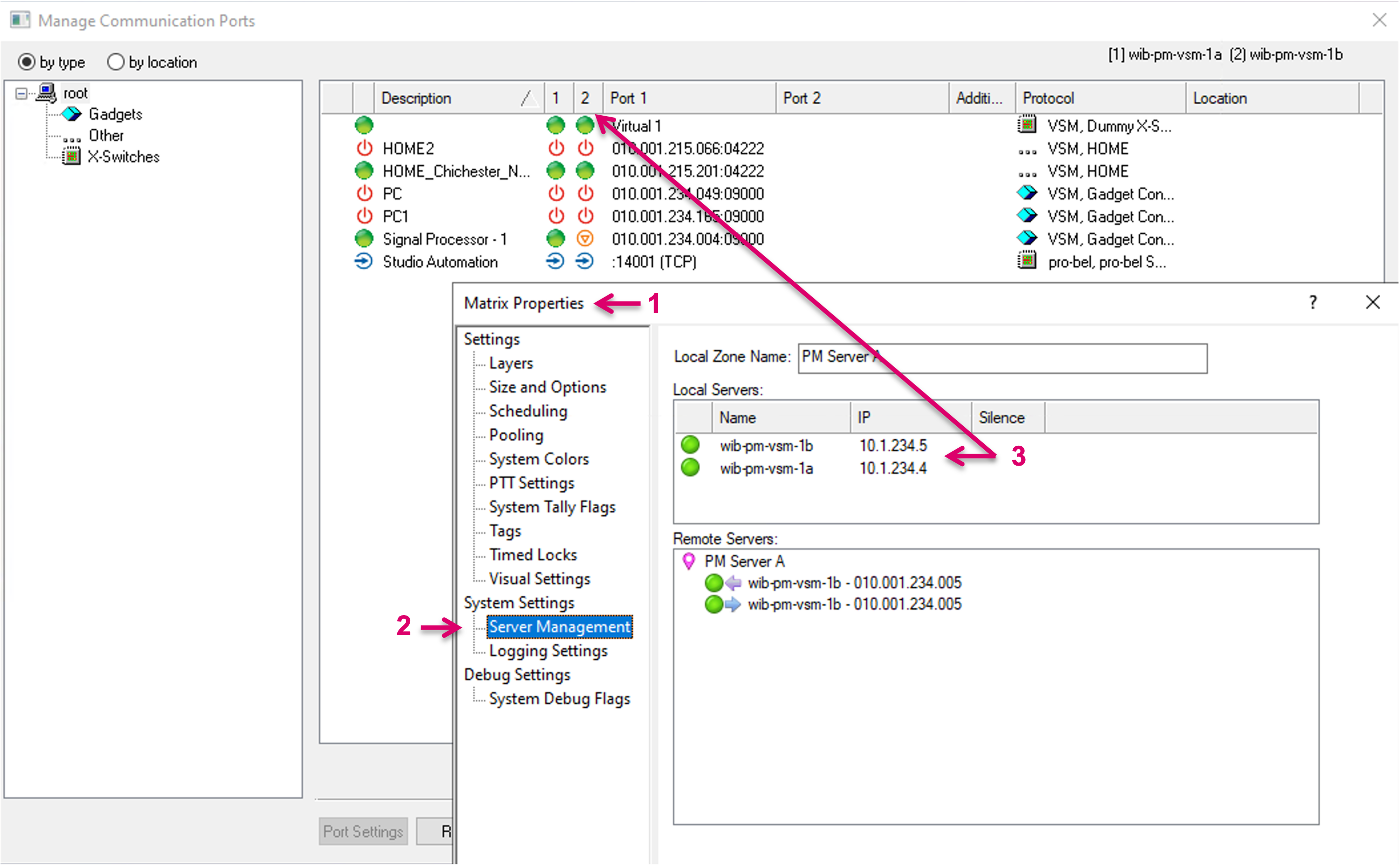
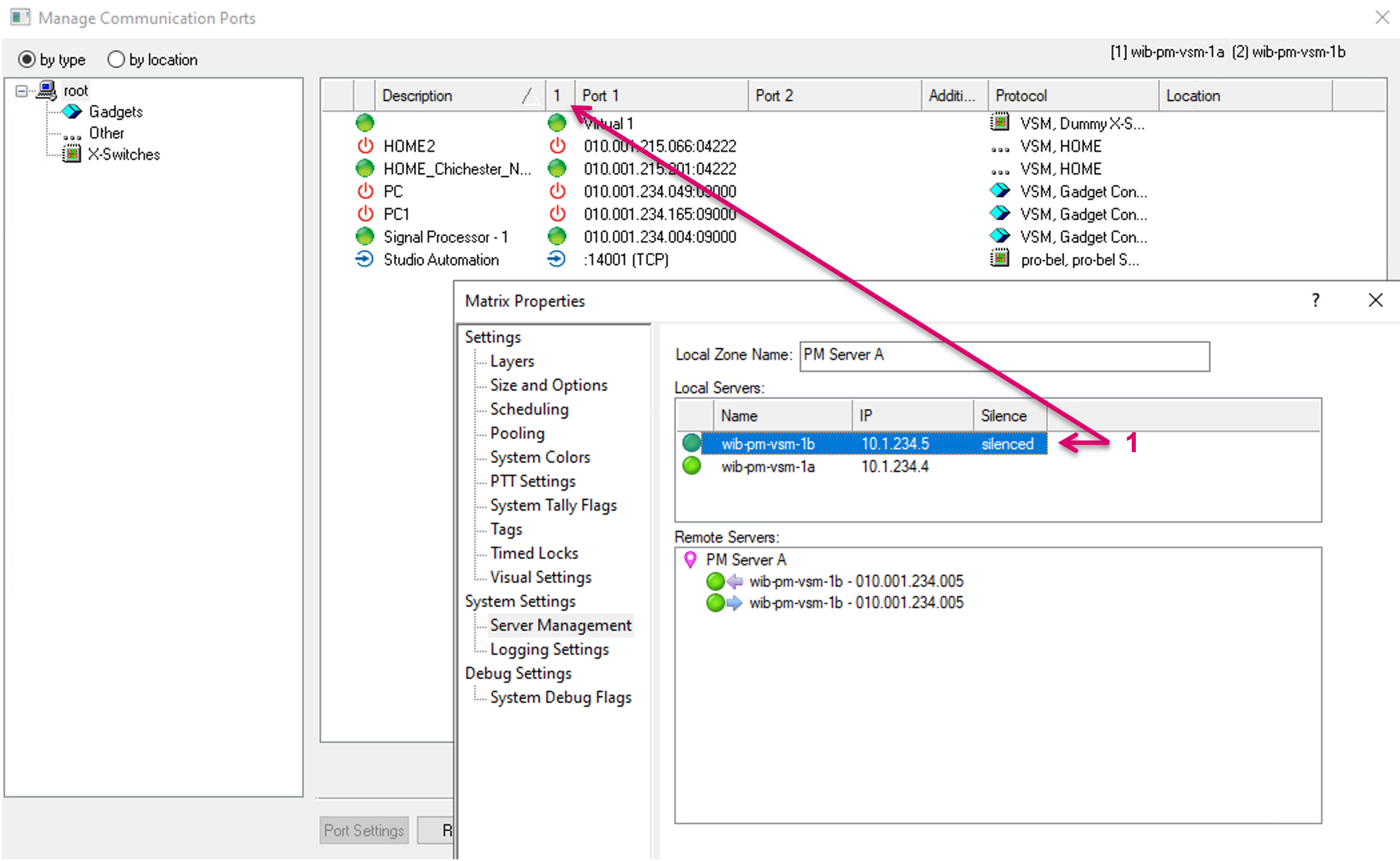
To hide or show a Server, open the Matrix Properties (1) and navigate to Server Management (2).
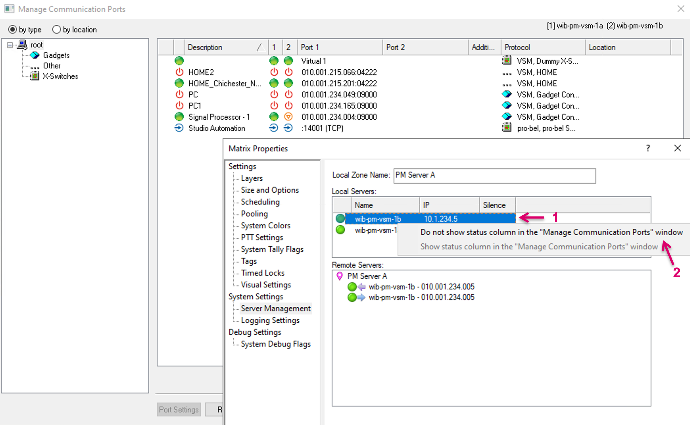
Right click on the corresponding entry in the list of local servers (1) and select Do not show status columns… (2).
The respective Server will be marked as silenced and the status column will not be displayed any longer in the Manage Communication Ports view (1).
Reset Communication Ports
Under some circumstances it may be required to reset a Communication port. This can be triggered in various ways.
To reset all Communication ports at once, go to the Manage Communication Ports view without selecting any specific Communication port. Click Reset at the bottom of the window (1) and you will be prompted to confirm this action in a pop-up window (2).
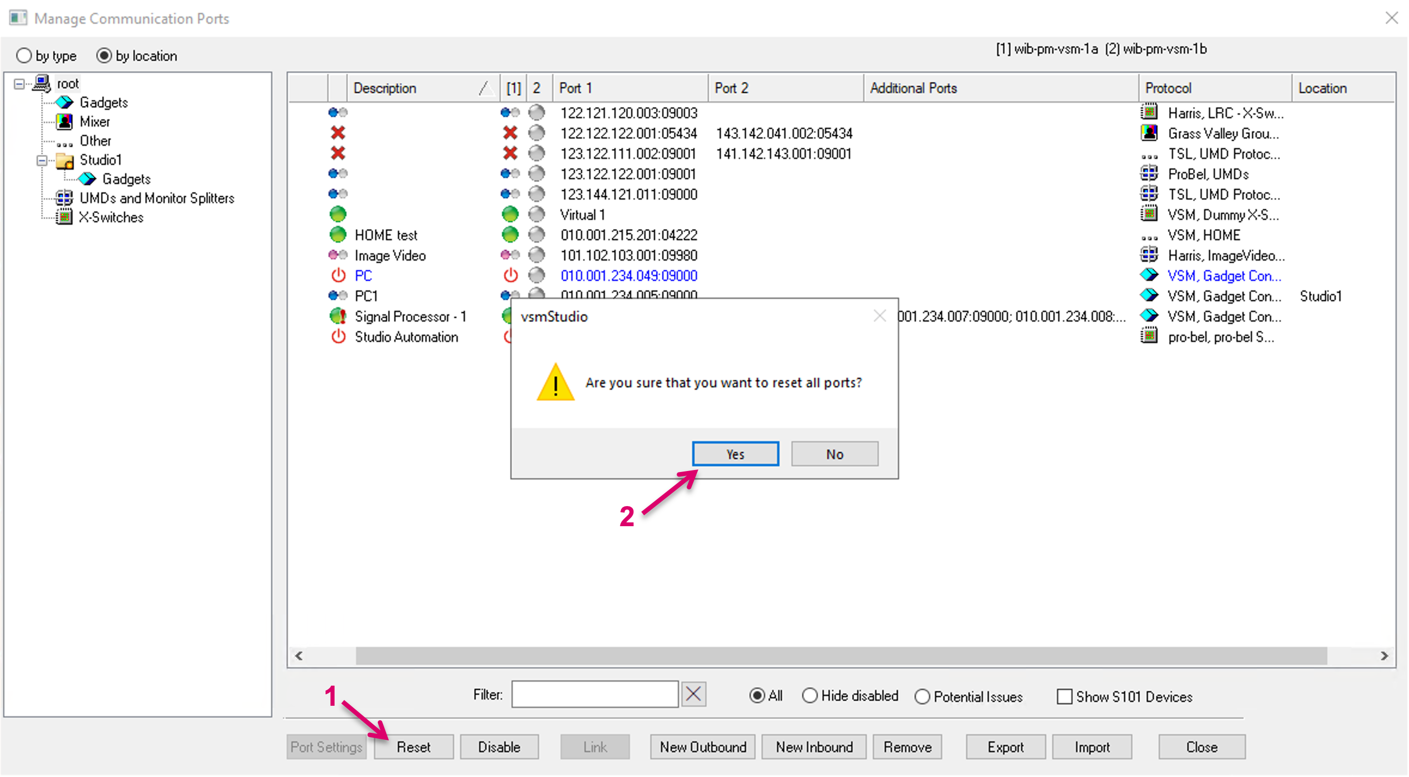
Resetting all ports at once is not recommended in live systems and usually not required. Aside the expected operational interrupt related to the respective ports, the overall system performance may also be affected, depending on the size of the system, chosen protocols or the type of connected devices.
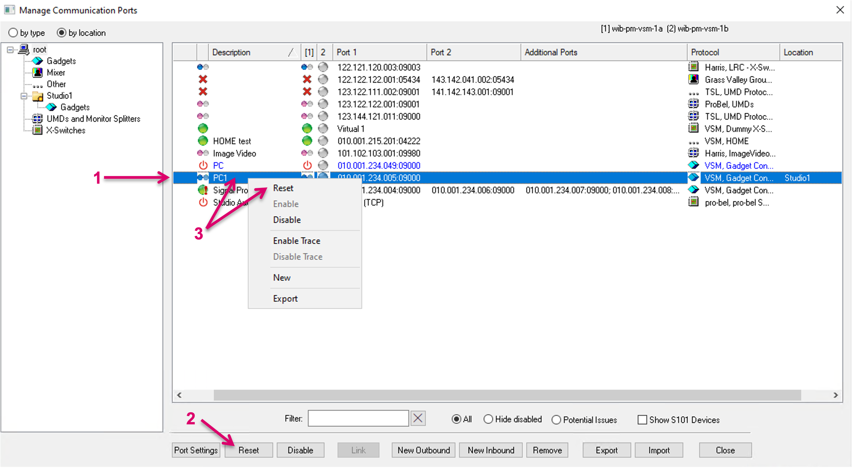
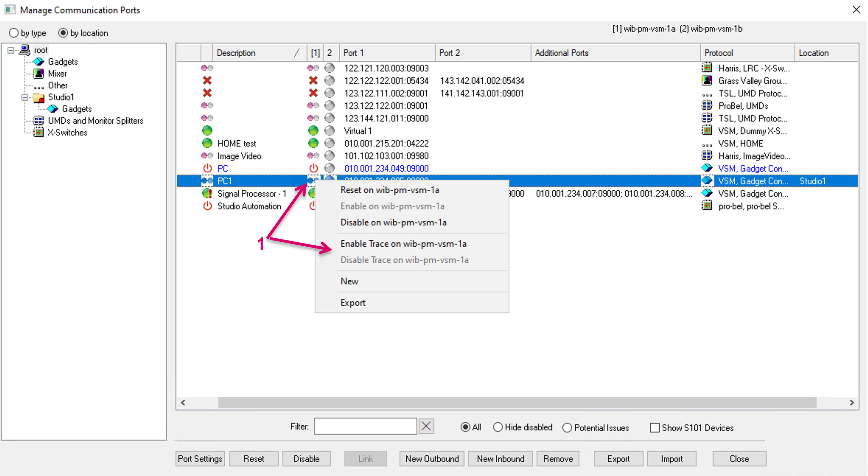
To reset specific Communication ports, select the respective Communication port(s) and click Reset at the bottom of the window (2). No additional confirmation is requested. It is also possible to right-click on any of the Communication ports and select Reset in the context menu (3).
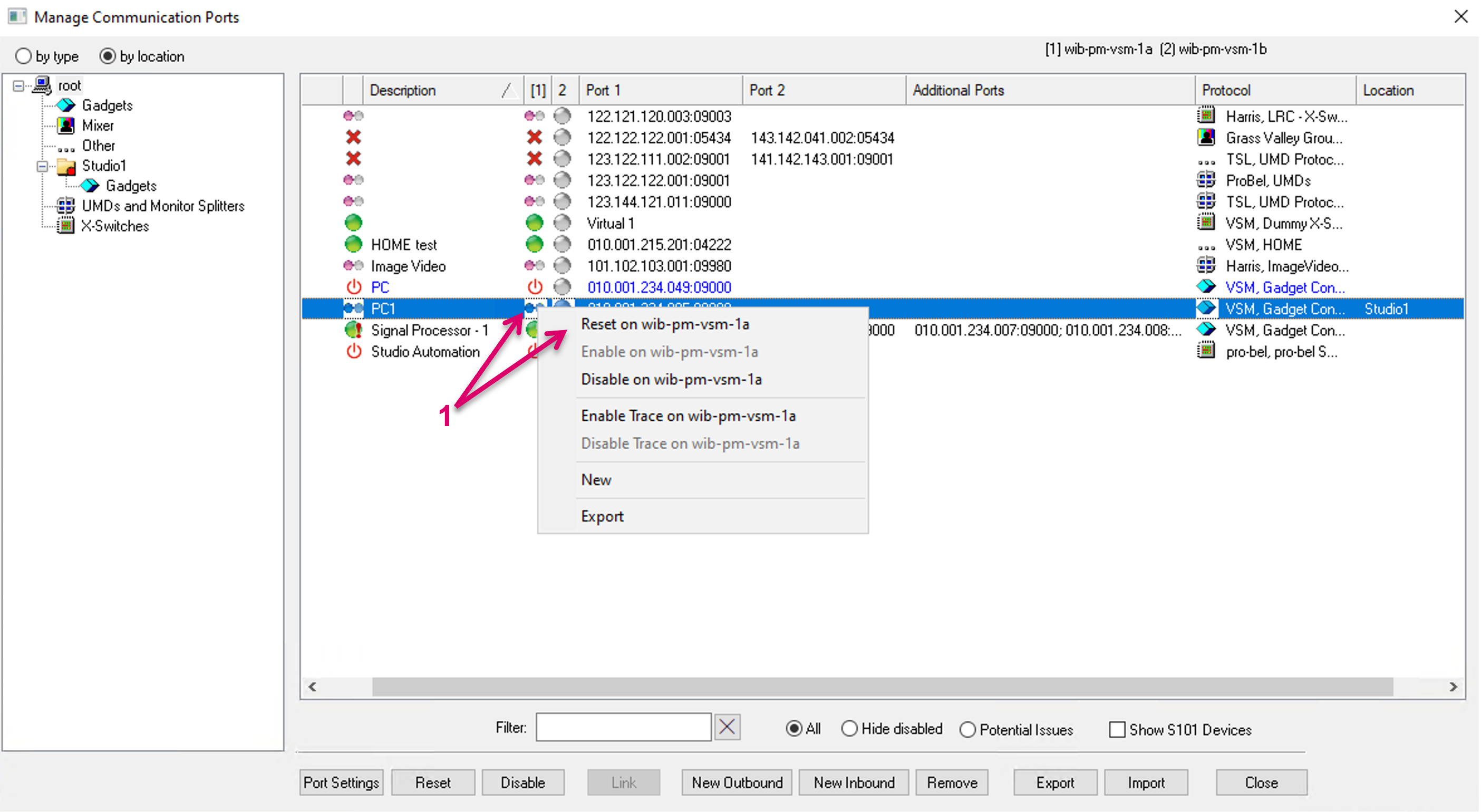
Another option to Reset is targeting the Reset of a Communication port connection from a specific Cluster Server. This can be triggered by selecting any Communication port entry, right-click on the Status indicator of a specific Server and select Reset in the context menu (1).
Location
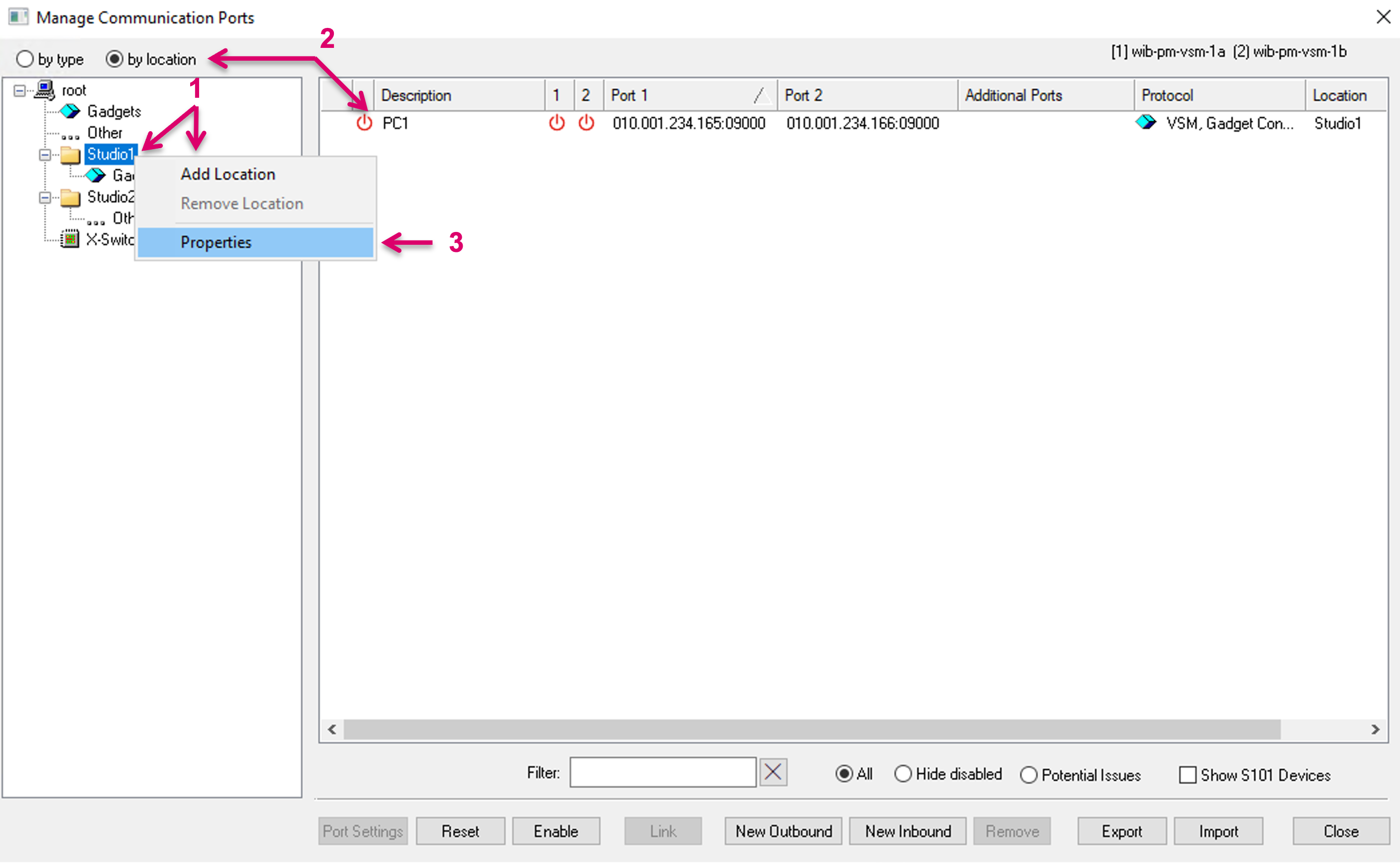
For a better organized view in the Manage Communication Ports window, it is possible to create user defined Locations (1). Communication Ports can be dragged and dropped into such Location folders and the view can be filtered by location (2). In the sub-menu of the Manage Communication Ports view, make a right-click and select Add Location (1). Open Properties (3) for additional settings.
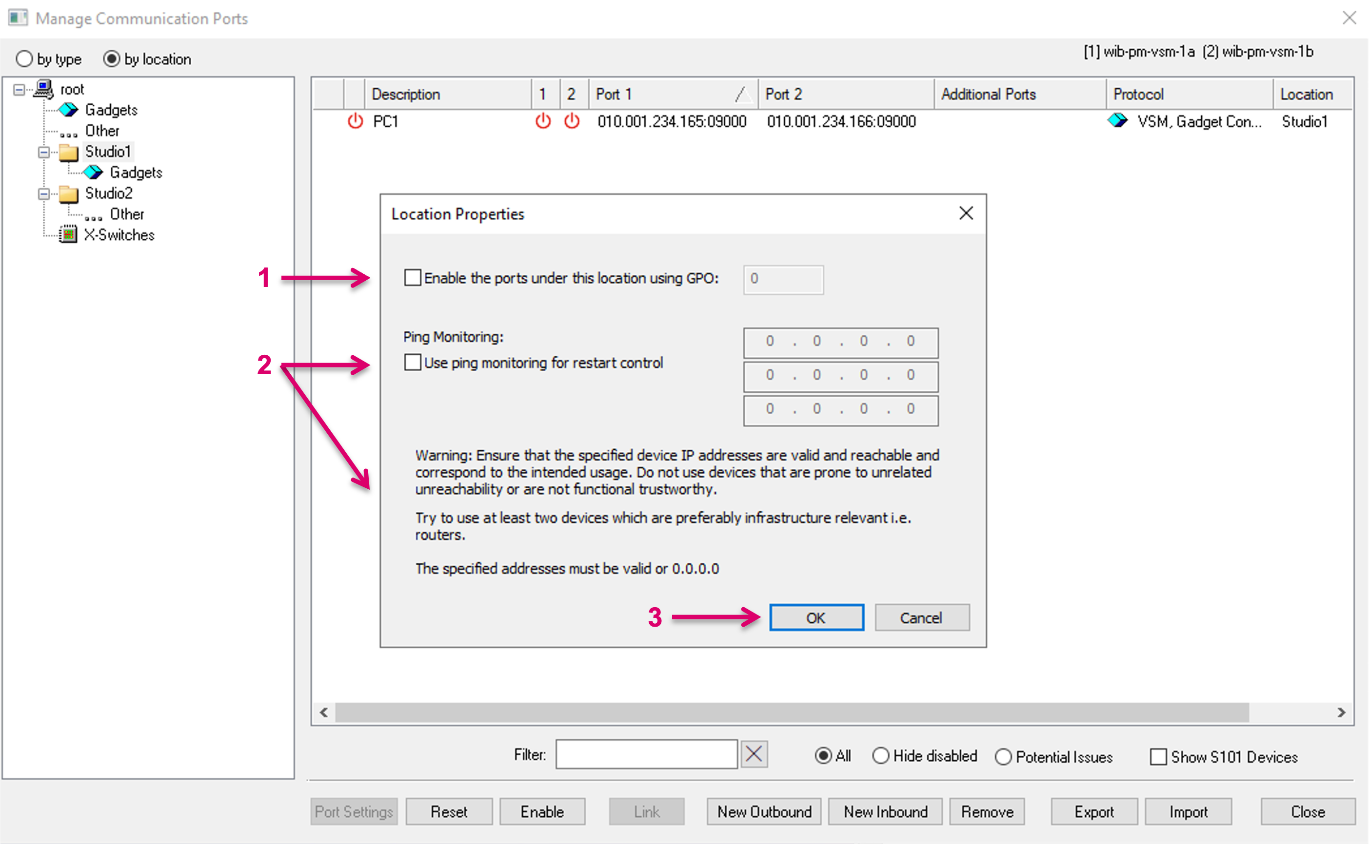
In the Properties view of a Location, it is possible to Enable all Ports assigned to this Location by a dedicated GPO (1). Ping Monitoring can be used for restart control (2). Please note the Warning text in the pop-up dialogue. Confirm settings with OK (3).
The location folder icons also show status information with following meaning: | |
| No Ping Monitoring is set. Normal folder icon. |
| Ping Monitoring is set. Location Properties settings modified. |
| Location folder contains connections with trace enabled. |
| Within the location folder, a connection is confirmed but there has been no communication in the last 15 seconds. |
| Within the location folder, a connection is established and pending. |
| Wonky = ping has drops. |
| Dead = ping without answer. |
Create a New Communication Port
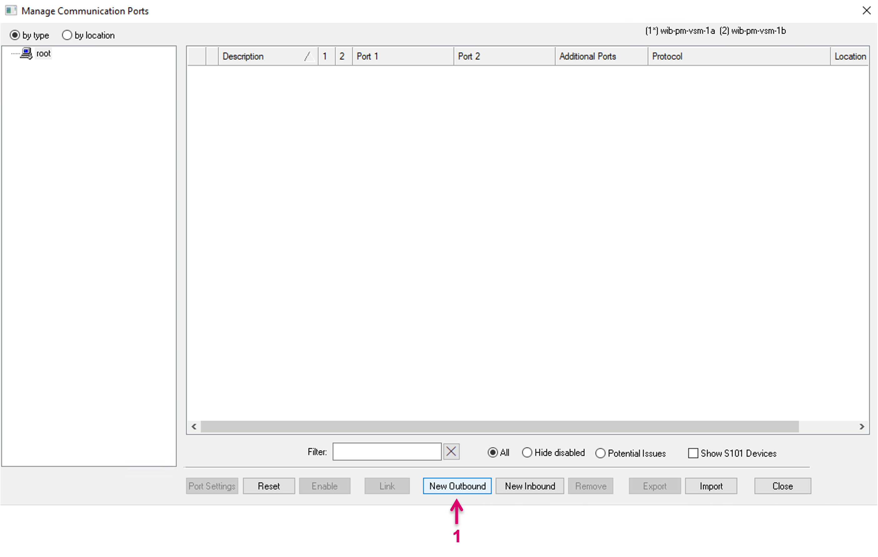
To configure a new Communication Port, select the respective button on the bottom of the window. Select the desired direction, Outbound or Inbound.
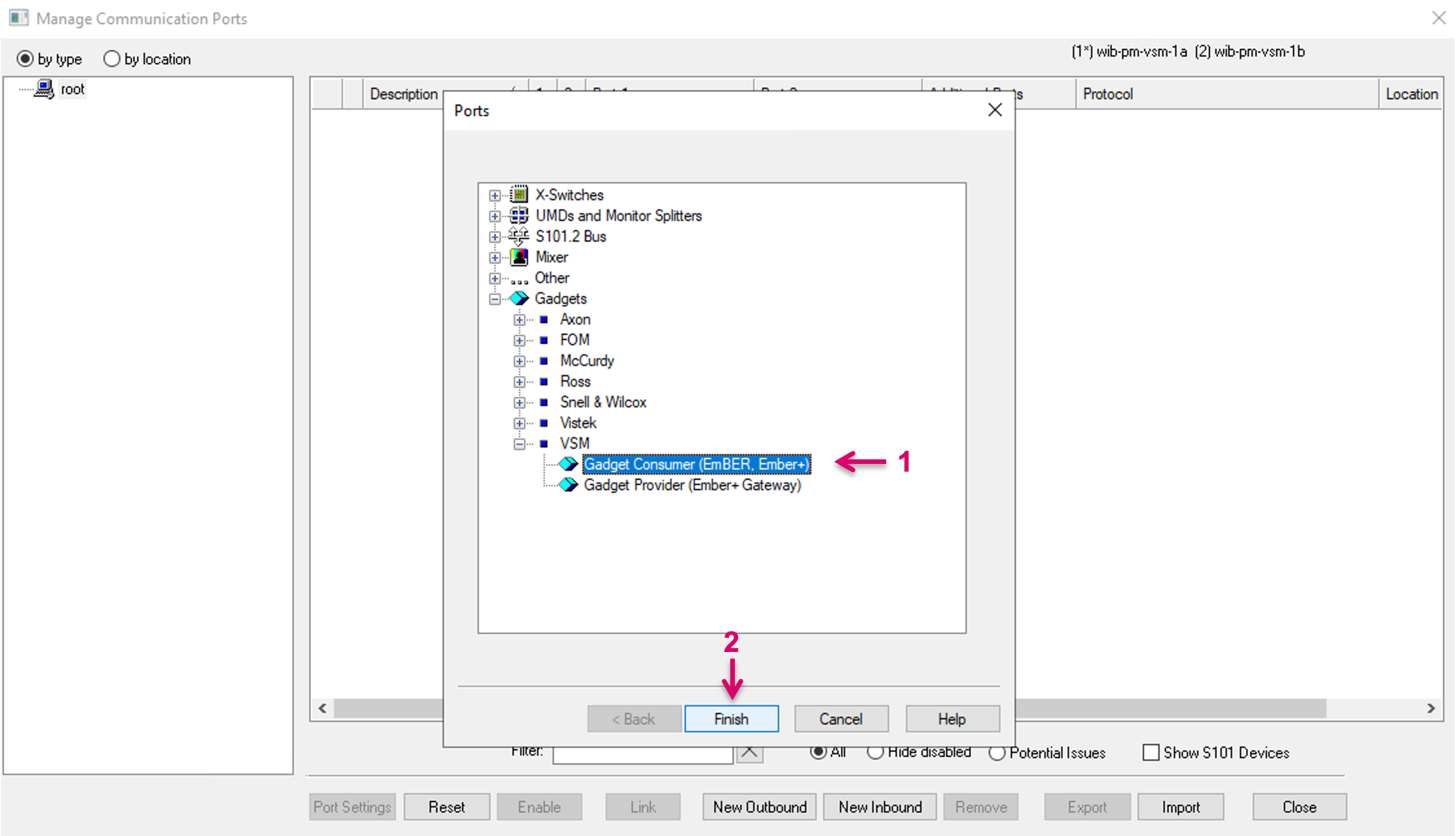
Select the respective device category (1),
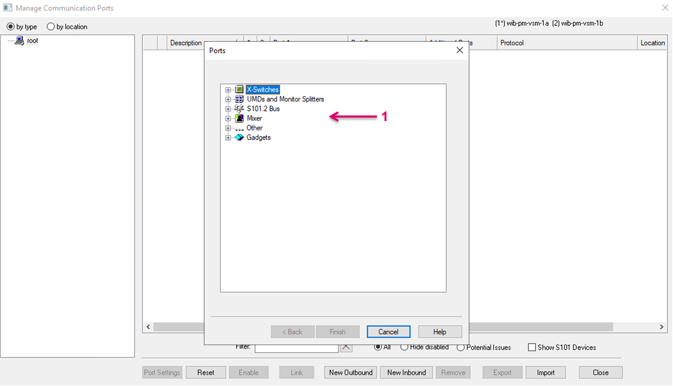
and Protocol (1). Please note: Supported for Inbound routing control are currently only Probel sw-p-08 and Quartz Native (Router Emulation) protocol. Continue with Finish (2).
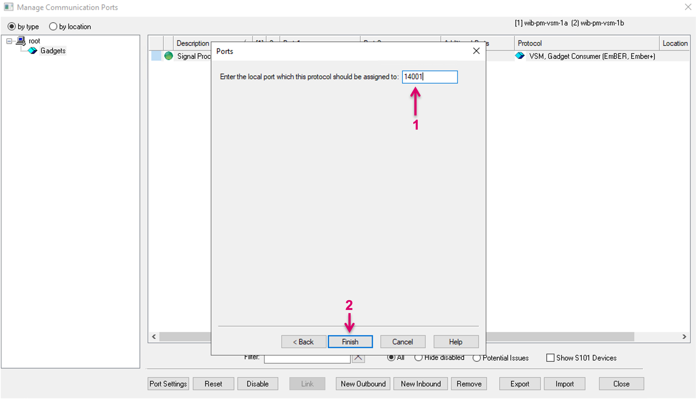
When creating an Inbound port, you will be prompted to set a communication port (1) before you can proceed via the Finish button (2) to further Port Settings.
Communication Port Settings main view and sub-menu
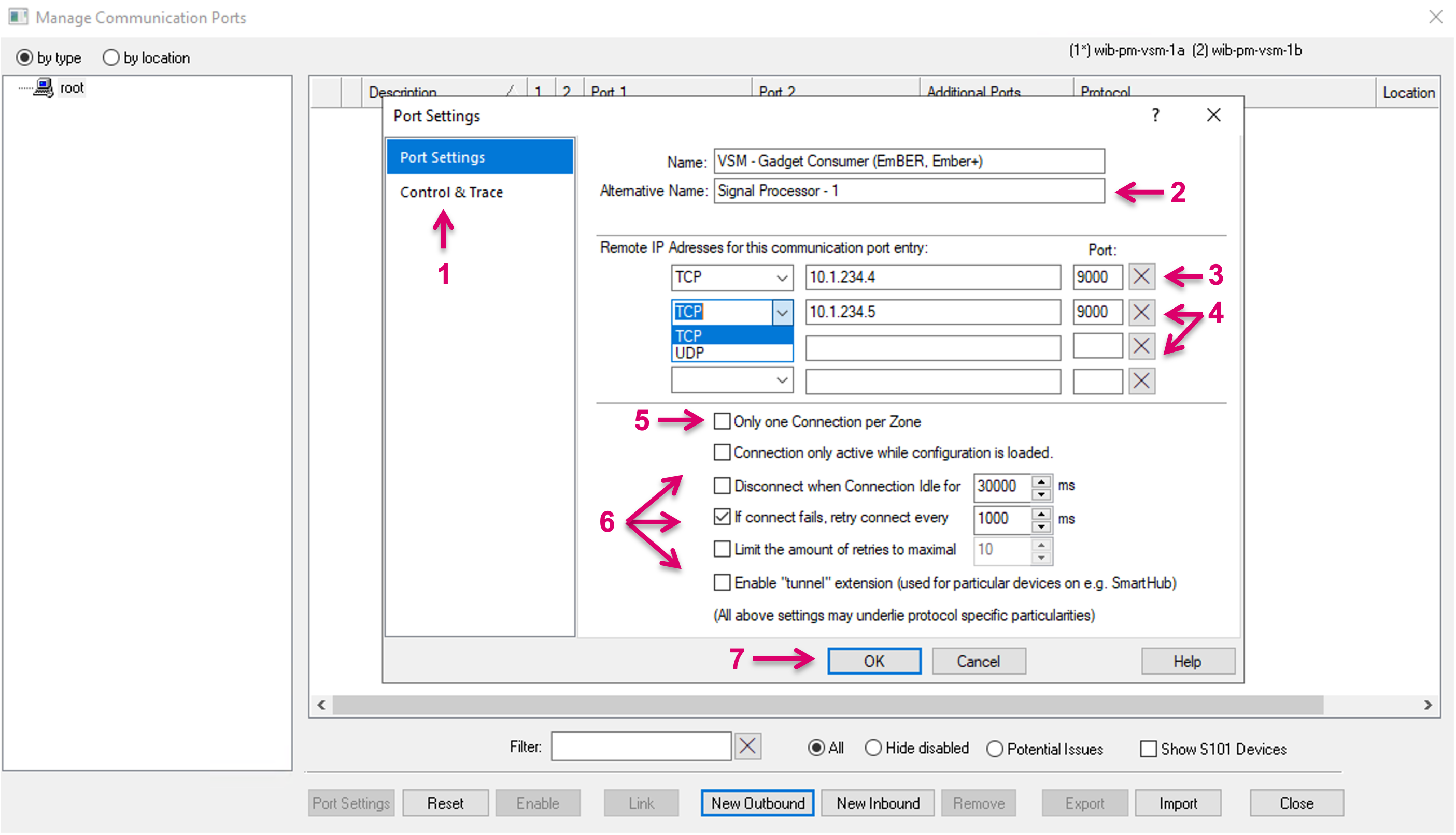
The opening dialogue gives access to the essential Port Settings. Please note, that the available entries in the sub-menu (1) and respective settings below, may vary, depending on the selected Protocol, as well as based on the fact if a configuration is loaded or not. A descriptive and unique Alternative Name (2) should be set to support the later administration of ports, where possibly many communication ports will show in one list. It is mandatory to set minimum one IP address and Port number (3). Choose if the communication will be TCP or UDP. For redundant device connections, enter two or more IP addresses (4).
Only one connection per Zone (5) is an option which exists to facilitate devices which have implementation issues in some way. It should only be used with devices which have problems with accepting multiple connections or have any implementation detail that prohibits clean multi connection control. Only one connection per zone ensures that only one vsmStudio Server will open a connection to this device and currently (subject to change in future), this will always be the current primary server. Since Only one connection per zone effectively limits the connection to one single server, the other servers cannot perform any redundancy traffic routing, in case the primary server, tagged as Only one connection per zone, is not able to connect to the device. Please also note that Gadget devices cannot be used with this mode.
Further available settings (6) address the connection handling, e.g., in case of connection loss or re-connects. These settings be only modified and used in special occasions and specific combinations of connected devices, used protocol, etc.
Finalize the Outbound Communication port setup by confirming with OK (7) or continue and proceed to any available sub-menu (1).
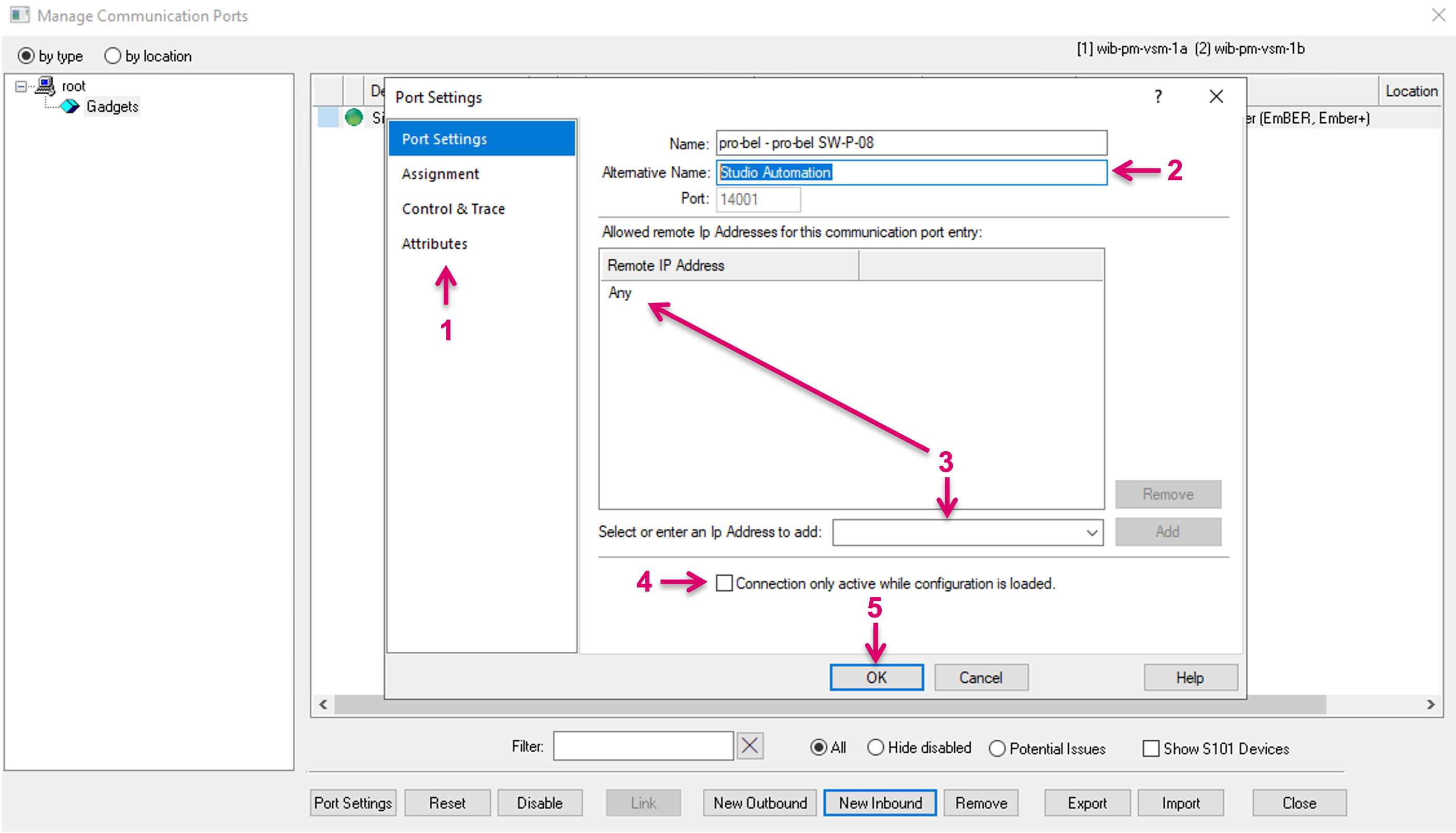
When creating an Inbound port, the main Port Settings view (1) may appear different. A descriptive and unique Alternative Name (2) should be set to support the later administration of ports, where possibly many communication ports will show in one list. For Inbound ports it is optional to define one or more IP addresses (3) to allow inbound communication. If not specified, any IP address can connect and communicate via the previously defined port. It can be set if the Connection should only be active while a configuration is loaded (4). Finalize the Inbound Communication port setup by confirming with OK (5) or continue and proceed to any available sub-menu (1).
Assignment
Depending on the chosen driver, routing- or label layer are supported and can be mapped in this dialogue.
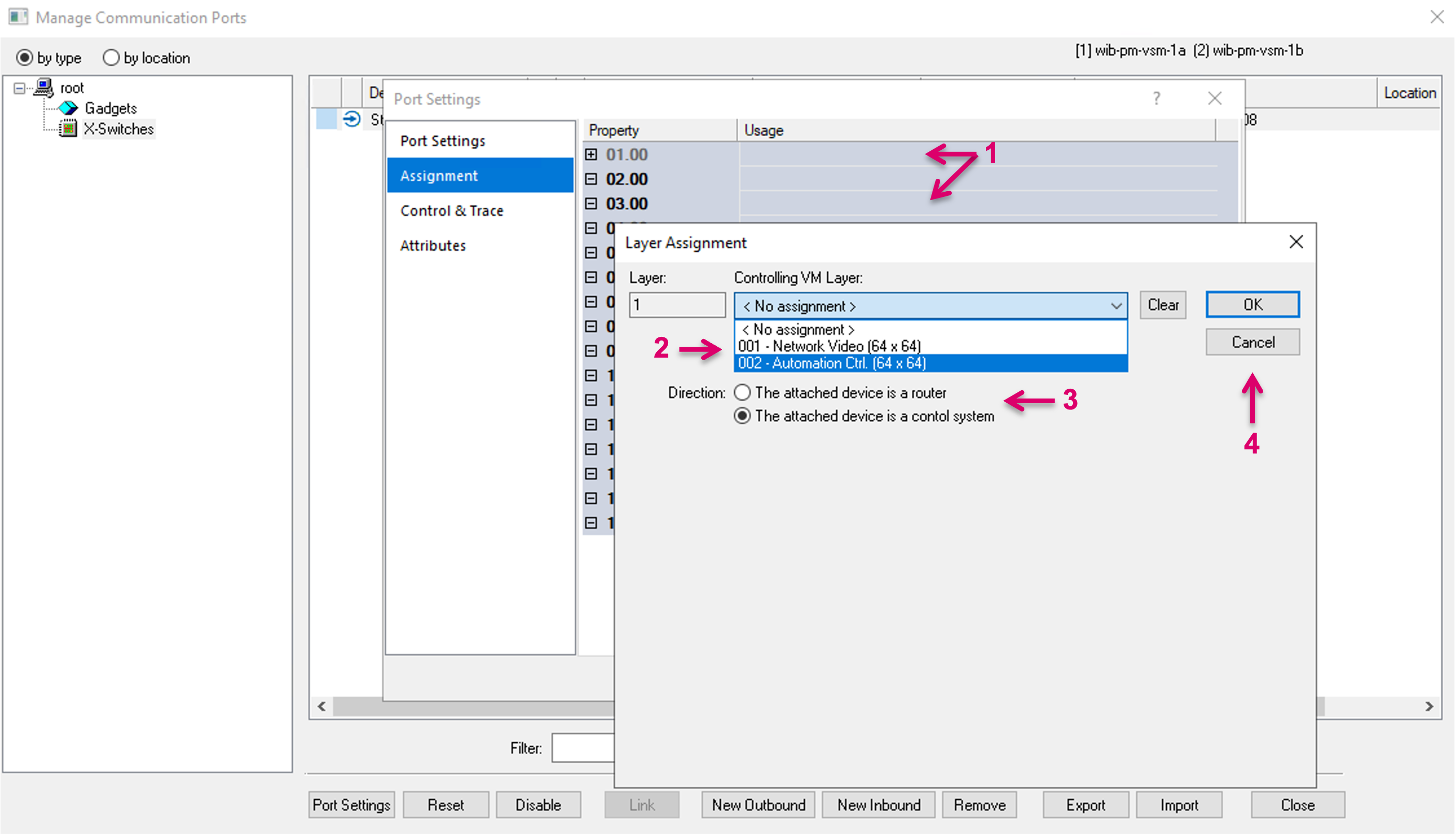
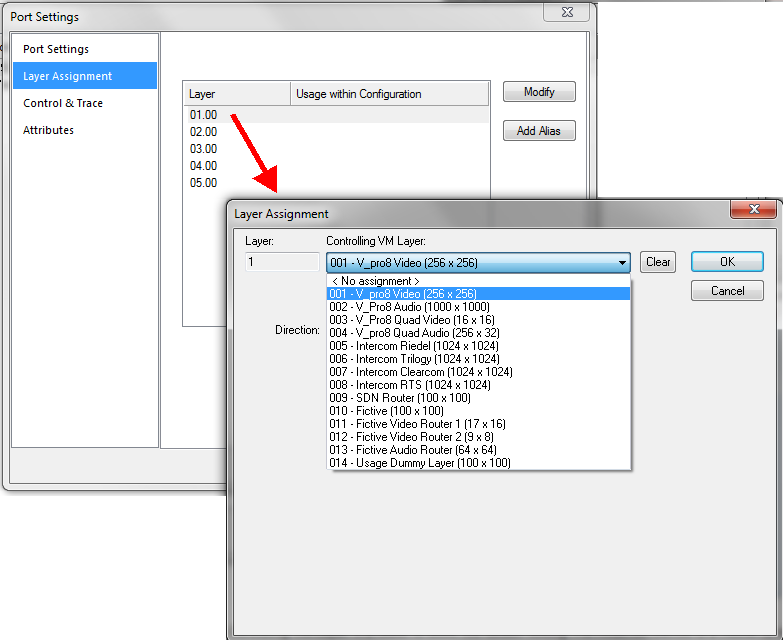
Layer Assignment
For a routing Layer Assignment double-click in the respective row (1). Then, in the pop-up window, select the vsmStudio Layer that shall be mapped (2). Select if the attached device is a router or a control system (3). The latter is usually the case on Inbound connections, e.g., a Studio Automation system that is supposed to set routes on a vsmStudio Virtual Layer. Confirm with OK or Cancel (4).
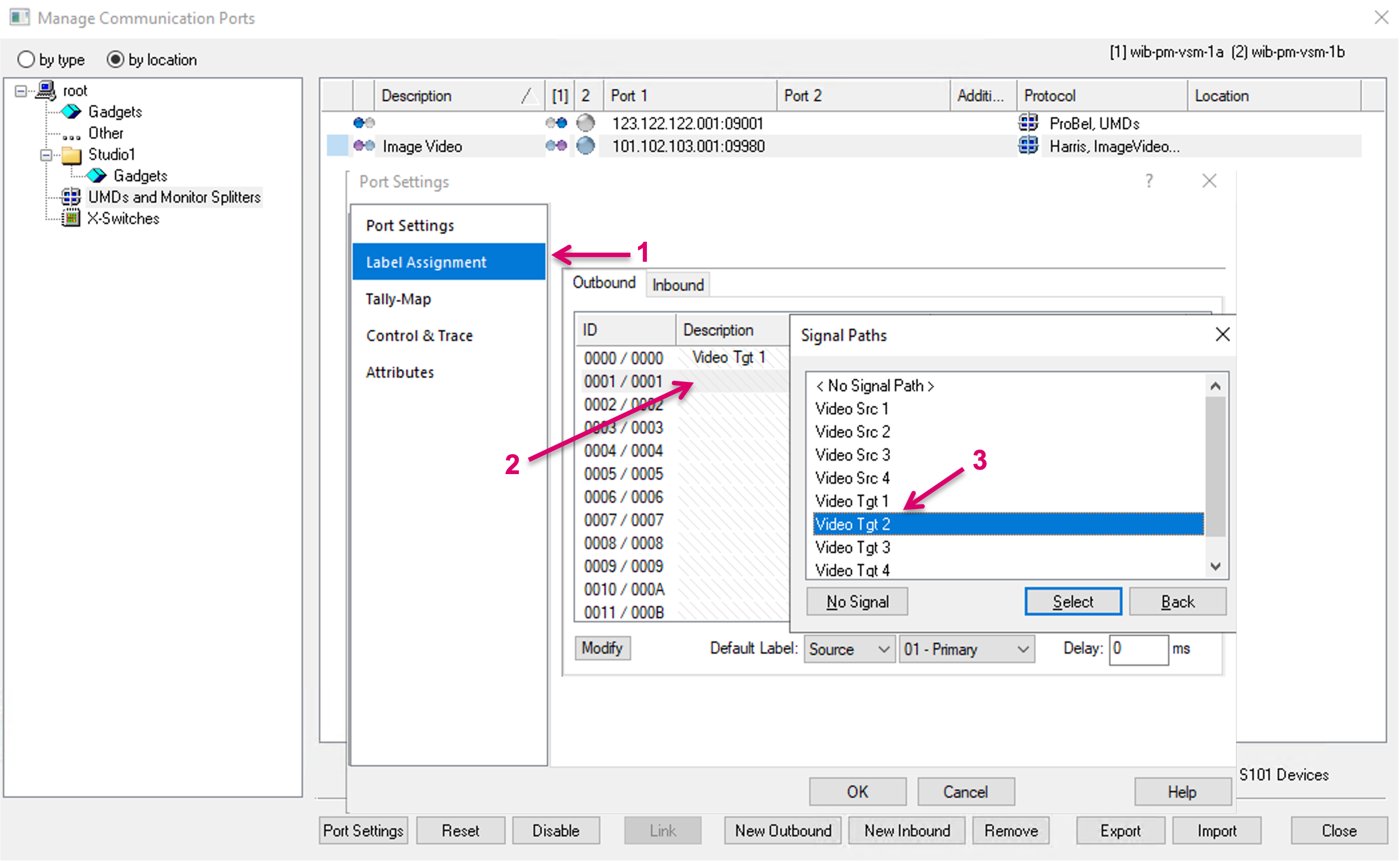
Label Assignment
Some Protocols allow for a label mapping. Select the Label Assignment in the sub-menu (1), select Outbound or Inbound direction via the respective tabs, then double-click in the desired row (2). In the opening pop-up window, select the vsmStudio Signal Path (3), whose label information shall be sent, by double click or via the Select button on the bottom. Please note, that Signal Paths must be located on the Primary Virtual Matrix to appear in the drop-down list. It is also possible to drag and drop one or multiple Signal Paths from Matrix view or Signal Path list. To delete an assignment, select No Signal.
By double-click in the Alternate Label cell (1) of an entry, it is possible to define a specific label layer (2), of the respective Signal Path, to be transferred. Default settings can be defined at the bottom of the window (3).
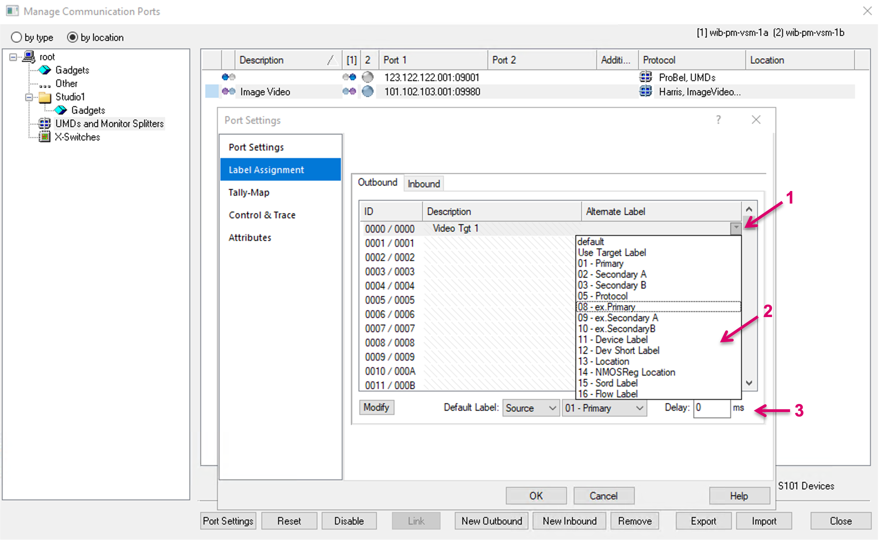
Please note that the respective mapping dialogues may vary, depending on the selected protocol.
Tally Map
Some Protocols allow for a Tally mapping. Select Tally-Map in the sub-menu (1), then set Tally Mask and Mapping per System Tally Color.
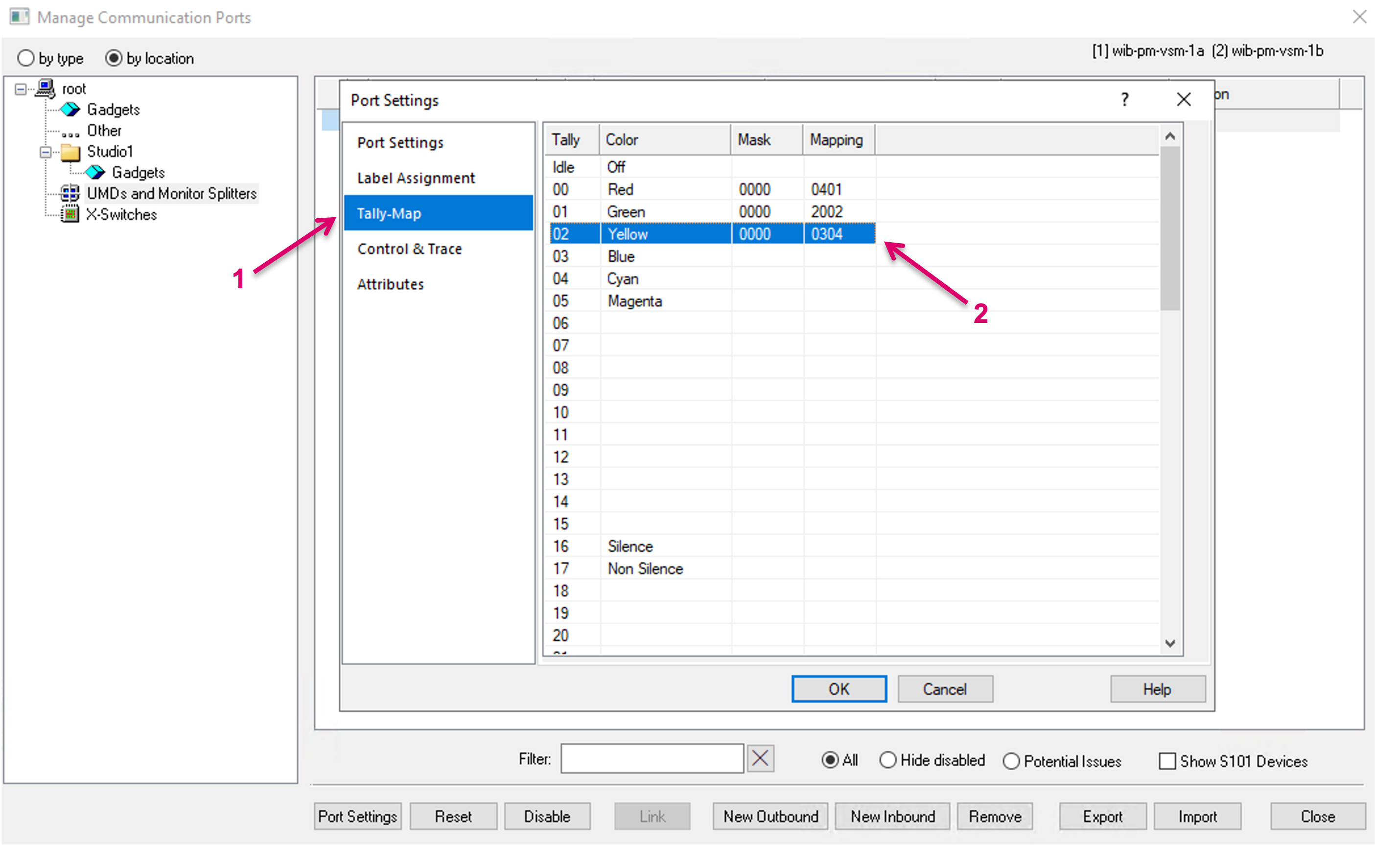
Please note that the respective mapping dialogue may vary, depending on the selected protocol.
Tally Settings
Some Video Switcher (Mixer) protocols come with specific configuration views (1) for mapping of Tally to vsmStudio GPI range and, if applicable, routing layer mapping (2). To set a GPI range, the starting GPI number must be defined. GPI areas must not overlap.
Specific Protocol Notes
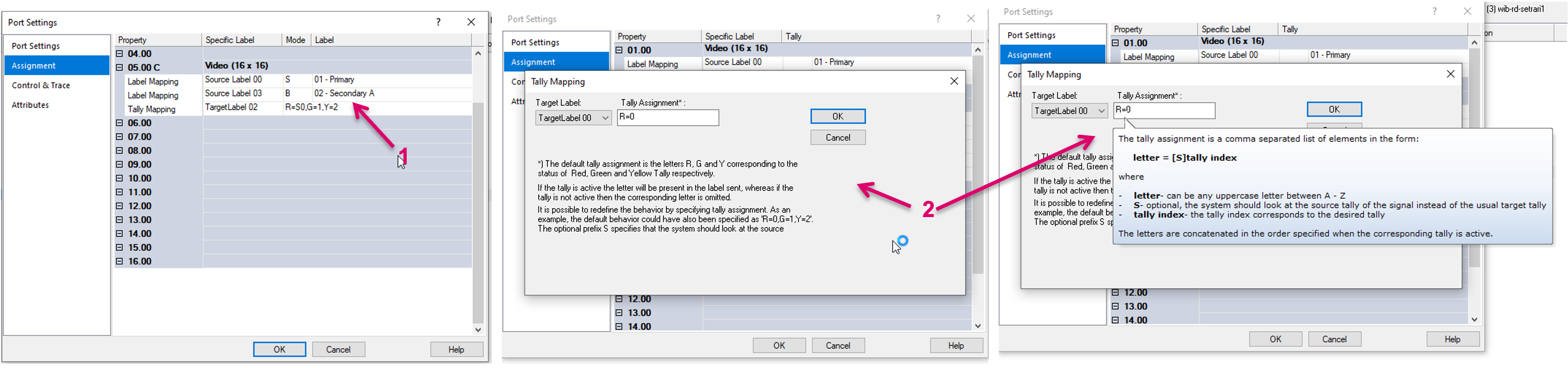
Some protocol implementations come with a different approach for the management of all available options and settings. For example, Probel sw-P-08, where the routing layer mapping is closely linked with optional Label and Tally mapping. For this protocol, all mappings are located under the Assignment sub-menu. Aside the layer mapping, a right-click in a layer row, specific label mappings can be defined using context menu options: Add Source Label, Add Target Label and Add Tally Mapping (1). Each option provides own additional settings (2).
Control & Trace
Settings in the Control & Trace section (1):
The option Enable this port using GPO, allows to enter a GPO ID, to enable or disable this port based on the GPO condition. Enter the desired GPO number into the respective field (2). Signal Operational Status using GPI allows to monitor a port via a GPI. Enter the desired GPI number into the respective field (3). The Enable Trace option activates the trace mode for this port (4). After checking this option, additional information is provided in CommTrace.
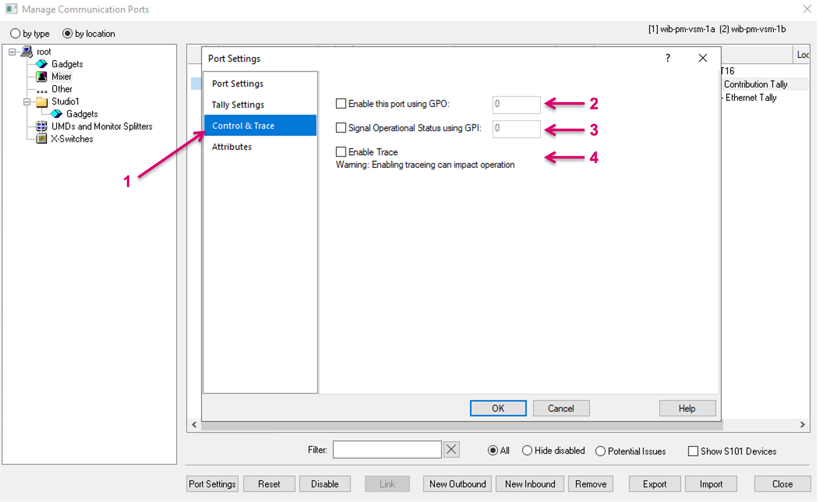
GPIOs must be configured manually in the dedicated GPIO configuration window.
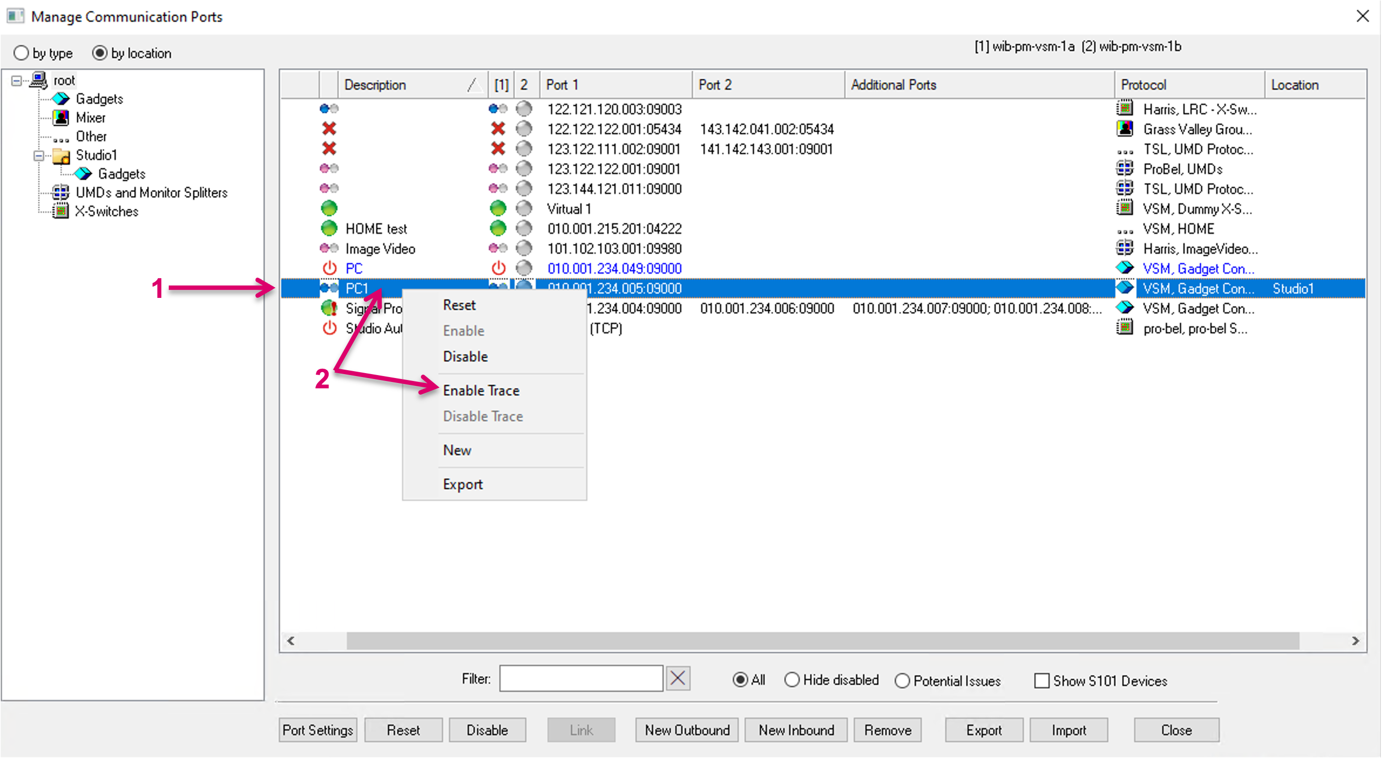
An alternative approach to enable Trace is directly in the port list. Right-click on any port (1) and select Enable Trace (2).
Another option allows to enable Trace for a port in context of a specific Cluster Server. This can be triggered by selecting any Communication port entry, right-click on the Status indicator of a specific Server and select Enable Trace in the context menu (1).
If Trace is enabled, the respective port is displayed in blue font to indicate that tracing is still active (1).
Enabling tracing can impact operation and affect the performance of your system.
Attributes
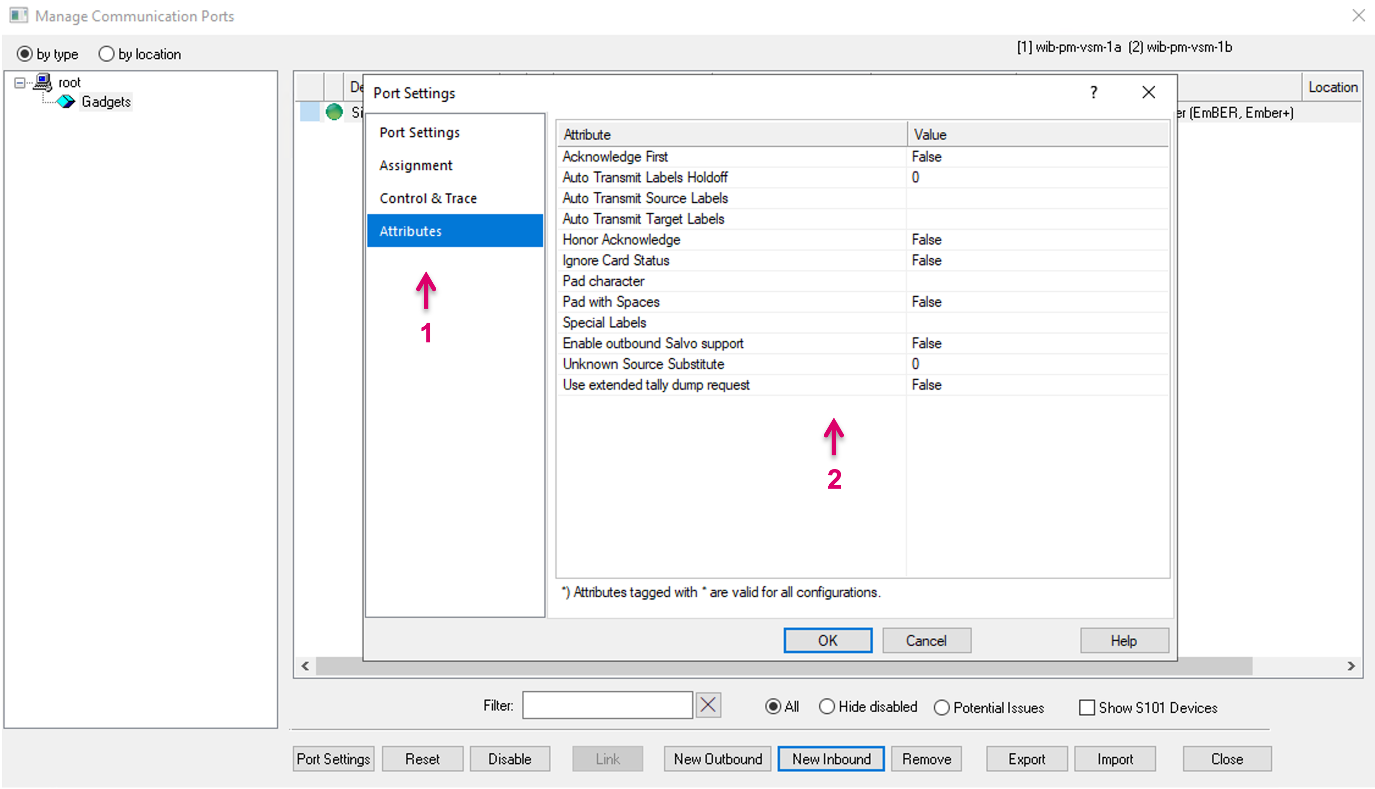
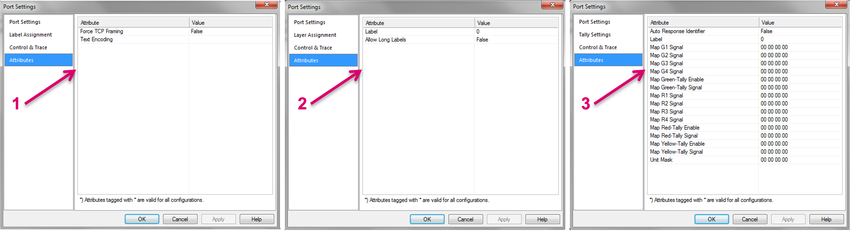
Available attributes in this section (1) may vary based on the selected protocol (2).
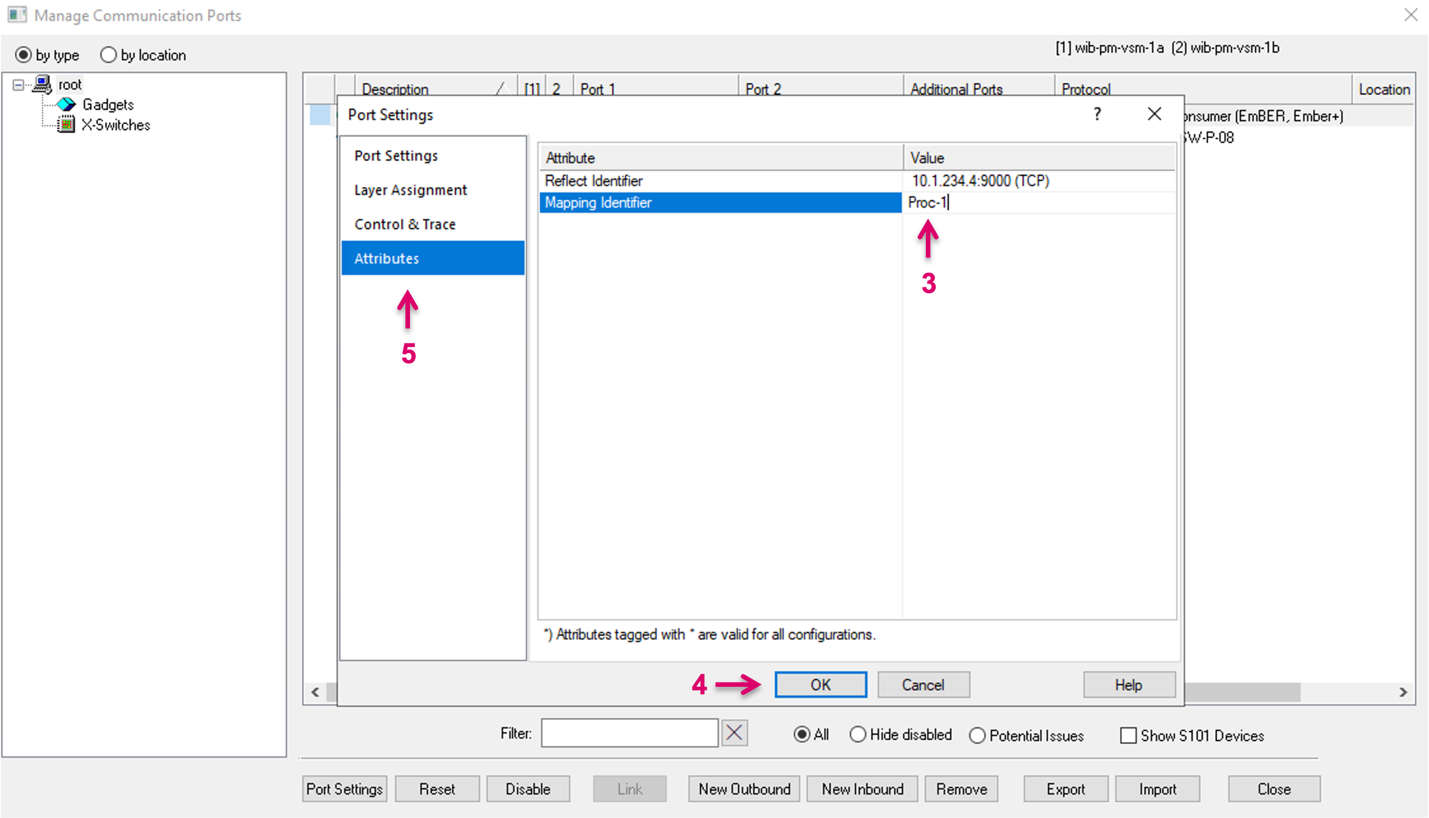
For Ember+ Ports it is strongly recommended to always set a Reflect Identifier (3). The Reflect Identifier is essential for the system to trace a resource back to the top node. If the Reflect Identifier changes, after a resource was already used in configuration, the path is broken, and the resource will appear offline. By default, the system will use the IP address as the Identifier. In case the device IP must be changed later, or the used parameters shall be used with a different device (of same type) at any time, it is strongly recommended to use a unique and descriptive name, instead of a specific IP address from the start. Same principle also applies for the Mapping Identifier. To finish this configuration step continue with OK (4) or continue in another sub-menu (5).
Other Attributes view examples. UMD (1), Router (2) and Switcher (3).
Ember+
One of the currently most relevant protocol interfaces is Ember+.
A multitude of protocol drivers are implemented in vsmGadgetServer and cannot be selected directly in vsmStudio. In this case, vsmGadgetServer will provide the interface between end-device and vsmStudio. The communication protocol between vsmGadgetServer and vsmStudio is Ember+.
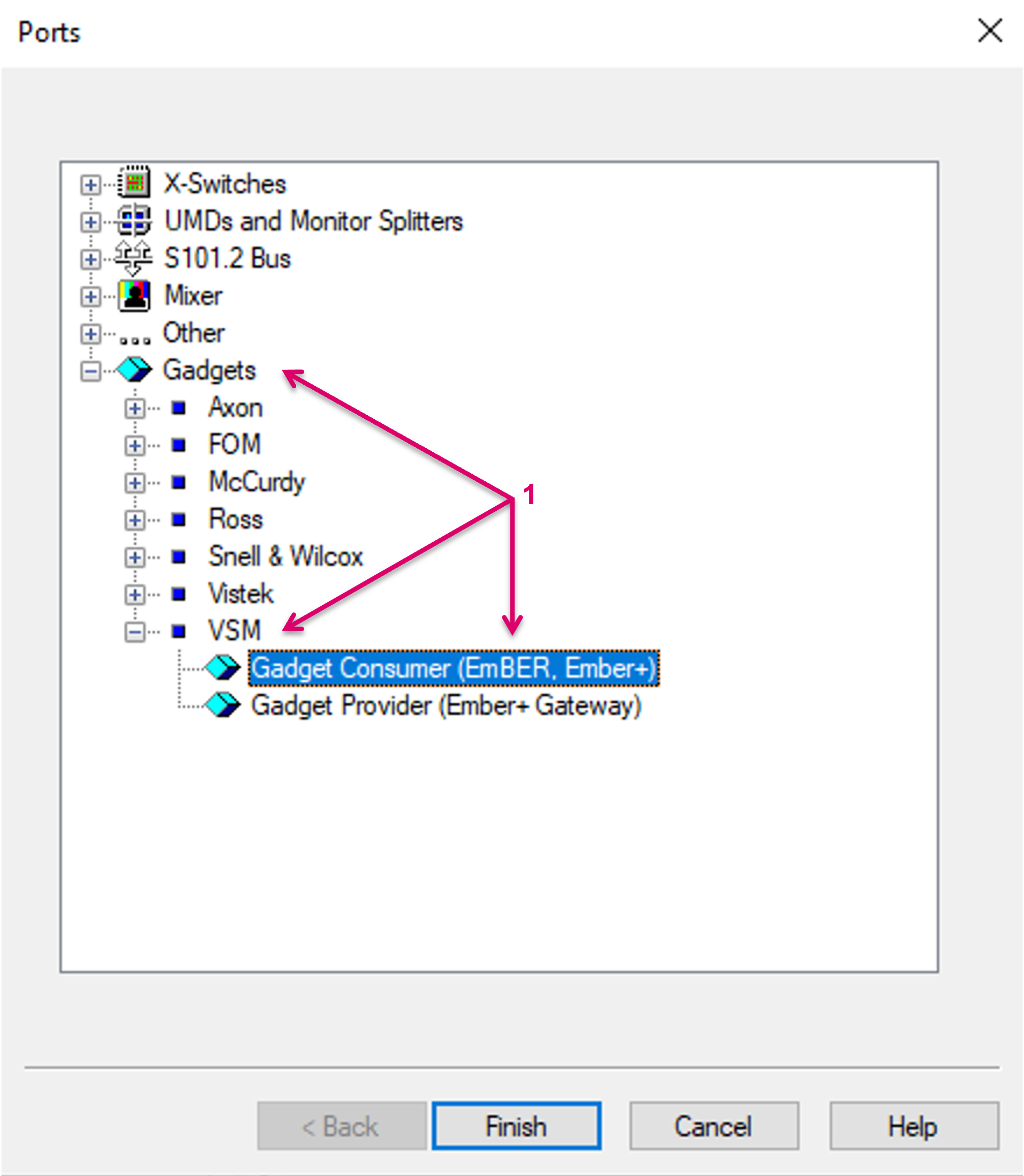
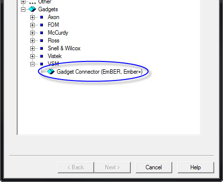
Furthermore, Ember+ is widely adopted and supported directly by many vendors and third-party devices. Within the driver list Ember+ can be found here: Gadgets/VSM/Gadget Connector (Ember, Ember+) (1).
HOME API and NATS Leafnode Server
Another major important protocol is the Lawo HOME API interface. The HOME API allows the direct connection to Lawo’s HOME platform. This constantly enhanced interface gives access to all registered devices and resources within the HOME platform and allows for simplified resource configurations. Once the connection to a HOME Server cluster is successfully established, all devices, that are registered in HOME will be listed in the HOME dialogue and Signal/Stream resources can be easily configured from there. In addition, the Gadget tree will provide a HOME node, providing access to all parameter (GCF) controls of registered devices.
While it was and is possible to connect to each physical HOME Server directly, this is not the most efficient way to interface. Therefore, with vsmStudio release 26.1.1, we introduced a new method to interface to a HOME cluster, via a local NATS Leafnode Server, that runs on each vsmStudio Cluster Server. The connection is then established via one single connection between vsmStudio and the local NATS Leafnode while the NATS Leafnode Server itself connects to and communicates as part of the HOME cluster.
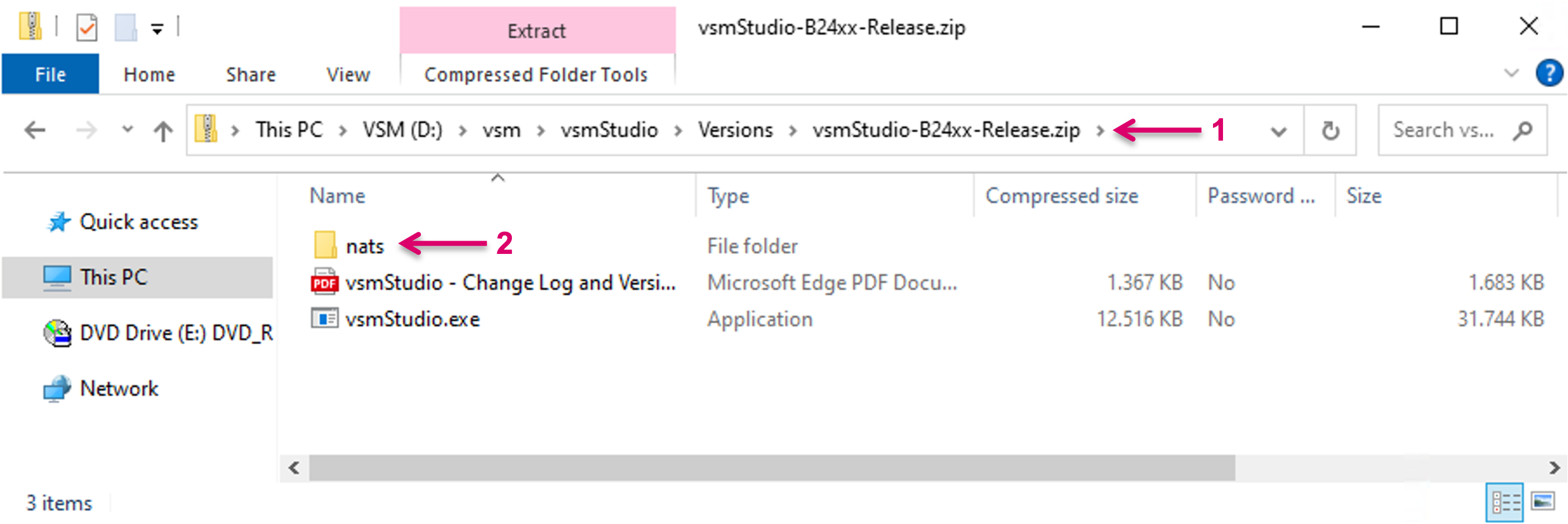
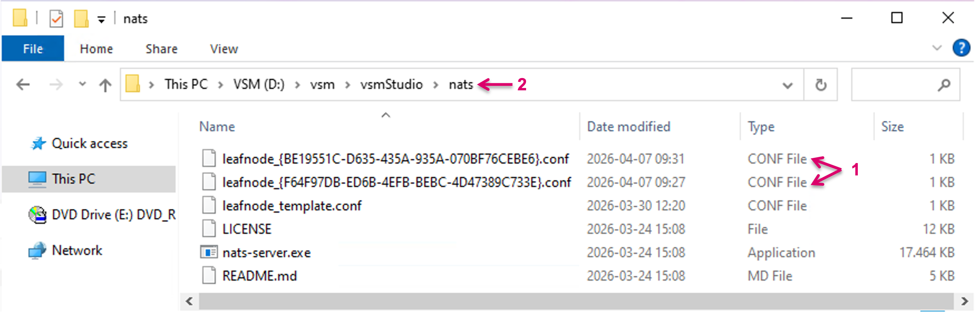
The NATS Leafnode Server is provided as part of the vsmStudio release package\.zip (1), located in the folder "nats" (2). It is mandatory to copy this entire nats folder together with the vsmStudio exe into the same directory folder on the vsmStudio Server. This must be done, the same way on each Cluster Server.
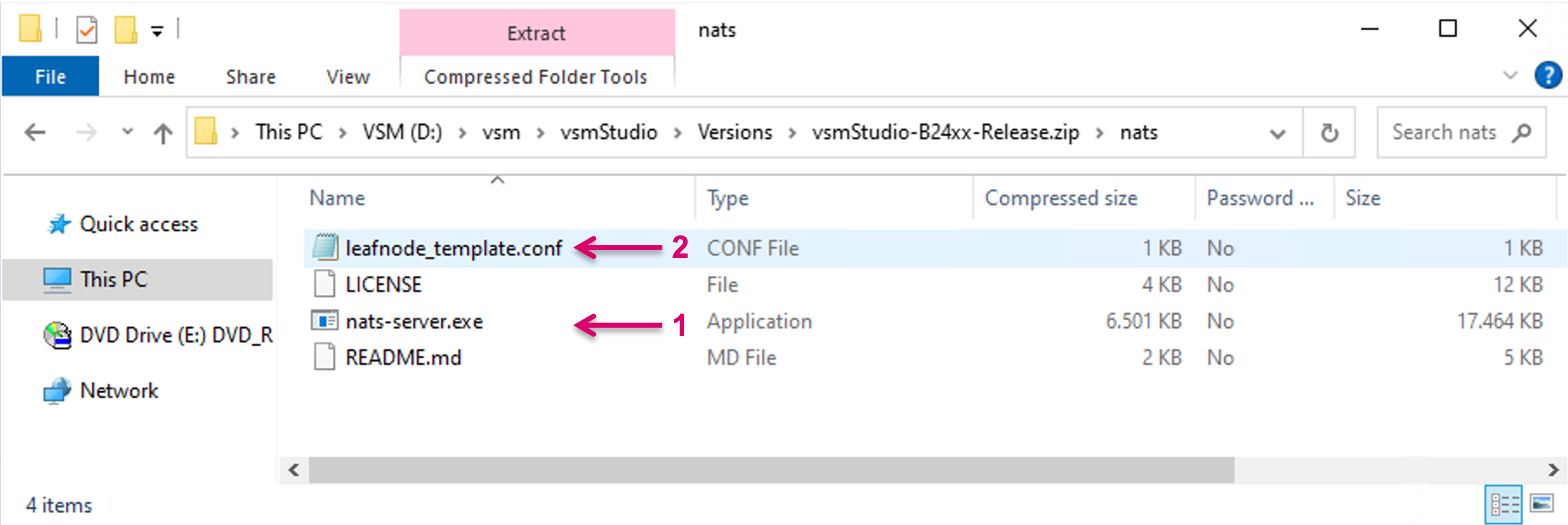
The nats folder contains the process nats-server.exe (1) as well a template configuration file (2) which is mandatory for the system to create configuration related files later.
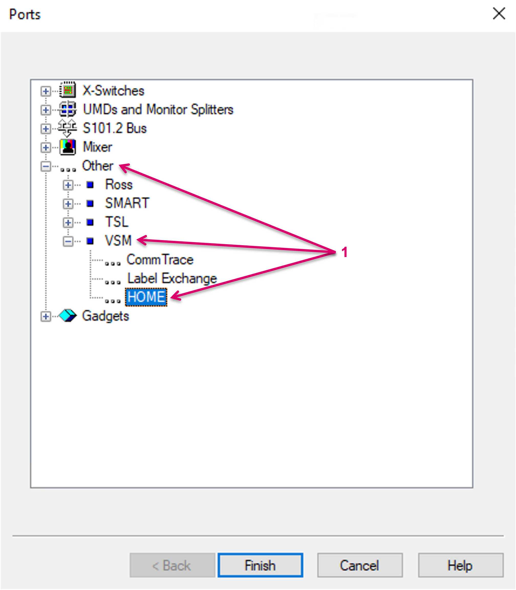
The configuration of the communication port for the HOME connection does not differ much from any other port. Within the driver list of the Ports view, the HOME API can be found here: Other/VSM/HOME (1).
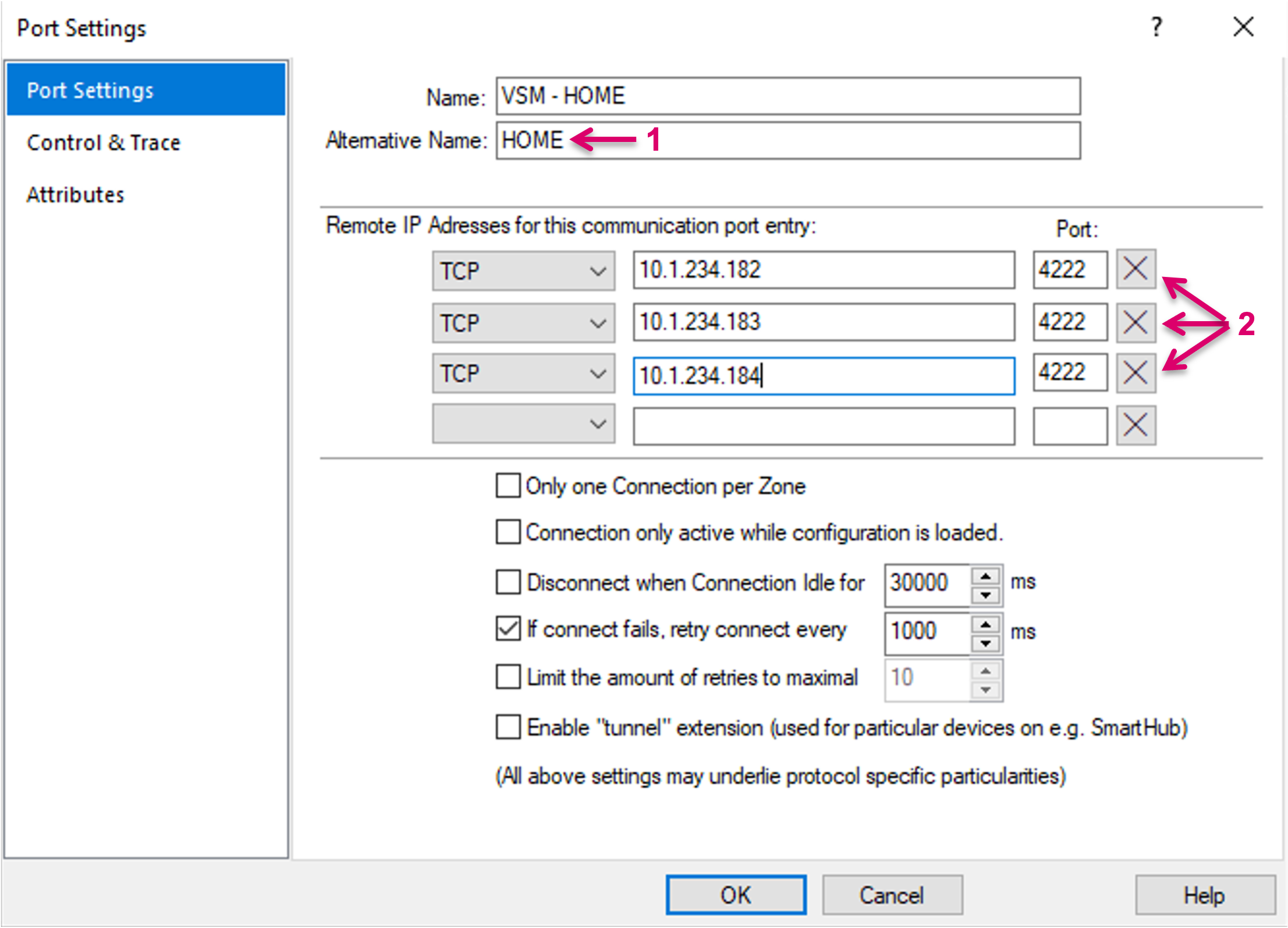
In the port settings a Name can be set (1) and here you enter the direct IP addresses of all HOME Cluster Servers (2).
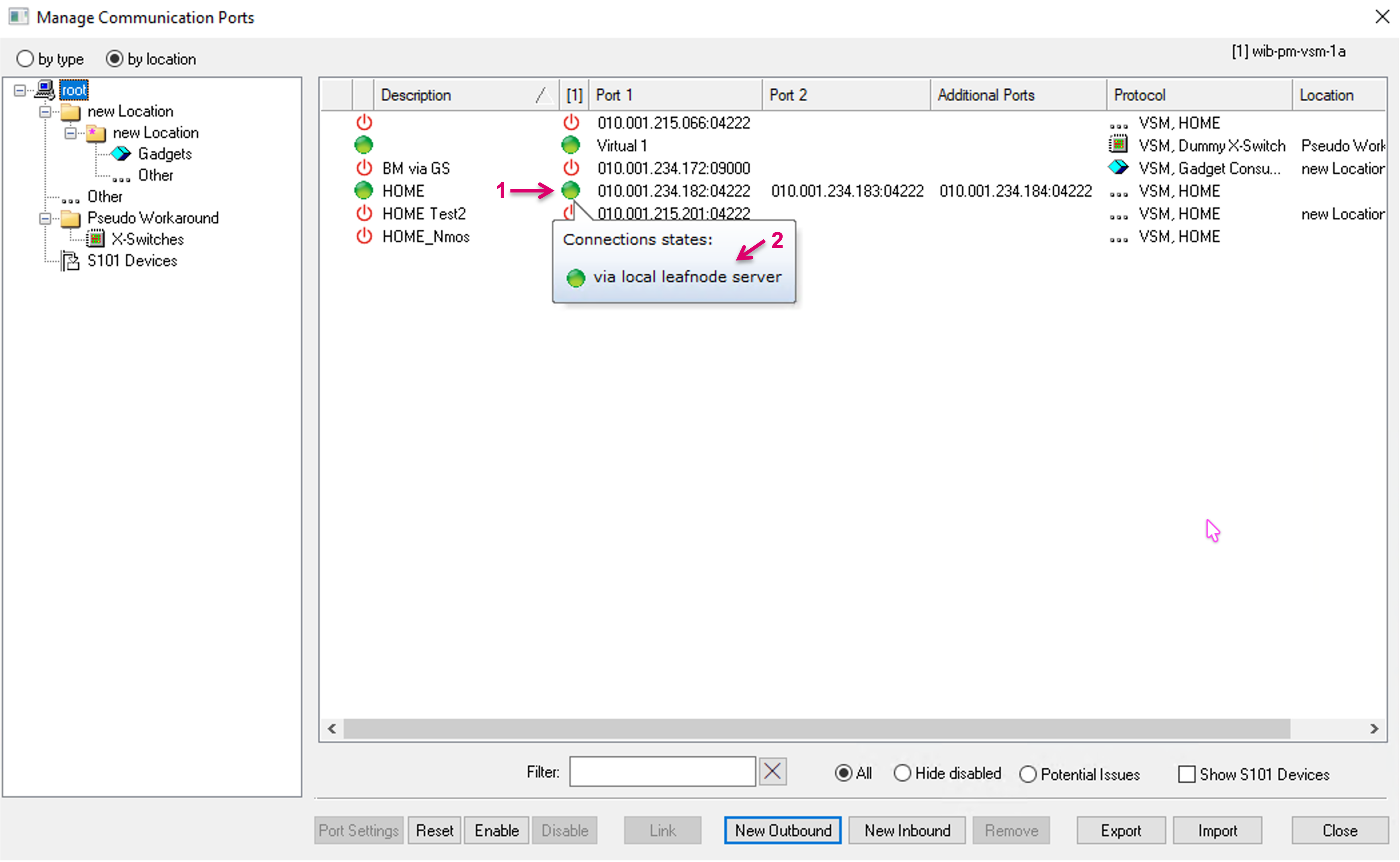
Once the port is created, it will show as entry in the Manage Communication Ports view (1). If the connection is established, the status icon will show green. When hovering over the status icon a little pop-up window shows details on the connection. If the HOME cluster is running, the network connection established, and the nats folder with included files is located in the correct location together with the vsmStudio.exe, the expected status should show green and read "via local leafnode server" (2).
To provide some context: In a background process, based on the selected HOME driver and respective IP addresses and settings, vsmStudio automatically starts a nats-leafnode Server for this HOME communication port. vsmStudio will choose a free port number and generate a temporary configuration file (1) that can be found in the nats folder (2). The HOME Server IP addresses, as entered in the communication port will be written as nats urls in the config file.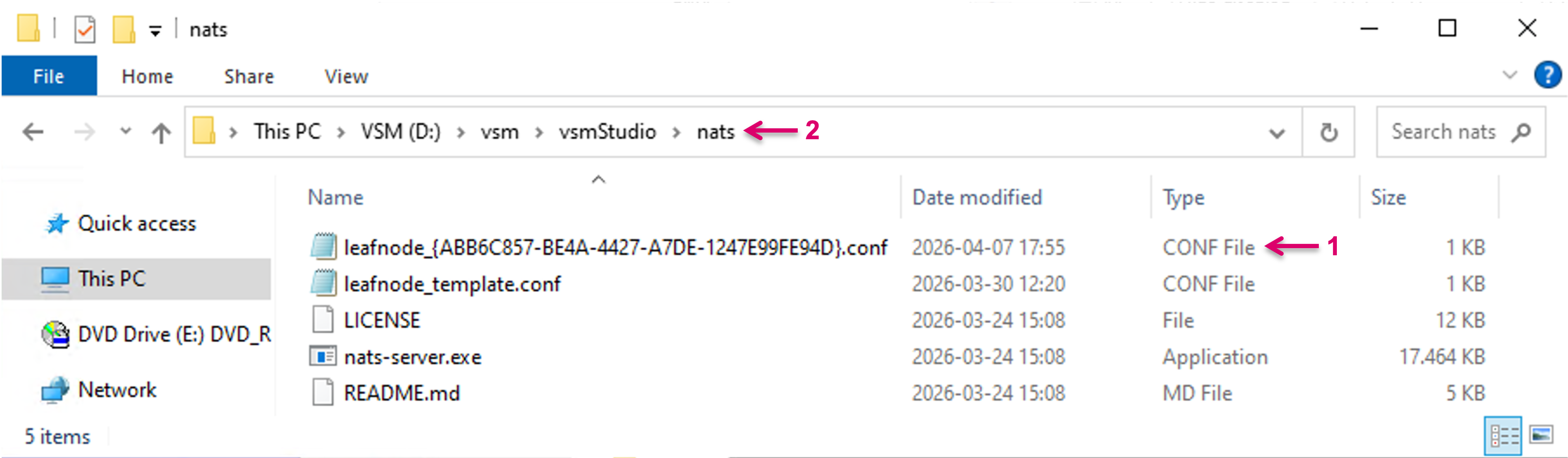
In the Task Manager (1) view, the nats-server.exe process can be monitored running (2).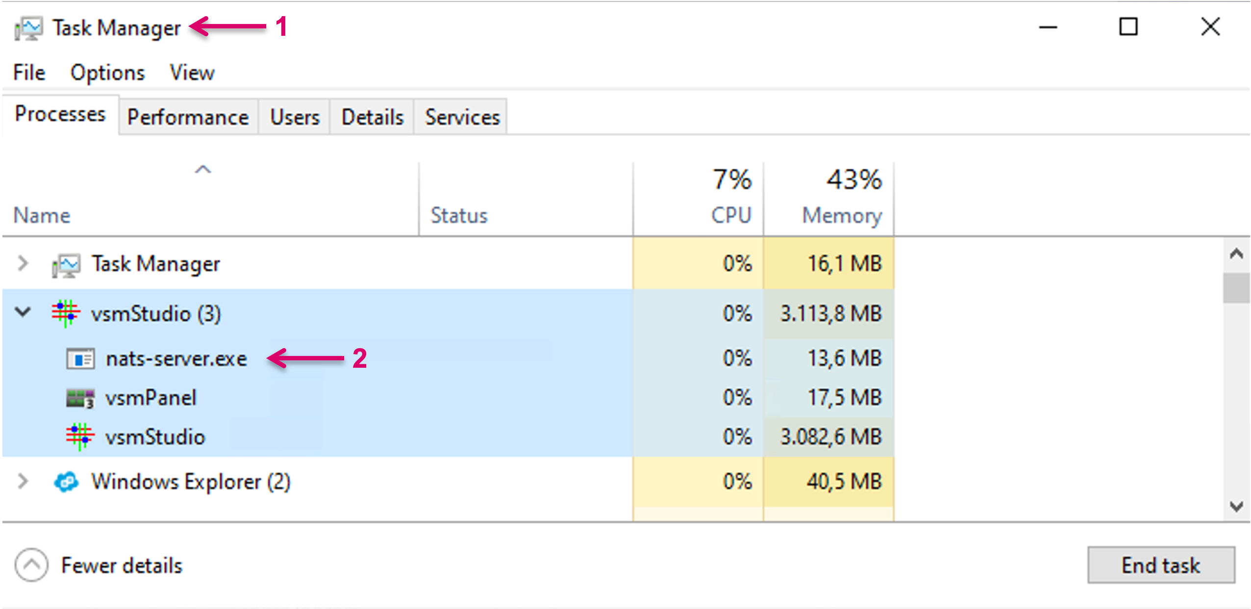
vsmStudio monitors the nats-server process and restarts it when needed, e.g., if a user accidentally close the console view window of the process (if enabled) or if the process is stopped via Task Manager. The same behavior is expected, in case of the process crashing.
If the communication port is disabled or vsmStudio is closed, the nats-server.exe process is automatically stopped and the temporary configuration file deleted.
While the nats-leafnode.exe is by default enabled and started automatically with every new HOME connection, it is possible to disable the Leafnode Server. It is strongly recommended to always interface via the NATS Leafnode Server and therefore not advised to disable. Still, for troubleshooting, etc., the respective option is available in the Attributes (1) of the respective Port. Please note that the parameter may show false initially although the Server is running. After switching it once to True and then to False (2) this parameter value will be activated. In preparation for the respective upcoming HOME release, vsmStudio is prepared to enter an AAA Key here (3). This Key will be generated on the HOME System and must then be added to the HOME interface in vsmStudio. Any change must be followed by OK and Disabling/Enabling the respective Communication Port.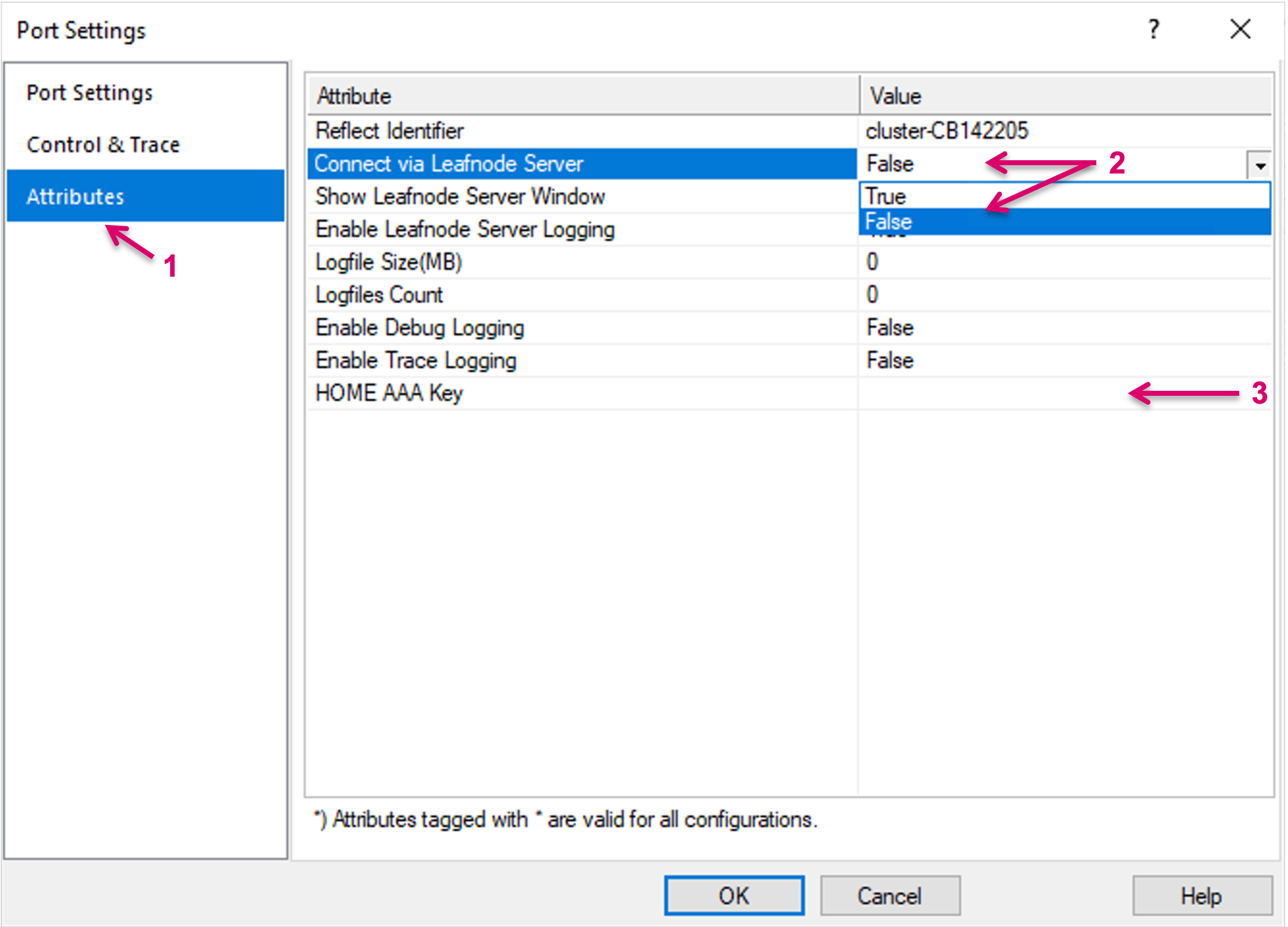
The HOME connection will be automatically established direct, to all of the configured HOME Server addresses set in the communication port, if:
- the "nats" folder is not available or
- one of the files within the folder is not available or
- a temporary configuration file can not be generated based on the template config file within the "nats" folder.
In this case, the status of the HOME communication port may still show green. When hovering over the status icon (1), the pop-up window will show details on the connection. If the HOME cluster is running, the network connection established, but the nats-server process is not running, the Connection states will show information on each separate HOME Server address (2).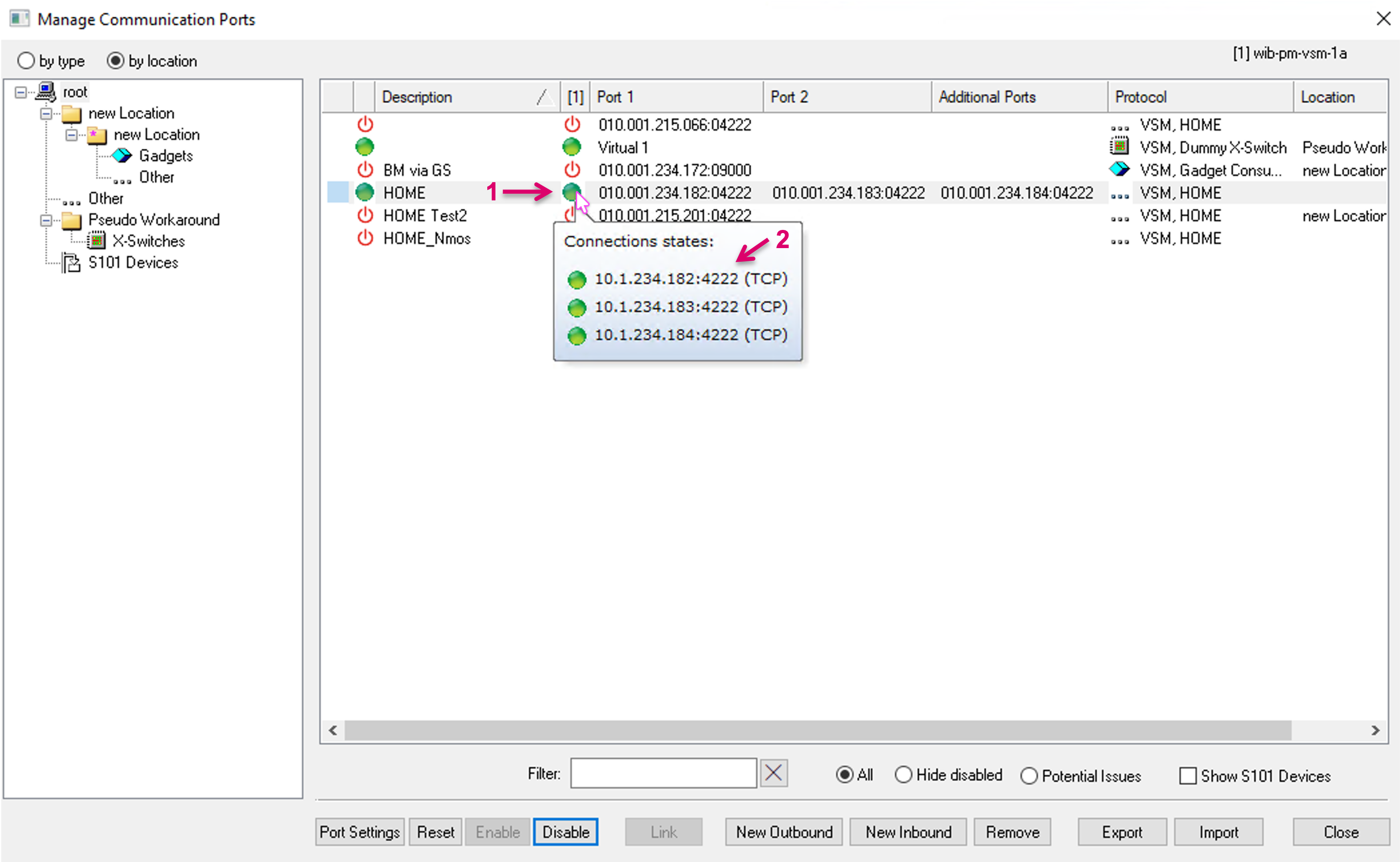
If connections to multiple HOME clusters are required, a dedicated Communication Port must be created for each HOME Cluster (1). A NATS Leafnode Server with its own configuration will be started automatically for each HOME interface.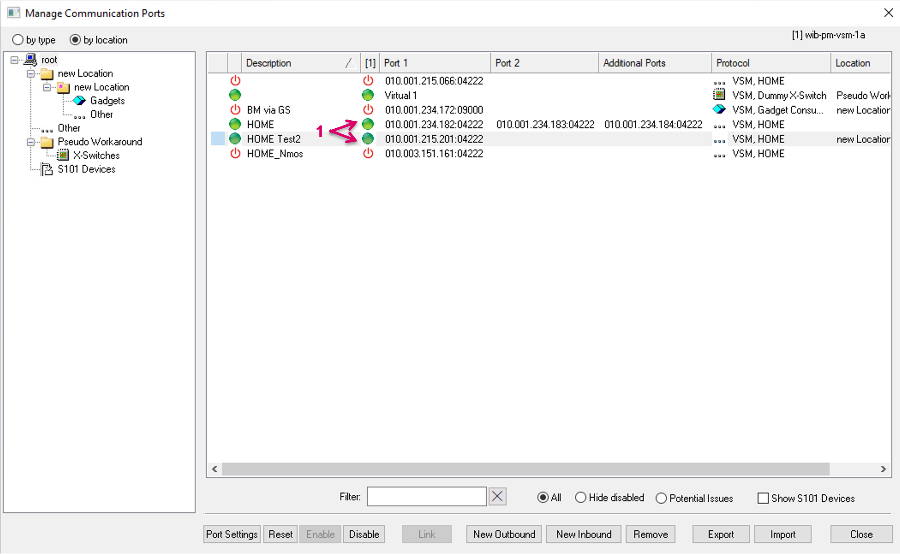
vsmStudio will start as many running instances of the NATS Leafnode Server as HOME Communication ports are enabled. Respective temporary configuration files (1) can be found in the nats folder (2).
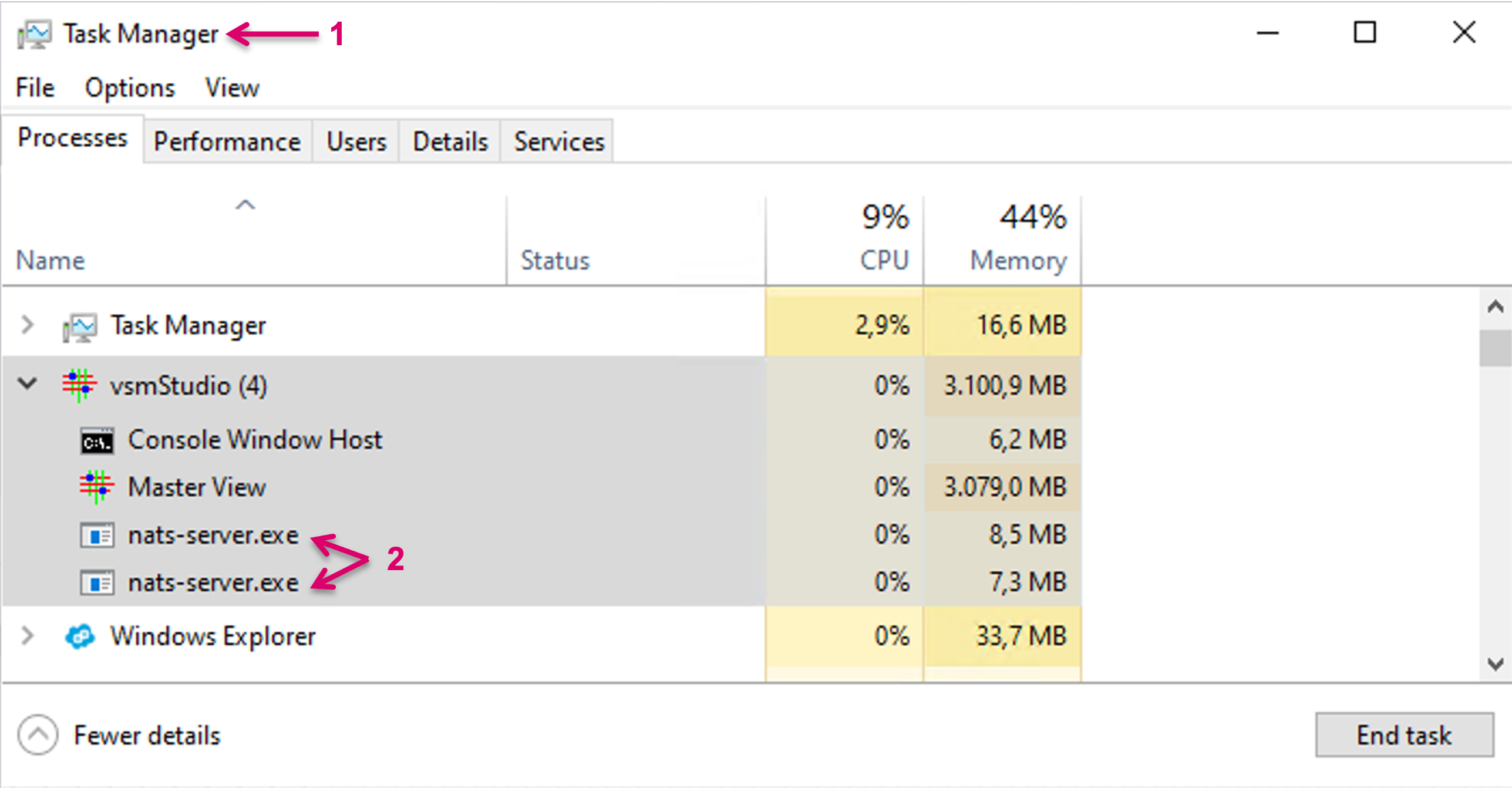
In the Task Manager (1) view, now multiple nats-server.exe processes are running (2).
Another option in the Port Attributes (1), allows to enable "Show Leafnode Server Window" (2). Mostly for troubleshooting purposes, if set to True, a separate window shows the live process (3).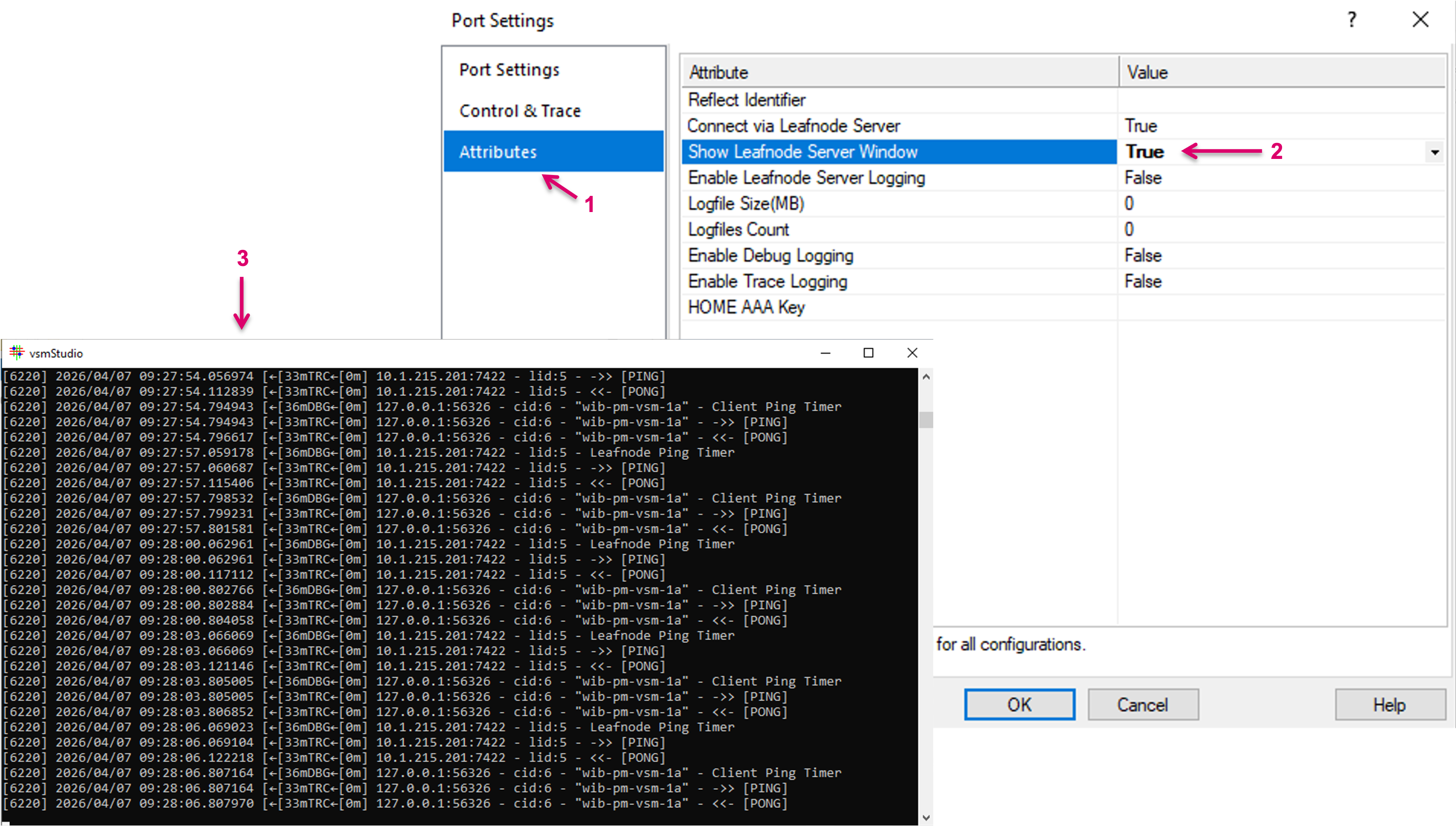
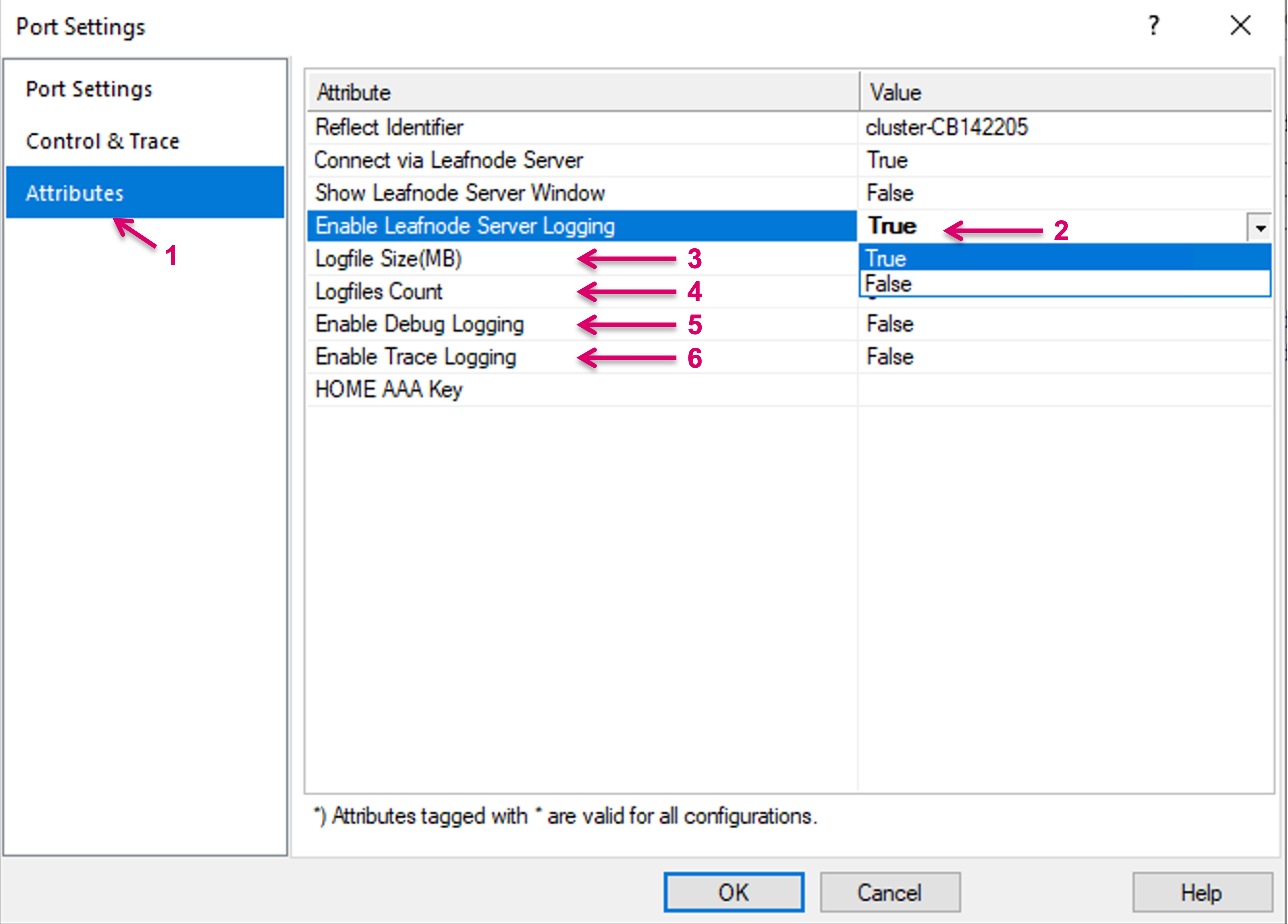
The NATS Leafnode Server has the option to write a Logfile. The logging can be enabled and configured and enabled in the Attributes window (1) of a HOME communication port.
There is one log file written per communication port, so each instance of the NATS Leafnode Server has its own log file.
The following attributes are available: "Enable Leafnode Server Logging" (2), "Logfile Size(MB)" (3) and "Logfiles Count" (4).
Further options allow to enable Debug Logging (5) for debug-level logging (useful for troubleshooting Leafnode Server connections) and Trace Logging (6), that enables verbose tracing of packets.
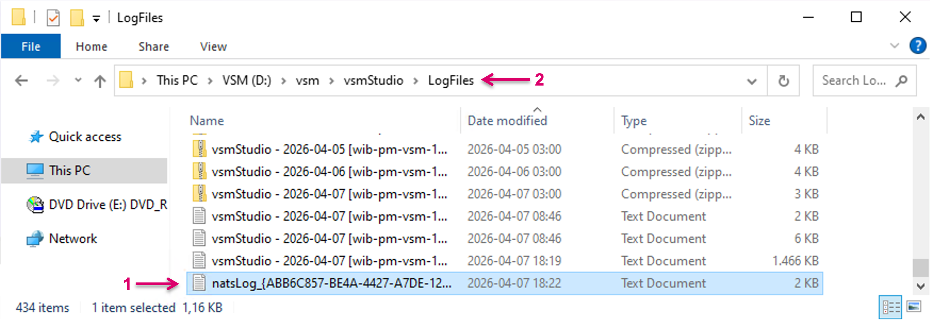
NATS Leafnode Server logs (1) can be found in the vsmStudio LogFiles folder (2).
Important note for early adopter projects, where a local Natsleaf service was already installed manually (1): This service must be manually deleted, to avoid that the "old" service can conflict with the new NATS Leafnode Server, which will be start automatically by the system. To delete the "old" Service, open elevated Command Prompt (“Run as Administrator”), type sc delete "SERVICENAME" and press Enter. Verify service removal with sc query or Services console.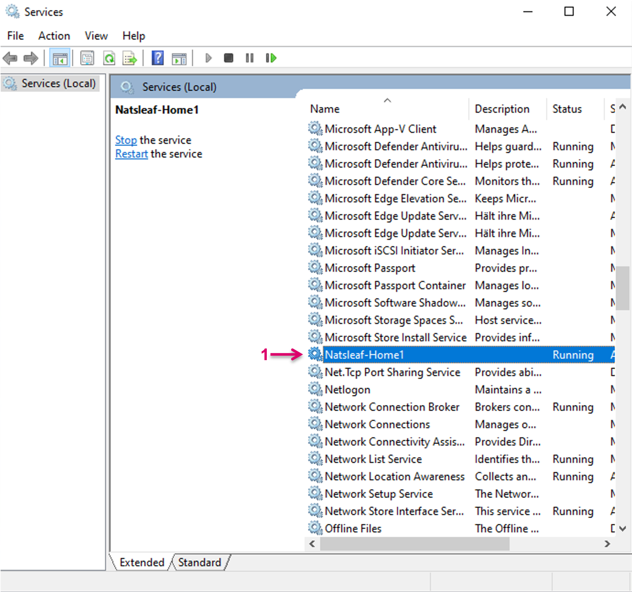
Internal xpoint reflection via Dummy X-Switch
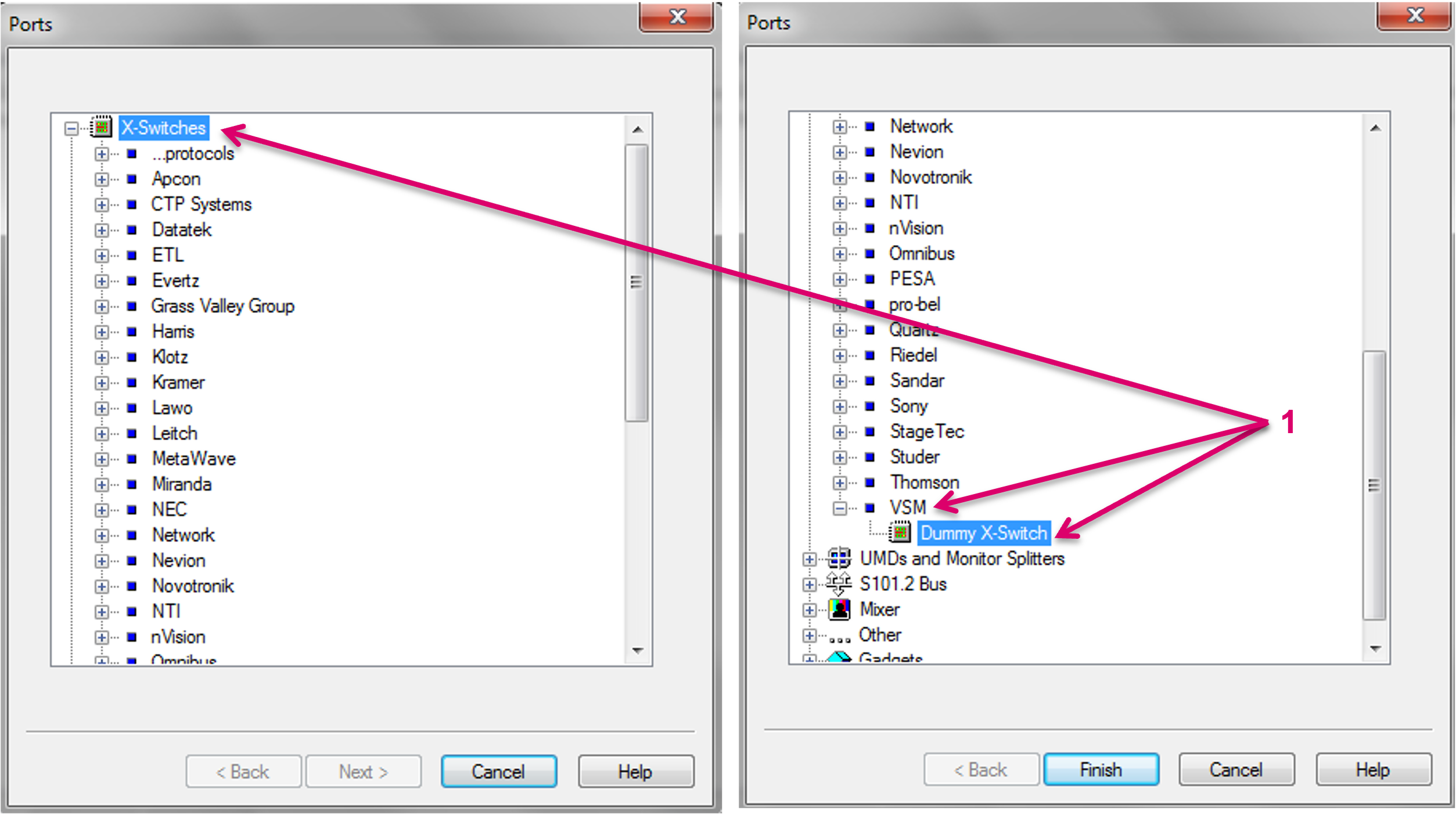
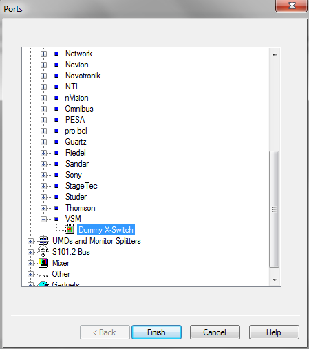
For configuration and testing purpose, vsmStudio offers a so-called VSM Dummy X-Switch to simulate crosspoint feedback of a router. It allows editing of a configuration without having access to the terminal devices that are to be controlled, e.g. set xpoints and store within a storage group/disc. The Dummy X-Switch can be selected from the driver list under X-Switches/ VSM.
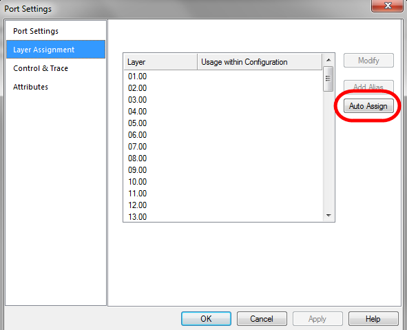
Select Finish to proceed to the Port settings view and navigate to the Layer Assignment page of the Port Settings window. All configured physical layers are assigned to the Dummy X-Switch by pressing Auto Assign.

This feature is only available for physical standard layers. For an offline reflector of network layers, please navigate to the System Settings dialogue and navigate to Layers. By right-click on the respective layer, a “dummy” Feedback can be enabled.
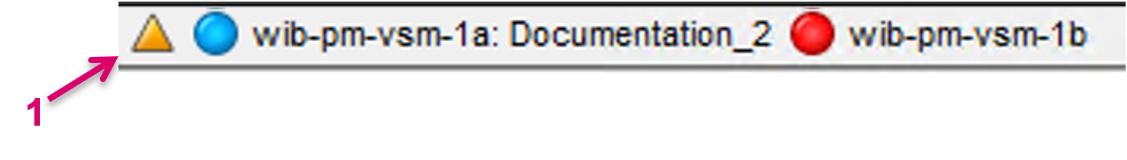
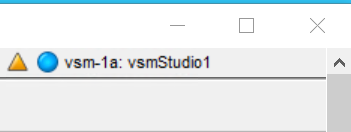
A visual warning in form of a flashing yellow triangle icon (1), next to the Server status on the vsmStudio toolbar, informs about an active Dummy Feedback.
The Dummy X-Switch connection should not be set up or at least be disabled on a Live vsmStudio Server.
S101.2 Bus
vsmGear will show under the S101.2 Bus protocol category, once connected to the vsmStudio Server cluster (1). Offline devices are listed as well.
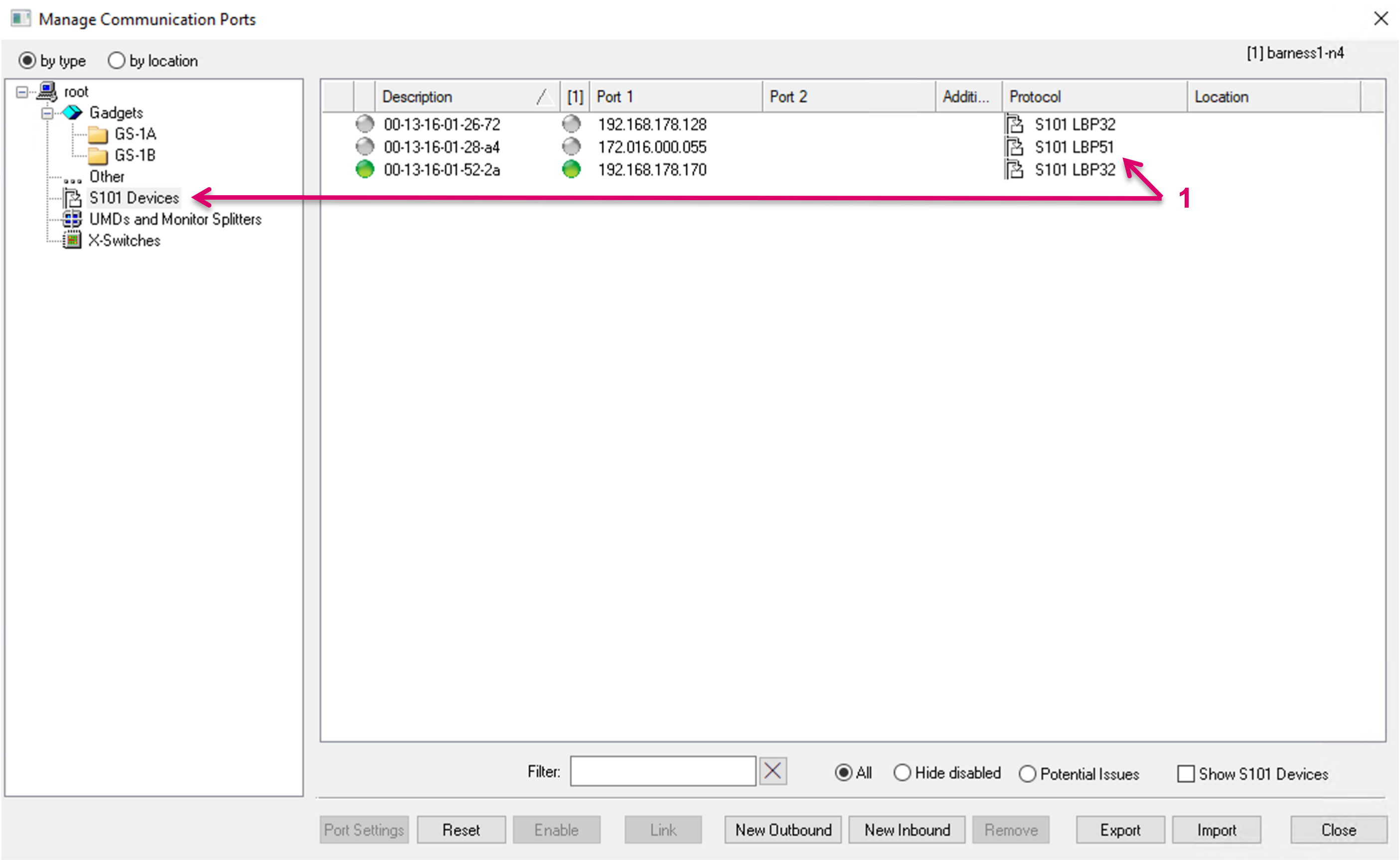
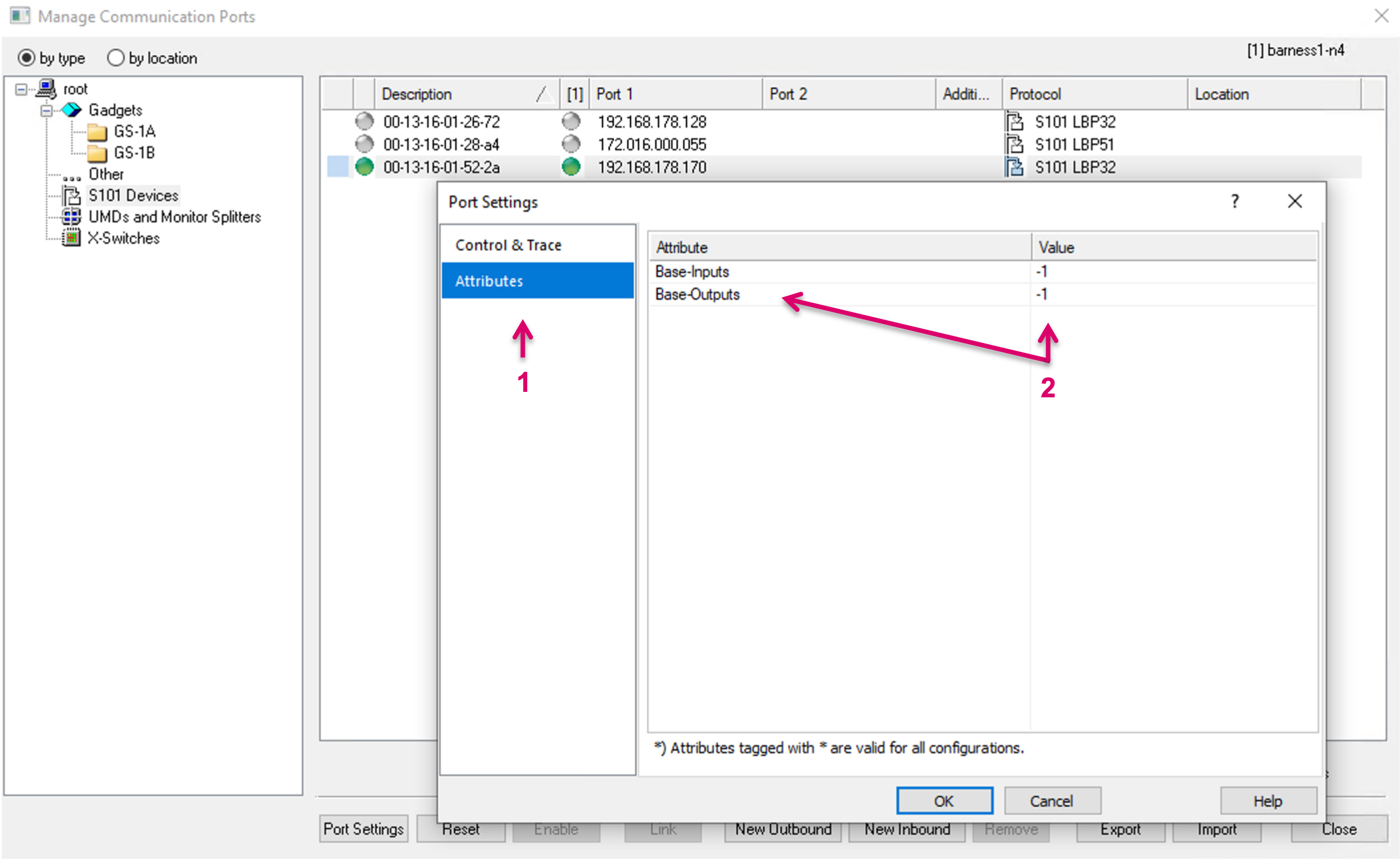
The following attributes are configurable via the respective property views (1) under Port Settings:
- Enable Trace
- Status GPI
- Base-Inputs (mapping the first GPI of the device to the respective GPI ID in the vsmStudio configuration) (2)
- Base-Outputs (mapping the first GPO of the device to the respective GPO ID in the vsmStudio configuration) (2)
 When a hardware panel is locked or unlocked, the change of the "Locked" attribute is also synced in the cluster.
S101 Devices cannot be assigned to a user created location.
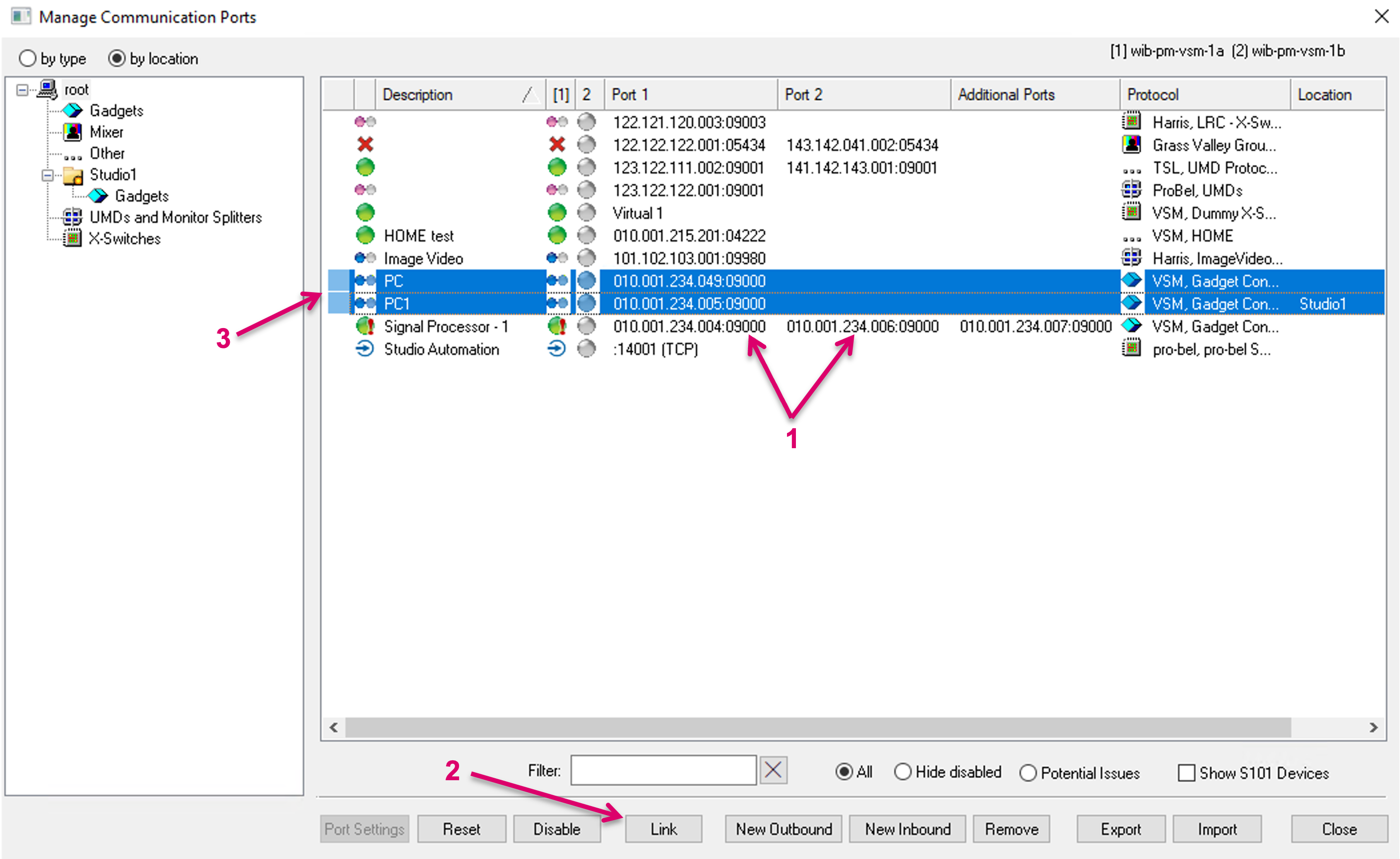
Linking Redundant Provider Port Connections
Some few devices and protocols are not able to handle redundancy internally. In this case, where Communication ports are delivering redundant information, separate port entries can be linked. With the new and current port management, Control ports are implicitly linked, once multiple IP addresses are assigned to one port (1). In the previous port management, multiple existing port entries had to be selected and linked manually. To support the previous approach and preexisting configurations, there is still a Link button at the bottom of the Manage Communication Ports dialogue (2), and two separate list entries could be both selected and then linked, using the Link button (3).
The linked ports are indicated by a specific link icon (1). The Link button is disabled if any of the selected entries has more than one IP address configured. On already linked ports, the entry fields for IP address 2 to 4 are disabled. Already linked ports can be Unlinked via the same button (2).
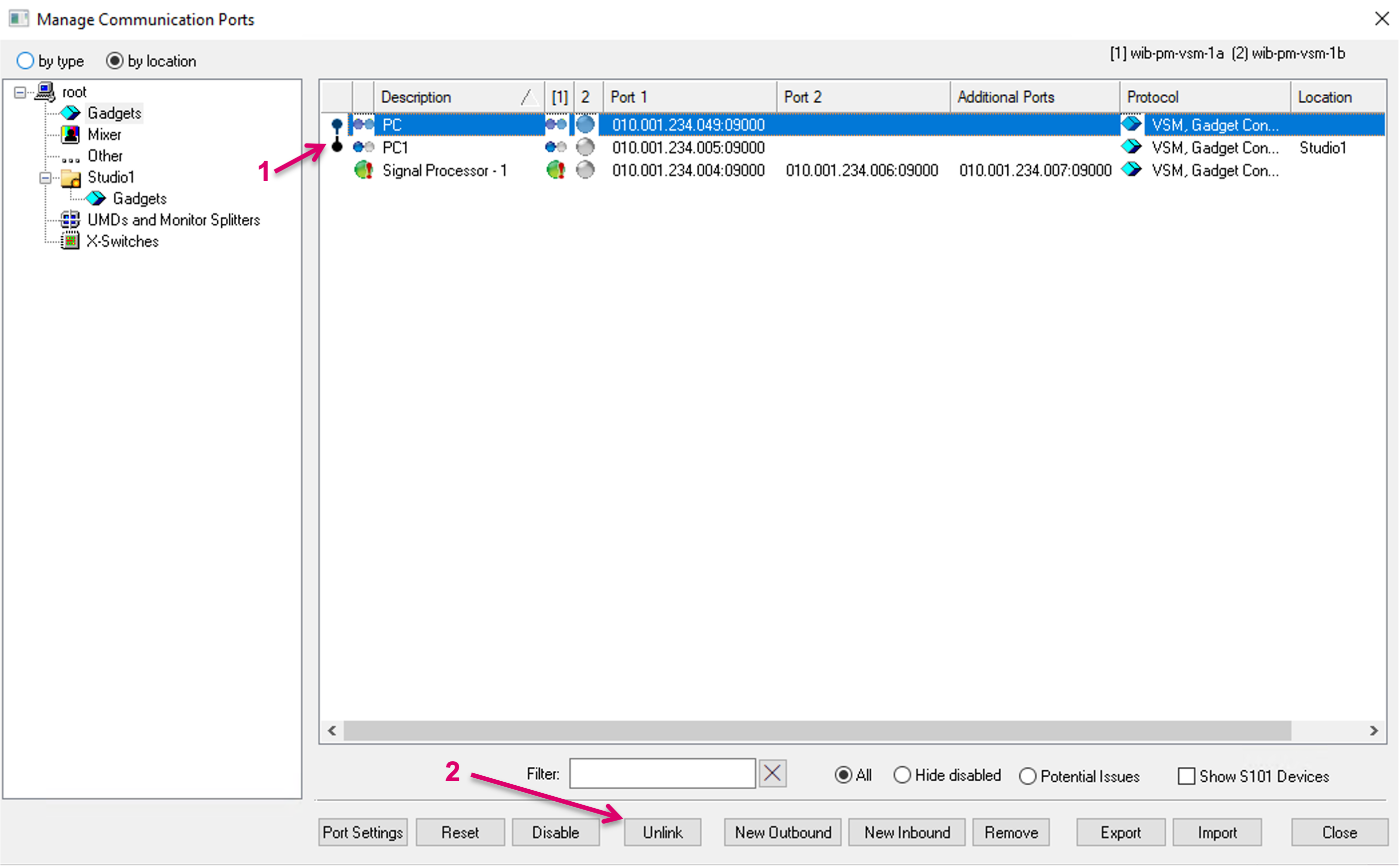
Make sure to unlink Control ports before deleting any of the respective entries.
Use of the previous link option is no longer recommended as it will be discontinued in the future. Existing Links will remain functional.
Export and Import Communication Port Configuration
It is possible to Export and Import Communication Port configurations. This includes the created ports as such, as well as underlying port settings.
Export
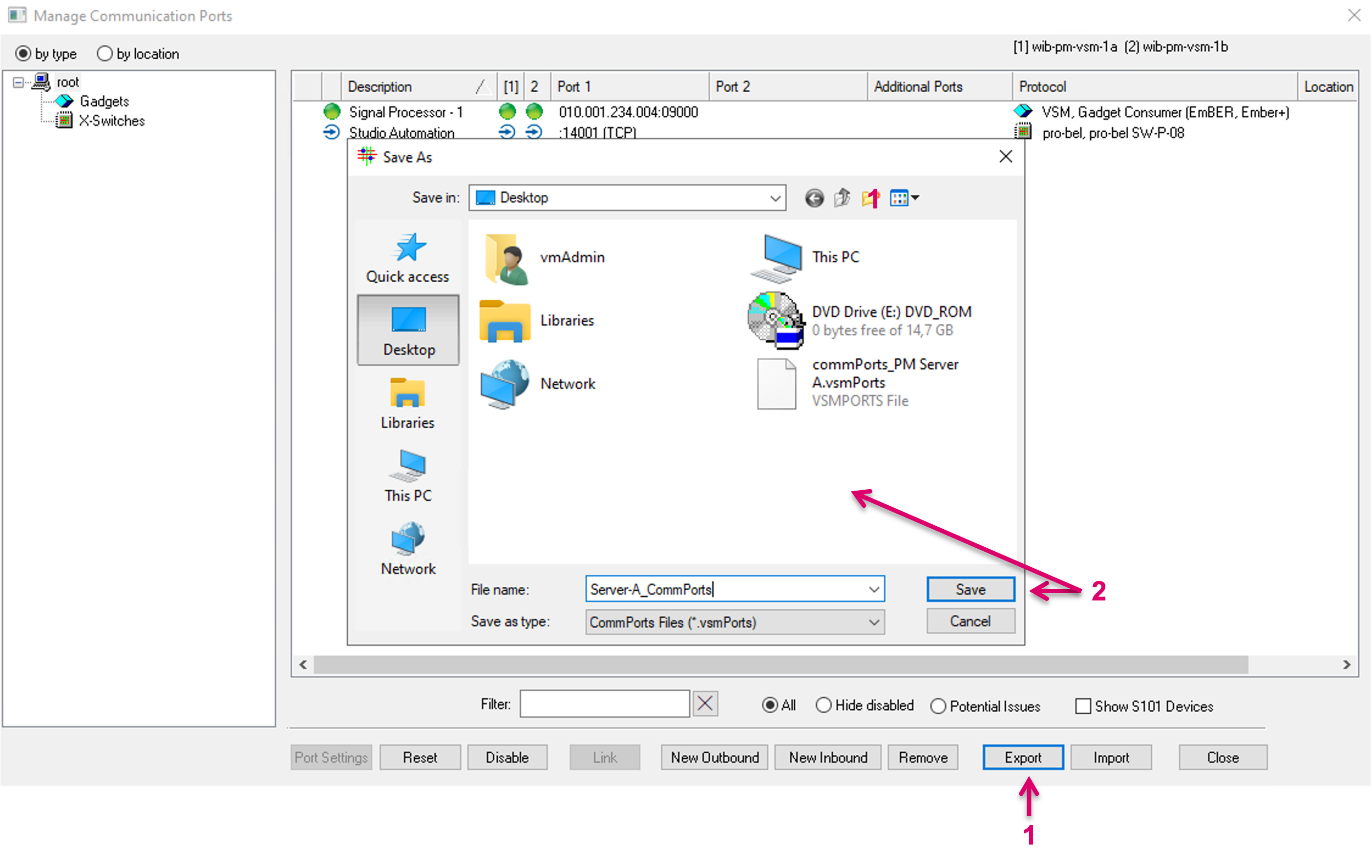
To Export all Communication Port configuration, click on the respective button at the bottom of the Manage Communication Ports window (1). Select a target location for the VSMPORTS configuration file followed by clicking Save (2).
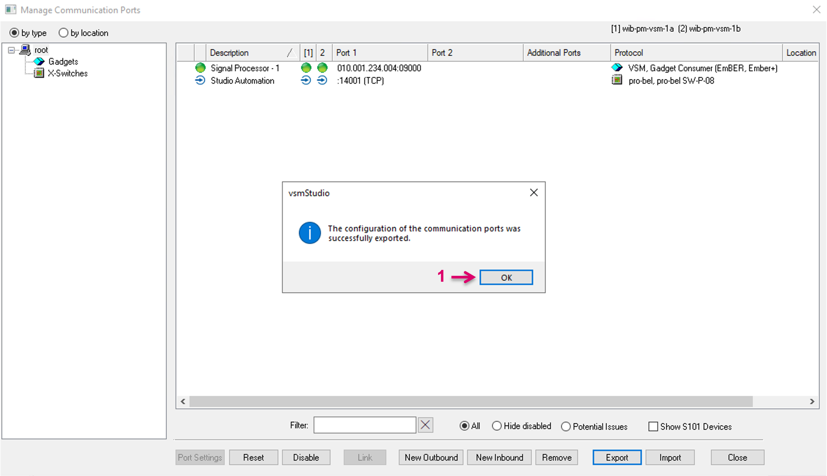
A success confirmation window will pop up. Confirm with Ok (1).
Import
To Import Communication Port configuration, click on the respective button at the bottom of the Manage Communication Ports window (1). Select a VSMPORTS configuration file followed by clicking Open (2).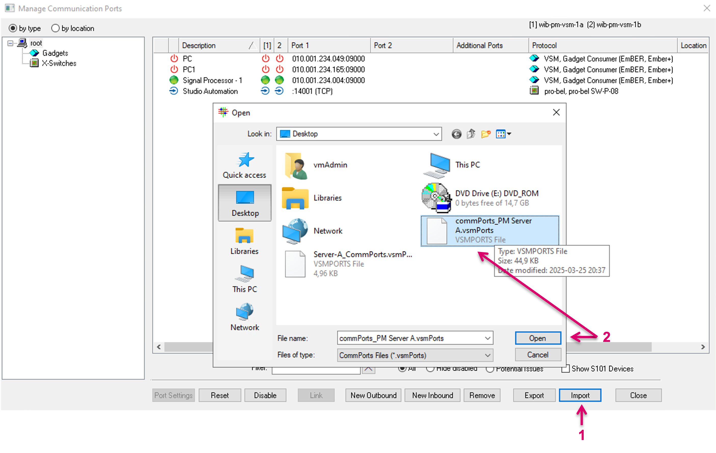
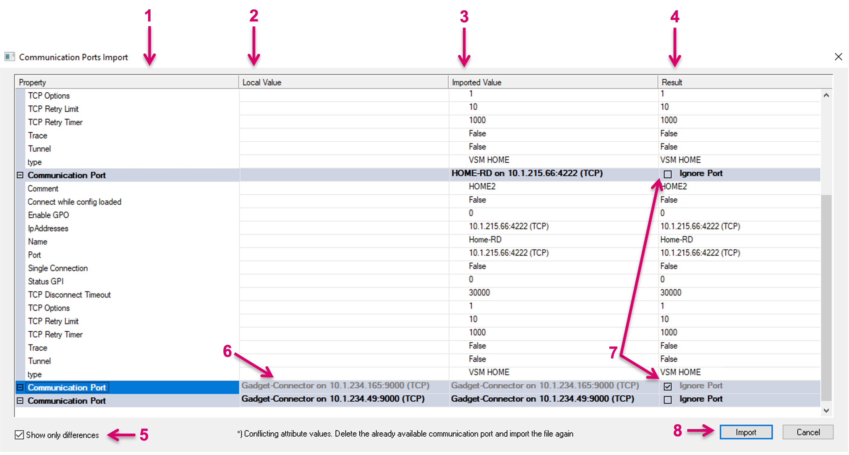
The opening dialogue provides an overview of all communication port settings (1) in a side-by-side comparison of current Local Value (2), the to be expected Imported Value as per selected configuration file (3), and the to be expected Result after executing the configuration Import (4). It is possible to display configuration differences only (5). If there is already a local value (6), that will be affected by imported data, it is possible to either ignore the whole port in the import process (7) or make selective decisions per underlying setting, e.g., a value is currently set to false, while it is set to true in the configuration file. A checkbox next to the respective parameter allows to select which data shall persist. After checking all settings, continue with clicking on the Import button (8).
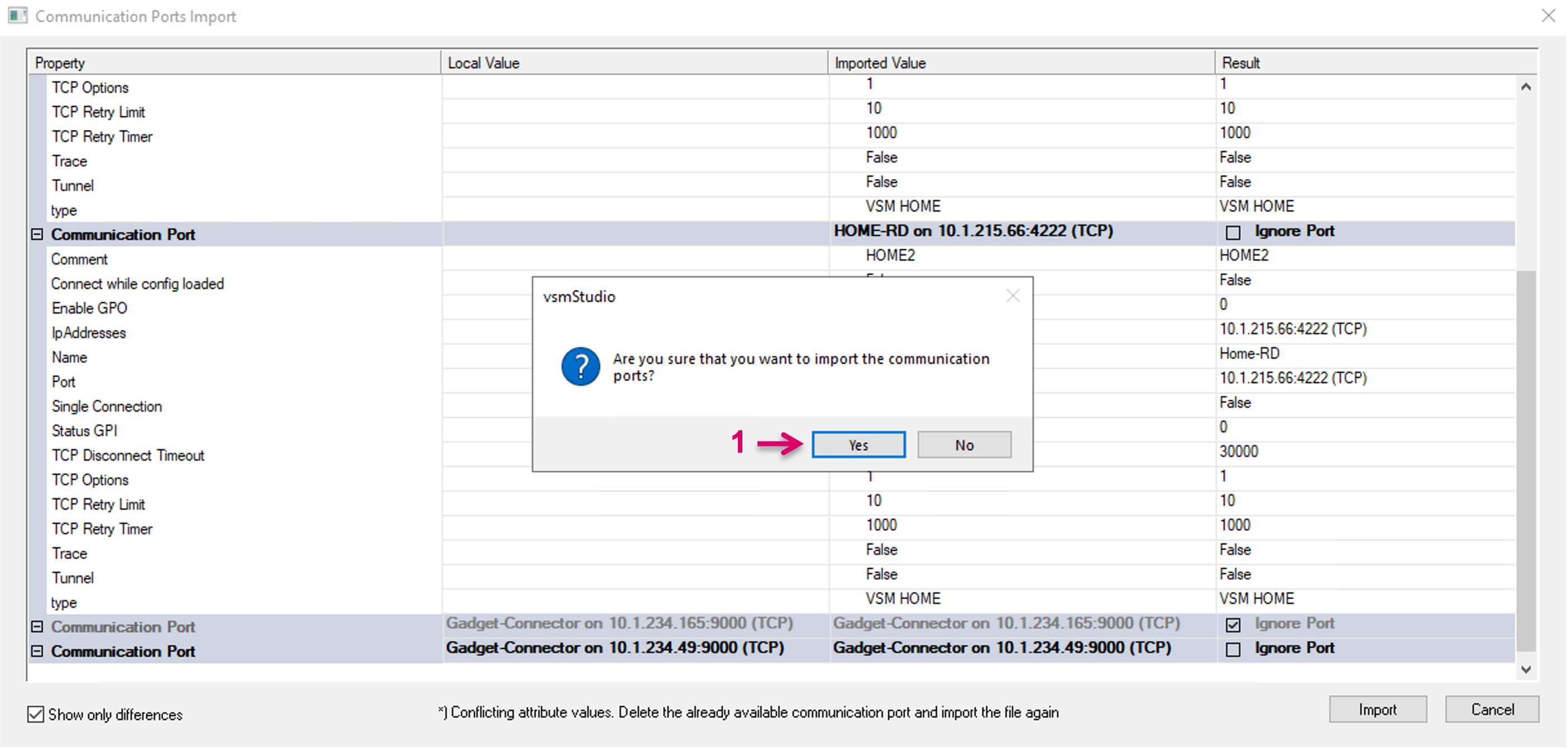
It is required to confirm the execution in the following pop-up window (1). Please note this action cannot be undone. Imported Communication Port data will be synced immediately across the Server cluster.
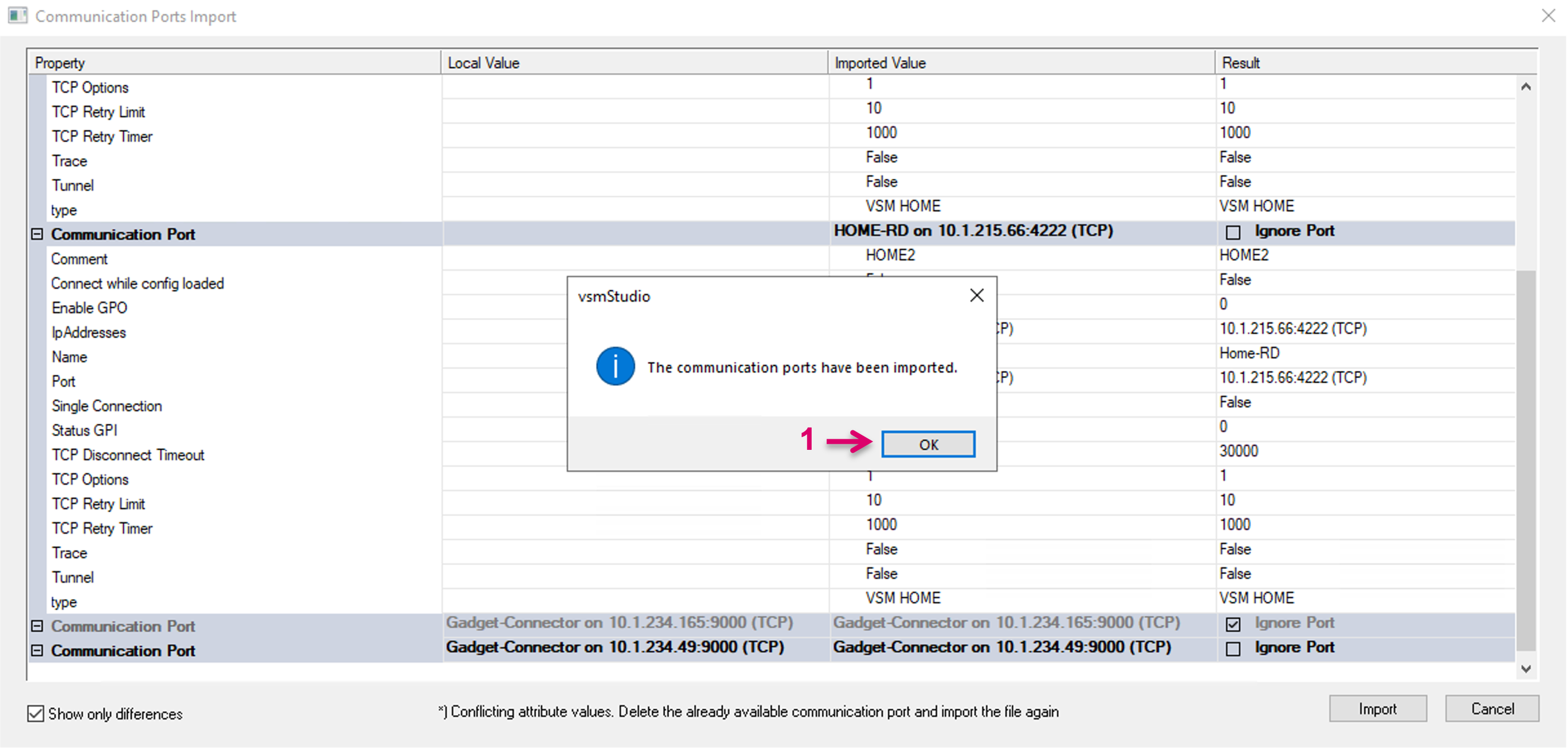
After import, success confirmation window will pop up. Confirm with Ok (1).
Registry Entries
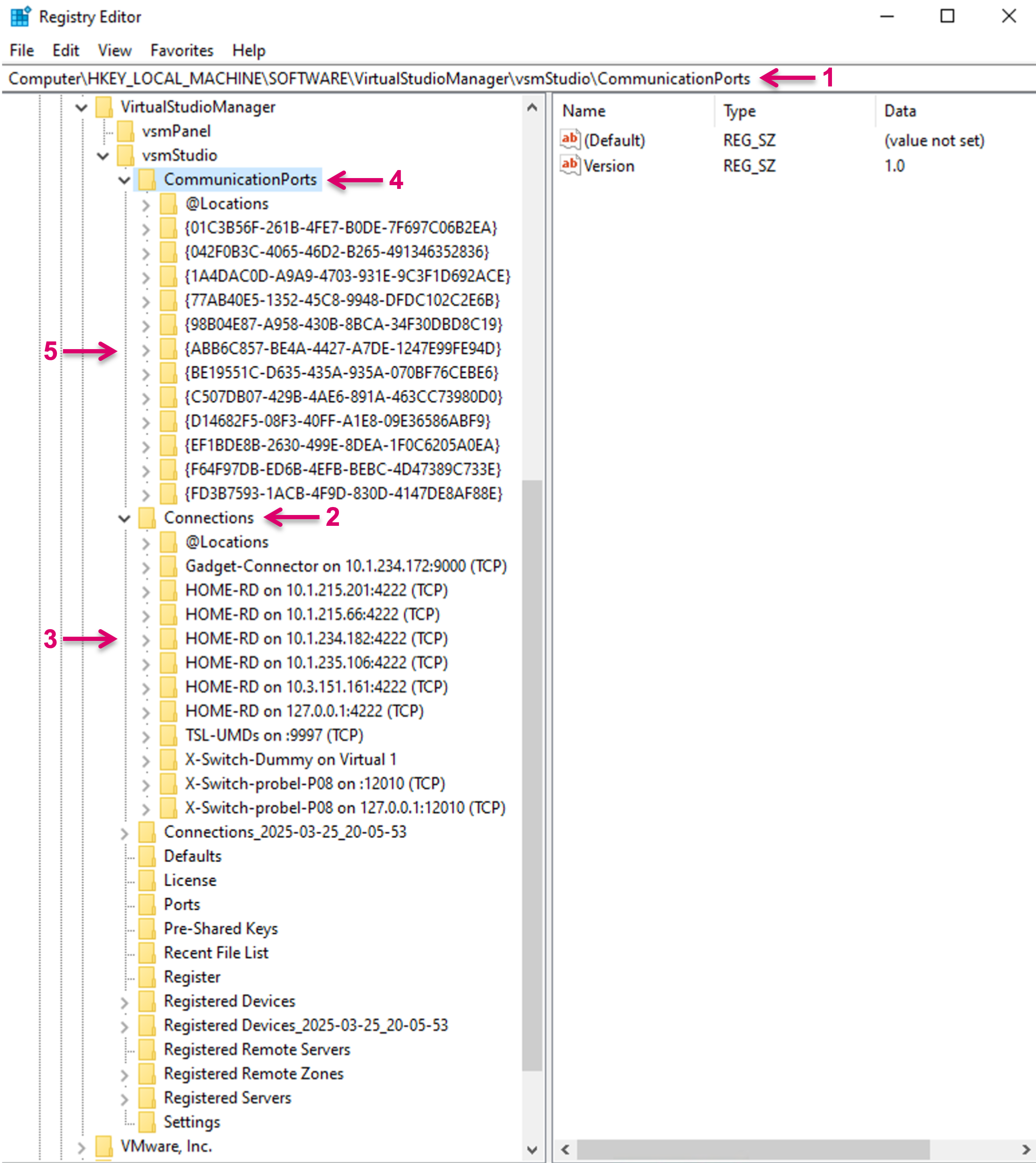
Communication Port Data is locally stored in the registry of the vsmStudio Server, in "Computer\HKEY_LOCAL_MACHINE\SOFTWARE\VirtualStudioManager\vsmStudio\CommunicationPorts" (1).
Previously the Communication Port data was located under "Connections" (2), entries were identified by a string containing the name of the protocol and the port (3). Since, after introducing the new Port management, where multiple IP addresses can be associated with one communication port, synchronisation problems could occur when the connections were modified via regedit and the "Port" or "IpAddresses" keys would not match the connection identifier.
To avoid inconsistencies when identifying connections in the registry and to facilitate better synchronization, communication ports are now identified by GUID (5). E.g., a connection key "HOME-RD on 10.6.38.123:4222 (TCP)" will be replaced with the GUID of the connection, {AF9C3269-3AD3-4010-B92A-706CE89DDDDD}.
To avoid problems when starting previous versions of vsmStudio, a new registry key "CommunicationPorts" (5) was introduced in addition. The management of the Communication Ports will make use of the new key. The "Connections" (2) key will be preserved.
To make use of the synchronisation of Communication Ports, a migration must be done first, selecting a reference server. The user has the possibility to cancel the migration. Before the migration takes place, vsmStudio must use the already existing identifiers.
In order to detect inconsistencies, the configuration of the Communication Ports will be checked everytime when vsmStudio starts.
It will be checked:
- if the Connection keys in the registry match the configured IP addresses and the Port keys
- if there are any duplicate IP addresses (same IP address configured for different Communication Ports)
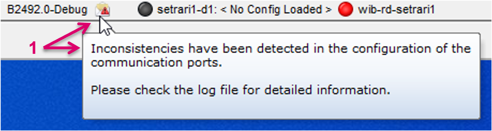
In case of any problems are detected, a log entry containing detailed information will be written. Ti inform the User, a dedicated icon will appear (1) in the top right corner of the main toolbar.
The configuration cannot be automatically corrected, the User will have to correct the entries based on the information provided in the log file.
This chapter covers the management of vsmStudio's communication ports prior to release 25.2.1.
Port settings must be made manually on every server in the cluster.
Symbol Legend for Connection Types: | |
| X-Switches / Routers |
| UMDs and Monitor Splitters |
| S101.2 Bus |
| Mixer |
| Other |
| Gadgets |
| Linked Connections |
New Port
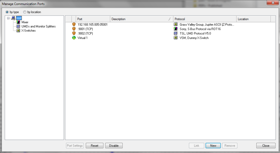
To configure a new interface, left-click the port symbol in the main menu bar or press F8.

This will open the Manage Communication Ports window in which existing ports can be viewed and new ones set up.
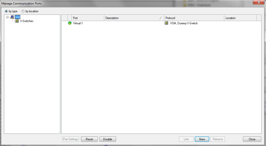
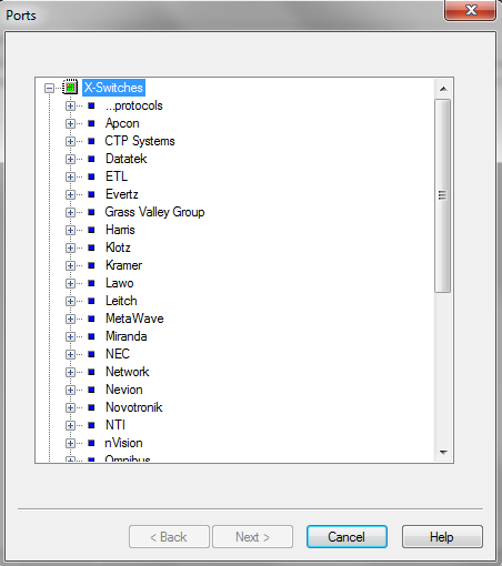
Left-click on "New" to open the Ports window and select the required driver from the categories: X-switches, UMDs and Monitor Splitters, etc.
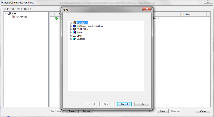
To open the categories, click the small plus sign located in front of the category name. If the required driver is found under the respective manufacturer's name, then select it.
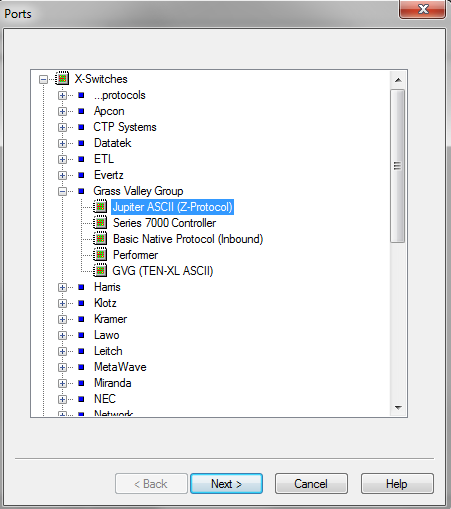
Then left-click Next to open another window listing the available ports.
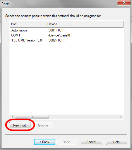
There are three different port types:
- Local COM interfaces at the server.
- Incoming connections to a defined port (TCP or UDP)
- Outgoing connections to an IP address with port (TCP or UDP)
If the required interface is not listed, it can be added by selecting "New Port".
Outgoing Connections
To set up an outgoing connection, enter IP address and port and select TCP- or UDP- Outbound. After naming the port, confirm by clicking OK.
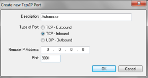
Incoming Connections
To set up an incoming connection, use the default IP address 0.0.0.0, enter a port, choose TCP Inbound, and enter a name for the new port. Confirm by clicking "OK".

COM Ports
It is not possible to add local COM ports here, as they are exclusively managed by the operating system.
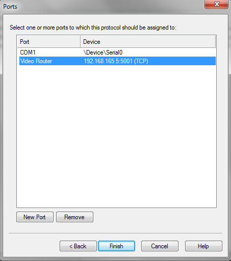
Finishing the Setup
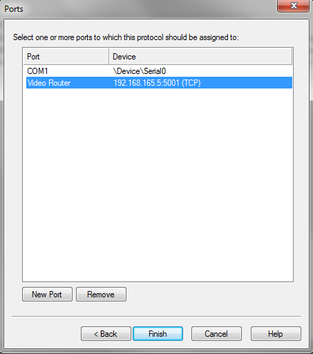
In each case, finish the set-up process by selecting a port and clicking "Finish". The new interface is added to the Manage Communication Ports window.
The Port Settings now automatically opens to configure further settings for the terminal device.
Port Settings
The vsmStudio software allows each port to be adapted individually. To do so, access the window Manage Communication Ports through the main menu bar or by pressing F8.
Use the driver categories on the left to sort the list or select root to view all configured ports.
Select a port and click Port Settings - this opens the Port Settings window.
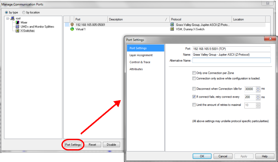
From here you can configure further settings for the terminal device. Use the tabs on the left to access the different pages.
Note that the pages and their options vary depending on the driver; three different driver types are possible:
- Under monitor/In-monitor display or Multi-viewer
- Router or Automation
- Video Mixer with tally and mnemonic
UMD/IMD or Multi-Viewer
If the driver is a UMD (IMD) or multi-viewer, then the Port Settings will look as follows:
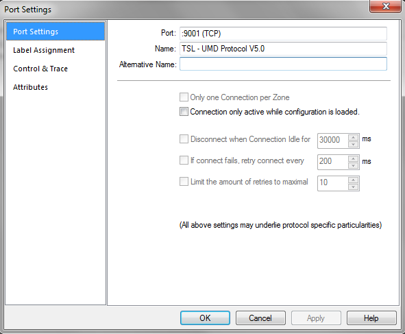
The most important settings are:
Port Settings Page
In the Name field, a unique name for the terminal device must be entered.
Label Assignment Page
In this window, a target (Outbound) or source (Inbound) is assigned to each ID. Double-click on the relevant ID to open a window in which the signals can be assigned.
|
|
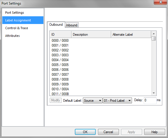

By assigning a target or a source (Inbound), it is possible to define whether the system will send a corresponding ID (Outbound) or an external label layer (Inbound). Under Outbound, it is also possible to specify that the system sends the name of the source that is connected to the target to this ID. Tally information is transmitted directly as well. Inbound means that the VSM control system receives a label and transmits it to the external label layer of the source.
Router or Automation
If the terminal device for the interface is a router or automation, then the Port Settings will looks as follows:
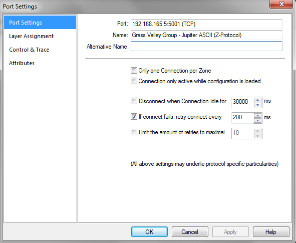
The most important settings are:
Port Settings Page
In the Name field, a unique name for the terminal device must be entered.
Layer Assignment Page
Depending on the driver chosen, one or multiple layers are displayed here. By double-clicking the relevant layer, a new window opens in which the layer can be assigned.
|
|

Select a layer using the drop down menu. If a router is assigned, the default setting The attached device is a outer is selected for the control direction.
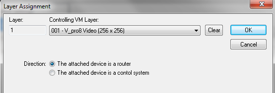
If a virtual layer (vLayer) is chosen in the drop down menu, then it is most likely that a controlling instance is connected. In this case, the control direction must be changed to The attached device is a control system. When this function is activated, the layer acts as a router that can be controlled by an automation system.
Video Mixer
If the terminal device for the interface is a video mixer with tally and mnemonic, then the Port Settings will looks as follows:

The most important settings are:
Port Settings Page
In the Name field, a unique name for the terminal device must be entered.
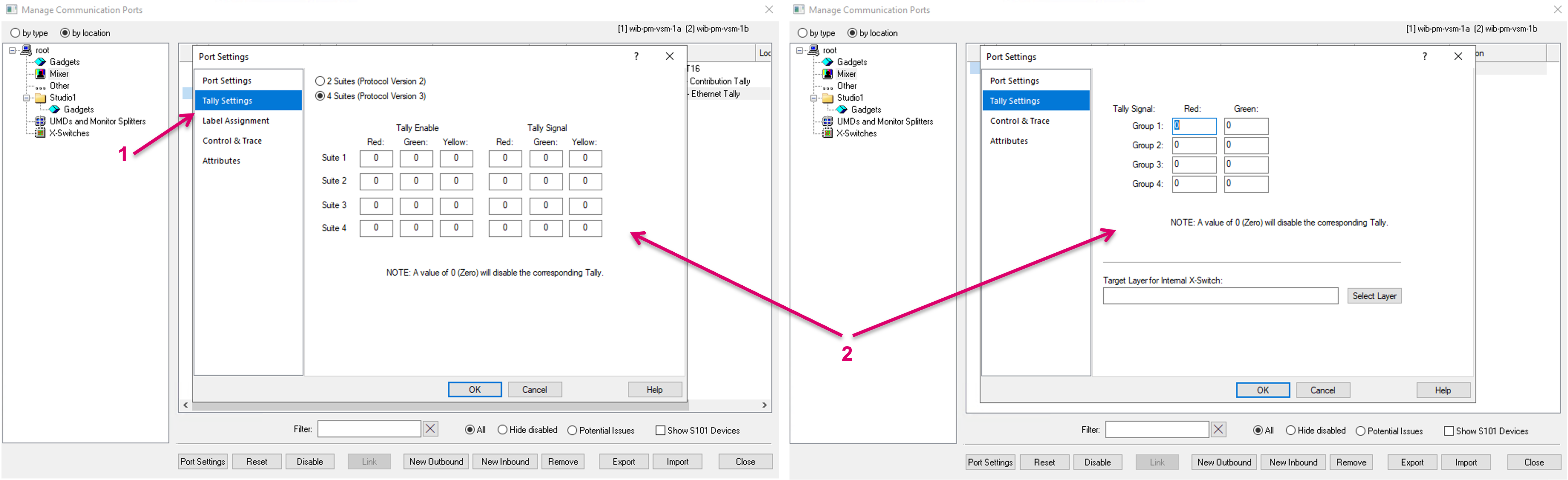
Tally Settings Page
The fields under Tally Signal serve to define where the mapping of the GPIOs starts:
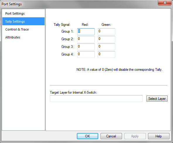
Use Select Layer to select the relevant, configured video mixer layer.
These areas must not overlap. Depending on the driver chosen, the window may differ from the screenshot shown above.
Port Settings
Depending on the driver type, the following Port Settings may also be available.
One Connection per Zone
Only one connection per zone is an option which exists to facilitate devices which have implementation issues in some way. It should only be used with devices which have problems with accepting multiple connections or have any implementation detail that prohibits clean multi connection control. Only one connection per zone ensures that only one vsmStudio server will open a connection to this device and currently (subject to change in future), this will always be the current primary server. Since Only one connection per zone effectively limits the connection to one single server, the other servers cannot perform any redundancy traffic routing, in case the primary server, tagged as Only one connection per zone, is not able to connect to the device. Please note that Gadget devices cannot be Only one connection per zone.
Duration until Disconnect
If a terminal device loses its connection to the server, the relevant IP port may not close. It is possible to define a time frame in milliseconds under Disconnect when Connection Idle for... after which vsmStudio disconnects automatically.
Duration until Re-connection Attempt
If the connection was lost or the terminal device was turned off, the VSM control system will attempt to re-connect the port after a defined period of time if this attribute is activated. This time frame can be entered in milliseconds under If connect fails, retry connect every... and will be used as default.
Number of Attempted Re-connects
If a terminal device loses its connection to the server cluster, vsmStudio will try to re-connect the port. The maximum number of re-connect attempts can be defined in the field following Limit the amount of retries to maximal... When this maximum number is reached, the port must be re-created manually.
Control & Trace
The Control & Trace page provides access to the following options:
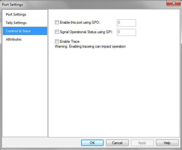
Deactivating Ports through GPO
Every port can be activated or deactivated with a GPO (see GPIOs). In the field Enable this port using GPO, it is possible to enter an unassigned GPO that will activate or deactivate this or multiple ports. It is irrelevant whether the GPO is physical or virtual. The function can be provided with a logic and assigned to operating elements.
Signal Monitoring via GPI
Each port with a so-called heartbeat can be monitored with a GPI. To do so, an unassigned GPI that will monitor this port can be chosen following Signal Operational Status using GPI. This GPI can be either physical or virtual. Within the configuration, this function can be provided with a logic that creates alarms and can be assigned to operating elements.
Service Tool Trace
Check Enable Trace to activate the trace mode. It provides additional information in the CommTrace.
This function may affect the performance of your system.
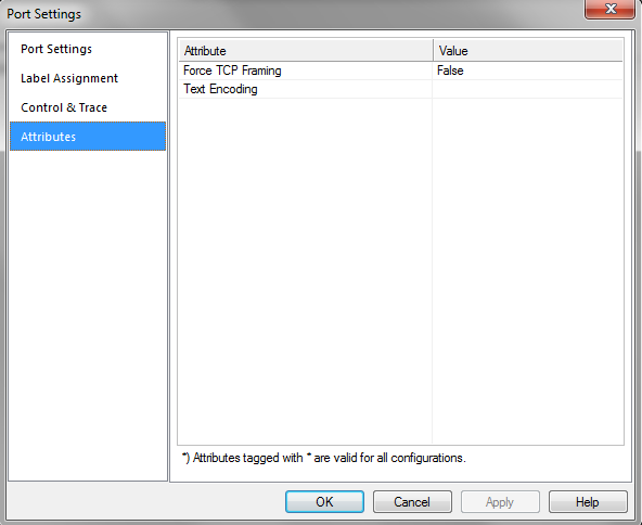
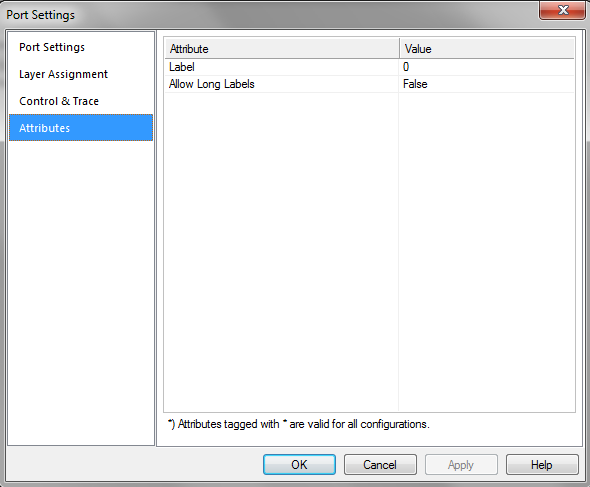
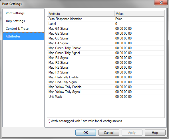
Attributes
The Attributes page displays attributes for the terminal device. Note that these will vary depending on the driver - below are three examples:
Attributes: UMD | Attributes: Router | Attributes: Video Mixer |
Port Monitoring
Using the Manage Communication Ports window, it is possible to spot which ports are active and in working order, and at which points, if any, problems are occurring.
The symbols in front of the listed ports have the following meaning: | |
| A connection is confirmed and operating. |
| A connection is confirmed but there is no valid communication. |
| A connection is confirmed, but there has been no communication in the last 15 seconds. |
| A connection is being established and pending. |
| A renewed connection is being established and pending. |
| A delayed connection is being established. |
| Connection failed. |
| Connection is disabled. |
| Connection is on standby (One zone Connect). |
| Connection is deactivated through a GPI. |
| Port has actively stated that it is the passive connection in a linked set or connection. It is situational when and if that happens and therefore the icon may vary, e.g. at times also the orange dot could be displayed. The result in terms of status and functionality is the same. |
| Inbound port (not showing any Connection status) . |
VSM Dummy X-Switch
To simulate feedback from a router locally on a computer, vsmStudio offers a so-called VSM Dummy X-Switch. It allows the editing of a configuration without having access to the terminal devices that are to be controlled.
The Dummy X-Switch connection should not be set up or at least be disabled on a Live vsmStudio Server.
The Dummy X-Switch can be selected from the X-Switches -> VSM driver list.
|
|
Select Finish to open the associated input mask, and navigate to the Layer Assignment page of the Port Settings window. Existing layers are assigned to the Dummy X-Switch by pressing Auto Assign.
In the Manage Communication Ports window, a green dot indicates whether a connection to the VSM Dummy X-Switch is in place:
A visual warning in form of a flashing yellow triangle indicator, next to the Server status on the vsmStudio toolbar, informs about any active Dummy Feedback.
vsmGadgetServer
There are individual protocols that cannot be selected directly through the vsmStudio software, but communicate via vsmGadgetServer. In this case the control system must be connected to the vsmGadgetServer, so that it can establish a connection with the terminal device.
The protocol to connect to vsmGadgetServer is called Ember+ (for further details please refer to the vsmGadgetServer documentation).
Ember+ for parameter control
Linking Redundant Provider Port Connections
This chapter describes how to link two port connections in vsmStudio, which are delivering redundant information. This is only required for devices and protocols that do not properly handle redundancy internally.
In the Manage Communication Ports dialog select both provider connections from vsmGadgetserver, which you want to link.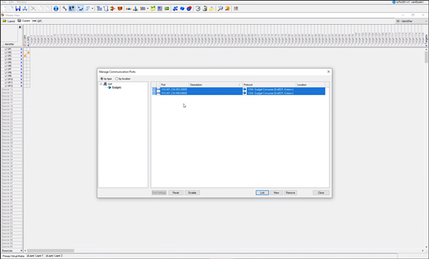
Once two connection are simultaneously selected, the Link button at the lower edge of the window becomes active. Click it and a confirmation window will pop up, asking your to confirm your action. To link the selected ports, click Yes.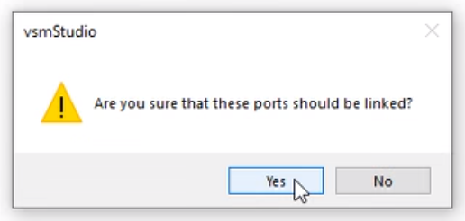
The Manage Communication Ports dialog now shows the two ports linked, indicated by a solid line symbol connecting both connections.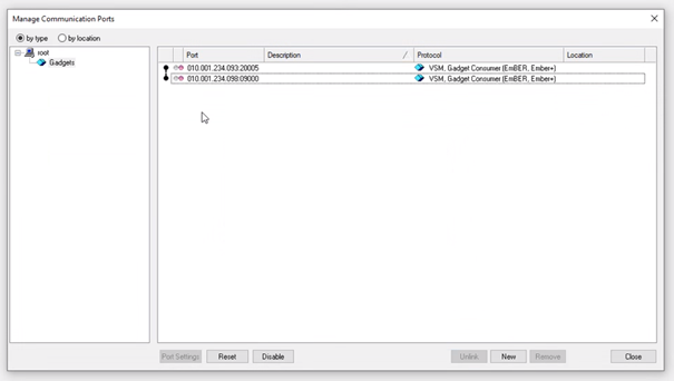
Ports are successfully linked now.