Interface - Plura Timer with C100 vm_dmv
Table of Contents:
Introduction
This chapter addresses the integration of Plura Studio Production Timers and Lawo DMV.
The following configuration example allows the operation of Timer settings via Plura Hardware and the display of the resulting Up-/ Downtimer on Digital Clock items of a Lawo DMV.
Create Stopwatch in DMV Configuration
Aside a working Plura Timer system, at least one digital_clock element must have been created in the DMV configuration. To check or create, connect to the DMV master node via webBrowser UI and navigate to the respective physical head instance and digital_clock item (1). Once created, you there can also find the stopwatch parameters (2).
Example path: {multiviewer.global.configuration.head[0].digital_clock[0].stopwatch}
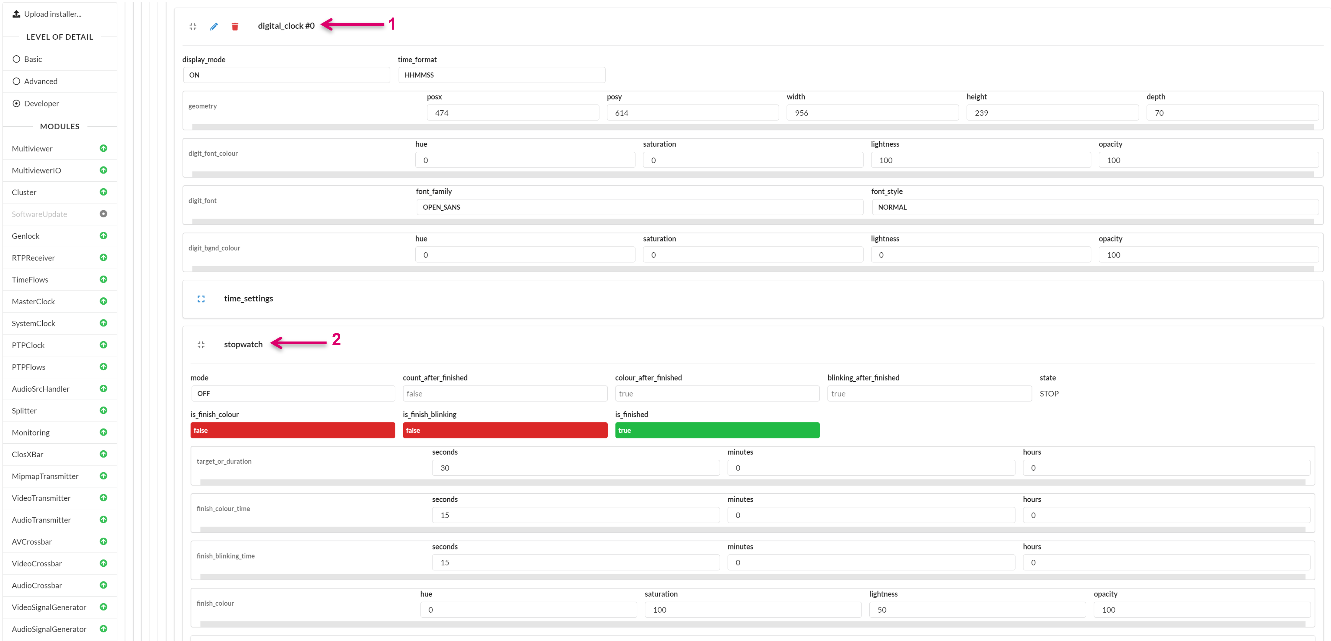
Within the DMV, the Clock related parameters are located on Head level.
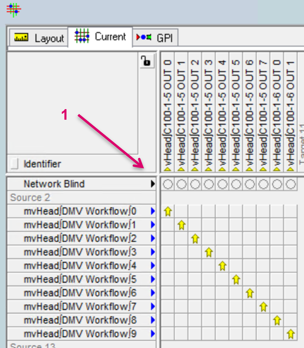
With the Distributed Multi Viewer module in use, DMV Heads are in general managed as a dynamic pool and hence also the reference path to underlying parameters could change. To determine which Head Clock parameters are related to a specific monitor target and can be linked accordingly with Plura parameters, the dynamic physical to virtual Head assignment must be executed beforehand (1).
Setup Communication Ports
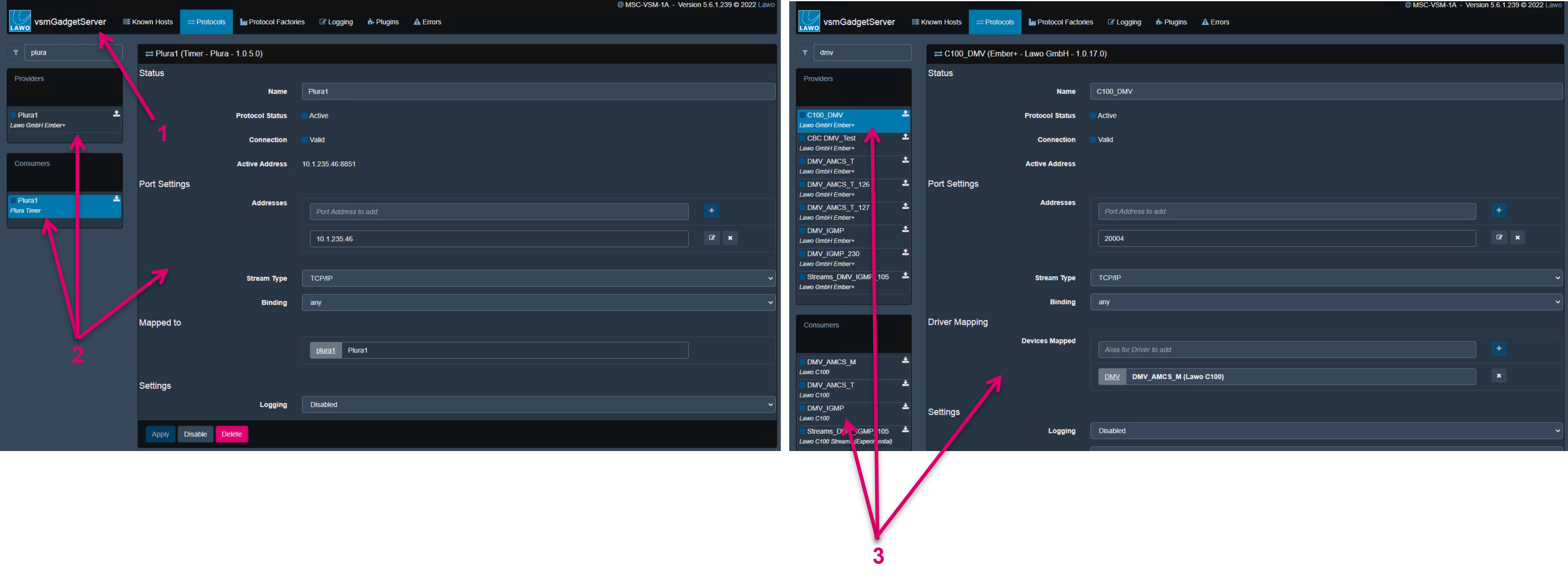
Both, Plura Timer and C100 vmDMV are interfaced via vsmGadgetServer (1).
Set up the respective Consumer and Provider ports for Plura Timer (2) and DMV (3).
DMV Parameters
After a valid communication with the DMV is established, all available Parameters are listed accordingly in the vsmStudio Gadget tree (1).

Plura Parameters
After a valid communication with the Plura System is established, all available Parameters are listed accordingly in the vsmStudio Gadget tree (1), and can be operated, e.g., via a vsmPanel (2).
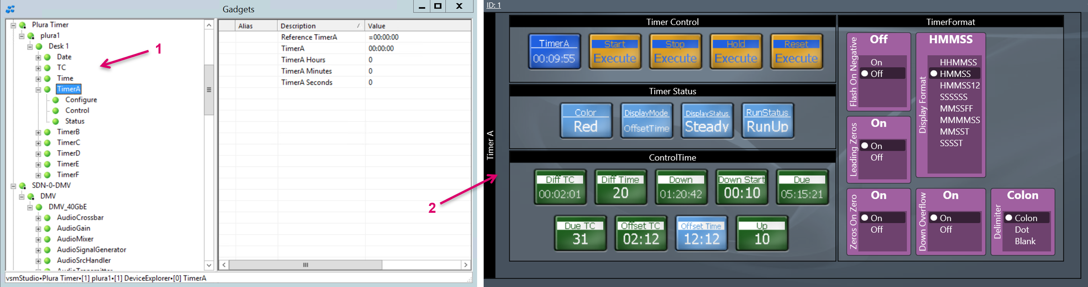
Since the common, required workflow is to use the dedicated Plura Numpad hardware as operational interface, VSM must forward respective parameter values and actions from one device to the other. While parameters basically only need to be linked, some actions require a little logic in between.
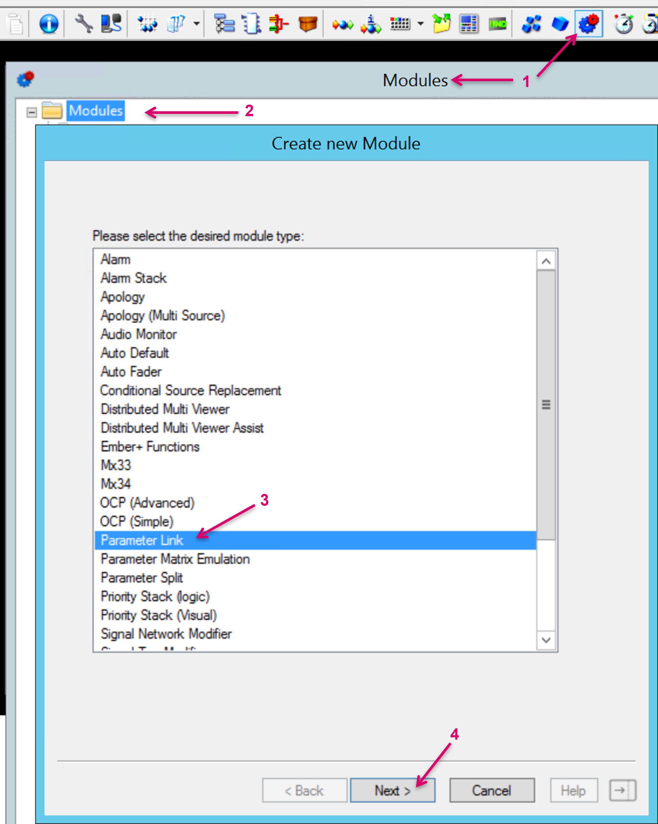
Hours, Minutes, Seconds via Parameter Link
To link the required time parameters, first create a Parameter Link module in vsmStudio. Open the Modules window via the respective icon on the vsmStudio toolbar (1). Right click on folder Modules (2) and select the Parameter Link module from the list (3). Proceed with Next (4).
After entering a Module Name (1), open in addition the Gadget tree of Plura and DMV to drag drop parameters into the drop zones within the Parameter Link module. Plura parameters represent Sources (2), and DMV parameters represent Targets (3). Confirm the module setup with Finish or OK (4). As a result, the module Target values will now “follow”
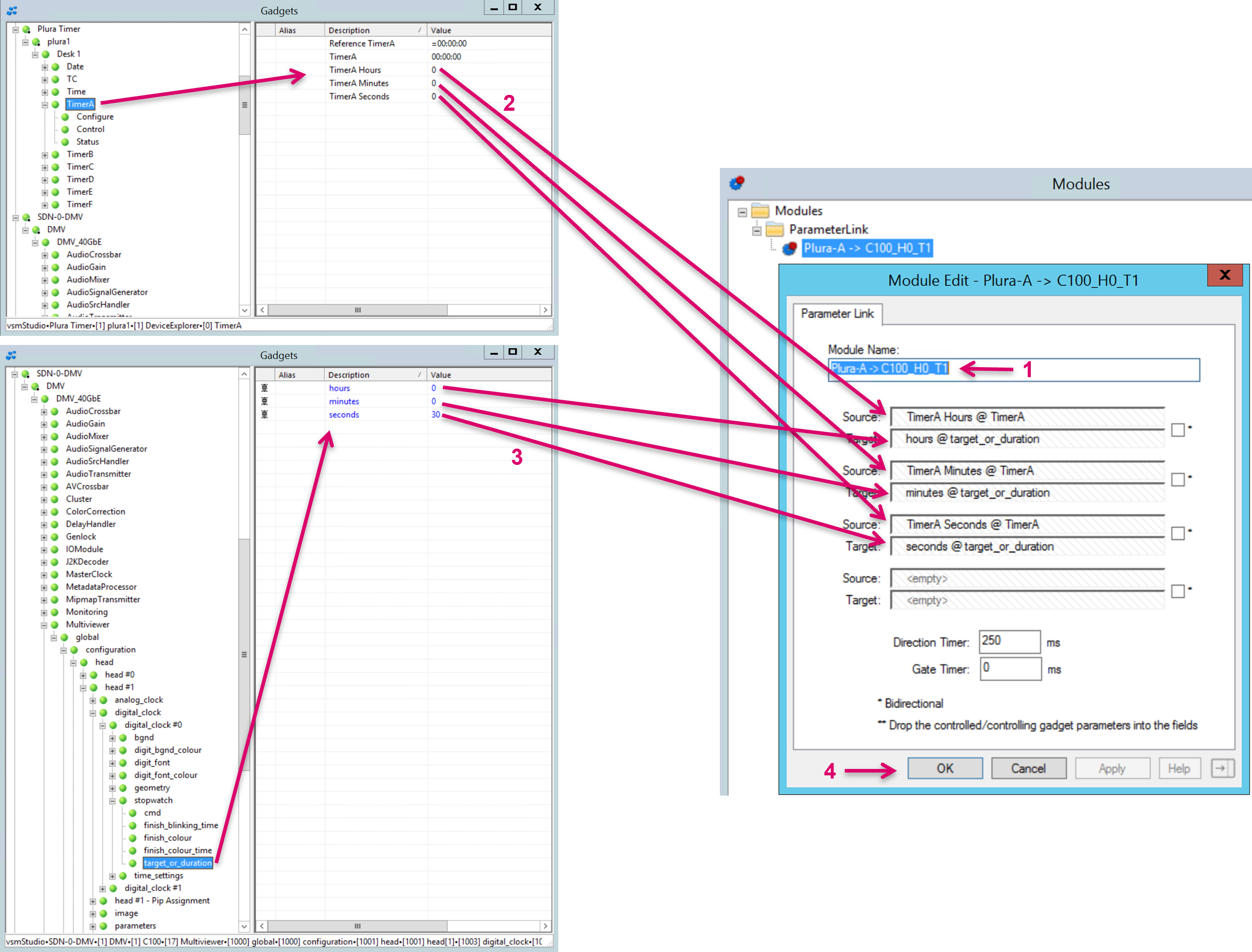
The same configuration approach may be used to link and forward any similar parameter values of same type.
Start, Stop, Pause, etc. via GPIO Logic
To forward navigation parameters like for instance Start, Stop, Count Up, Count Down, etc. it requires a level of translation in form of a GPO logic within vsmStudio. This is because source and target parameter values are different and cannot be simply linked. Therefore, a GPO calculation based on Plura status is used to then trigger the respective DMV commands. The configuration for some of the most often used commands is described in the following.
First open the GPI window via the icon on the vsmStudio toolbar.

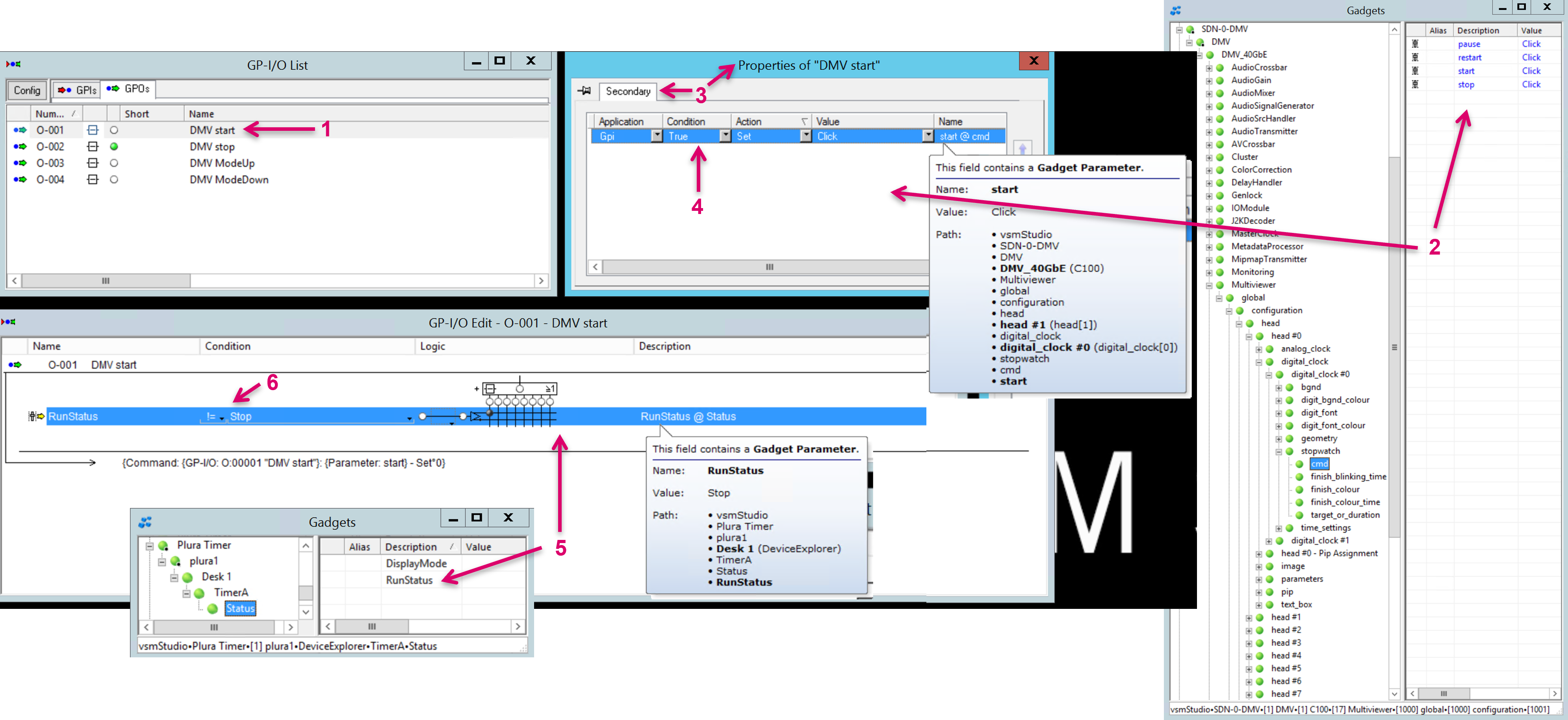
Start via GPIO Logic
On the GPO tab, create a GPO for the Start command (1).
Select and open this GPO and drag & drop the DMV stopwatch start parameter (2) into the secondary properties of the GPO (3). Set the Condition to True (4).
Drag & drop the Plura RunStatus parameter into the GPO Condition field (5). Set the Condition values to != and Stop (6).
Stop via GPIO Logic
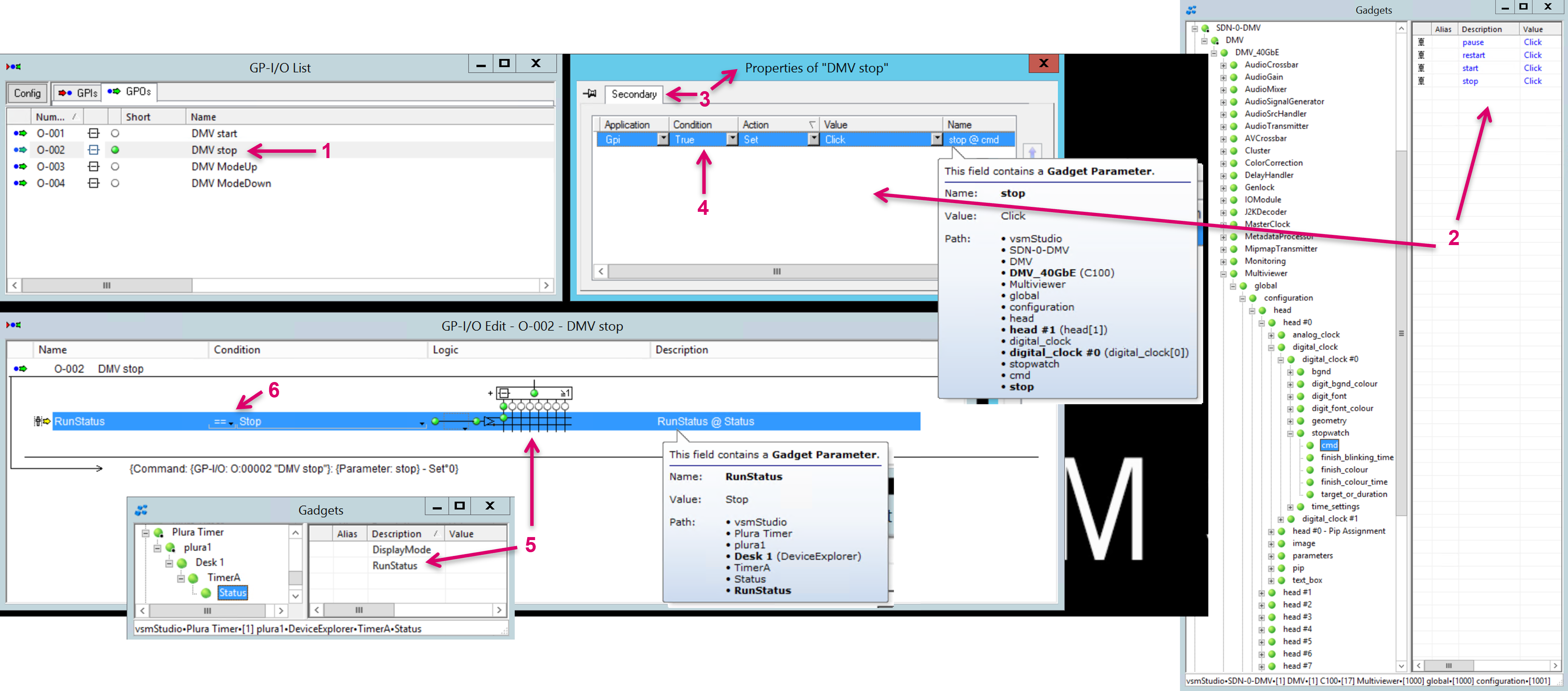
On the GPO tab, create a GPO for the Stop command (1).
Select and open this GPO and drag & drop the DMV stopwatch stop parameter (2) into the secondary properties of the GPO (3). Set the Condition to True (4).
Drag & drop the Plura RunStatus parameter into the GPO Condition field (5). Set the Condition values to == and Stop (6).
Count ModeUp via GPIO Logic
On the GPO tab, create a GPO for the ModeUp command (1).
Select and open this GPO and drag & drop the DMV stopwatch mode parameter (2) into the secondary properties of the GPO (3). Set the Condition to True (4). In the Value column select COUNT_UP_DURATION from the drop-down menu (5).
Drag & drop the Plura DisplayMode parameter into the GPO Condition field (6). Set the Condition values to == and Up (7).

Count ModeDown via GPIO Logic
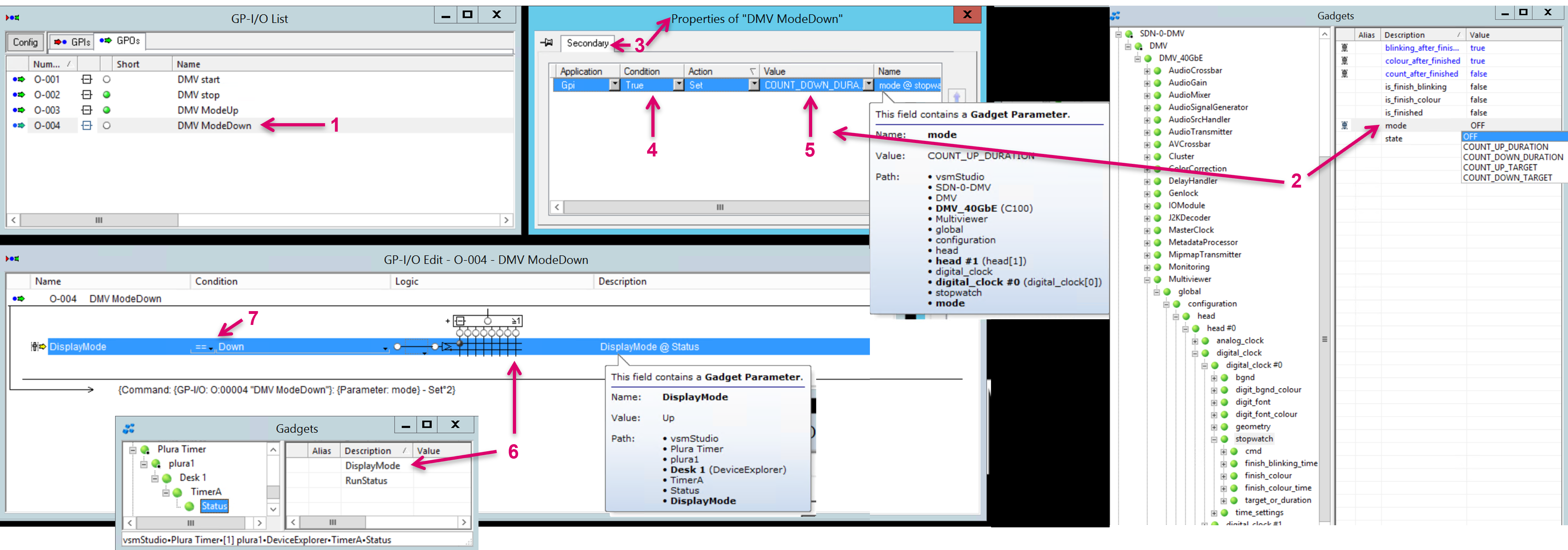
On the GPO tab, create a GPO for the ModeDown command (1).
Select and open this GPO and drag & drop the DMV stopwatch mode parameter (2) into the secondary properties of the GPO (3). Set the Condition to True (4). In the Value column select COUNT_DOWN_DURATION from the drop-down menu (5).
Drag & drop the Plura DisplayMode parameter into the GPO Condition field (6). Set the Condition values to == and Down (7).
The same configuration approach may be used to translate and forward any similar parameter values of different type.