Interface - theWall
This chapter covers the interface to theWall.
Based on:
- vsmStudio 22.1.1 [Build: 2360] release
- theWall 4.6.2110.27001
- vm_DMV 1.11.3762
Contents:
Introduction
In a Lawo multiviewer system solution, theWall represents the layout builder tool. theWall provides a smart and intuitive frontend GUI to easily create custom monitor wall layouts.
While theWall talks directly to the DMV to modify geometry and select visual elements to be displayed, in the overall broadcast system a broadcast controller is usually the master of routing, tally status and label information. Therefore, to provide a functioning overall system solution, a deep integration between both, respectively all three, systems is key.
This document describes the integration with focus on theWall application with vsmStudio, separated in three functional blocks, Routing, Label, Layout Recalls and a special section for the integration with the vsmStudio Distributed Multi Viewer module. The following descriptions assume that vsmStudio already has a working interface to the DMV and that theWall internal basic configuration (number of Monitors, Heads, etc.), based on the DMV cluster size was also done.
Overview of required control protocol port connections
- theWall routing via vLayer in vsmStudio - pro-bel SW-P-08 (Inbound vsmStudio)
- Label transfer from vsmStudio to theWall - Harris Image Video (Outbound vsmStudio)
- vsmStudio recall Files in theWall - Ember+ (Outbound vsmStudio)
- Head to Monitor assignment status from vsmStudio to theWall - pro-bel SW-P-08 (Inbound vsmStudio)
theWall routing via vsmStudio – Setup router in theWall
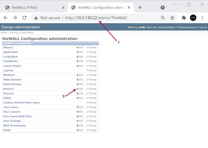
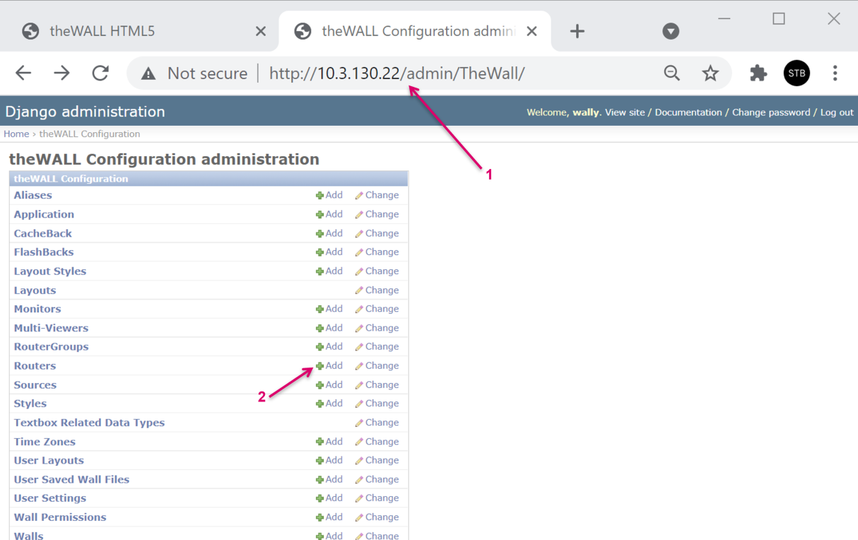
Navigate to the configuration backend of the wall via http://>theWallServerIP</admin.
On the Line-item Router, click Add.
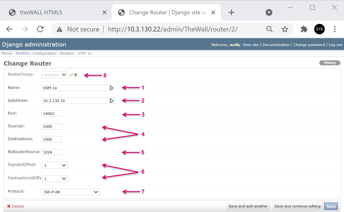
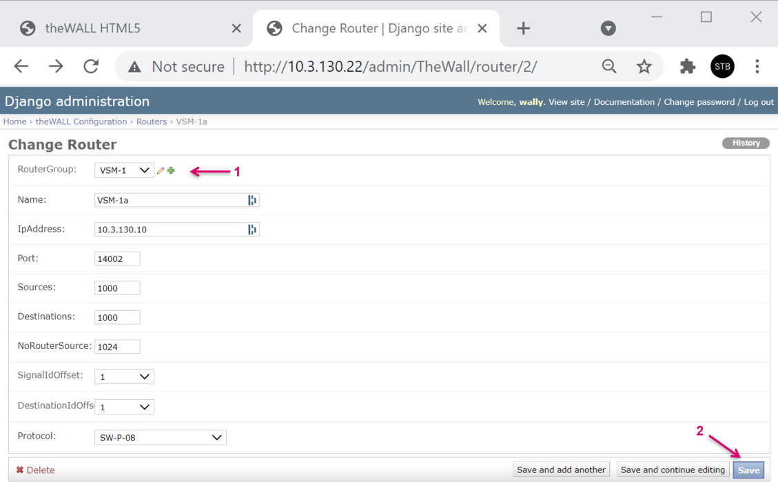
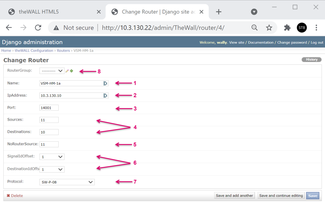
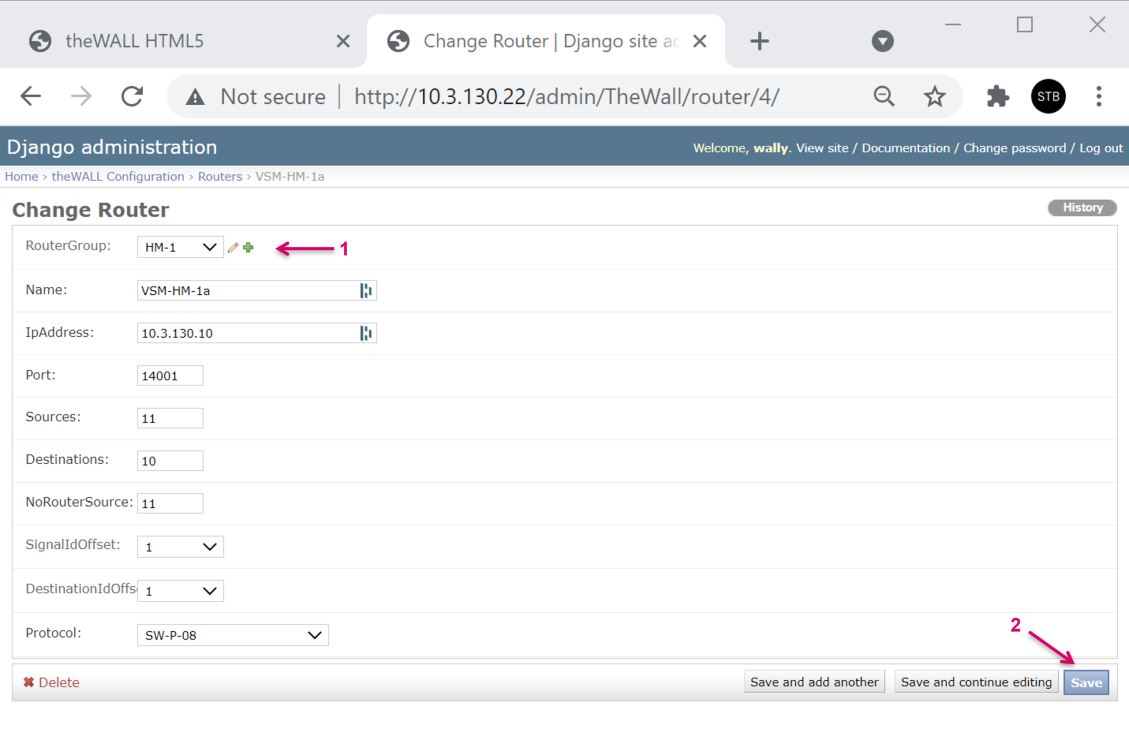
Set a Name (1) and the IPAddress (2) for the Router, represented by the vsmStudio vLayer.
Define a Port (3) number, that needs to match the Port number set in vsmStudio. Define the number of Sources and Destinations (4) that should match the router/ vLayer size in vsmStudio.
Define the position (matrix ID) for a NoRouterSource (5) that effectively would be the Blind/ Disconnect Source in vsmStudio. Define the SignalIDOffsets (6).
These offsets are set to 1 in the case of vsmStudio being the router, since the first position on the vLayer is ID 1. Select the Protocol (7) used for this connection, in this case SW-P-08.
If the router has a redundant setup, a RouterGroup must be created and set.
To proceed click the + Symbol (8).
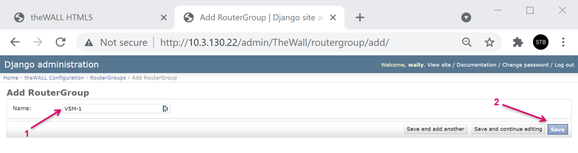
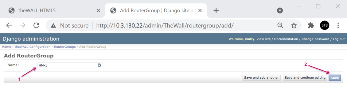
In the opening window set a Name (1) for the RouterGroup and confirm with Save (2).
Select the RouterGroup (1) in the Routers configuration and finish this Router setup with Save (2).
theWall routing via vsmStudio – Map router in theWall
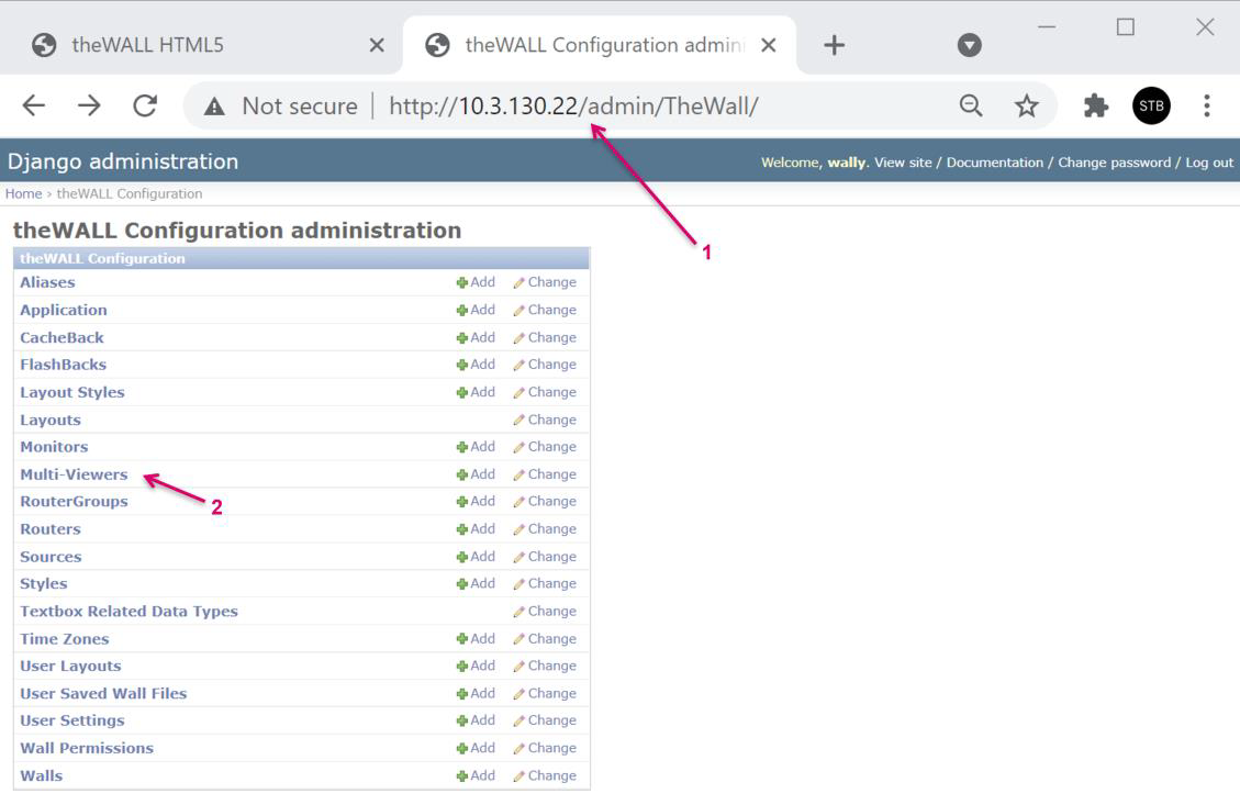
Return to the main menu of theWall configuration (1).
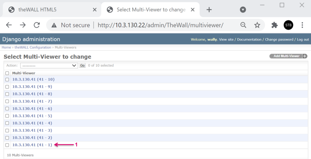
As mentioned in the Introduction we assume the basic configuration in theWall done beforehand. This means also that Multi-viewer instances were already created. Click on Multi-Viewers (2).

Select the Multi-Viewer (effectively physical DMV Head) to be modified.
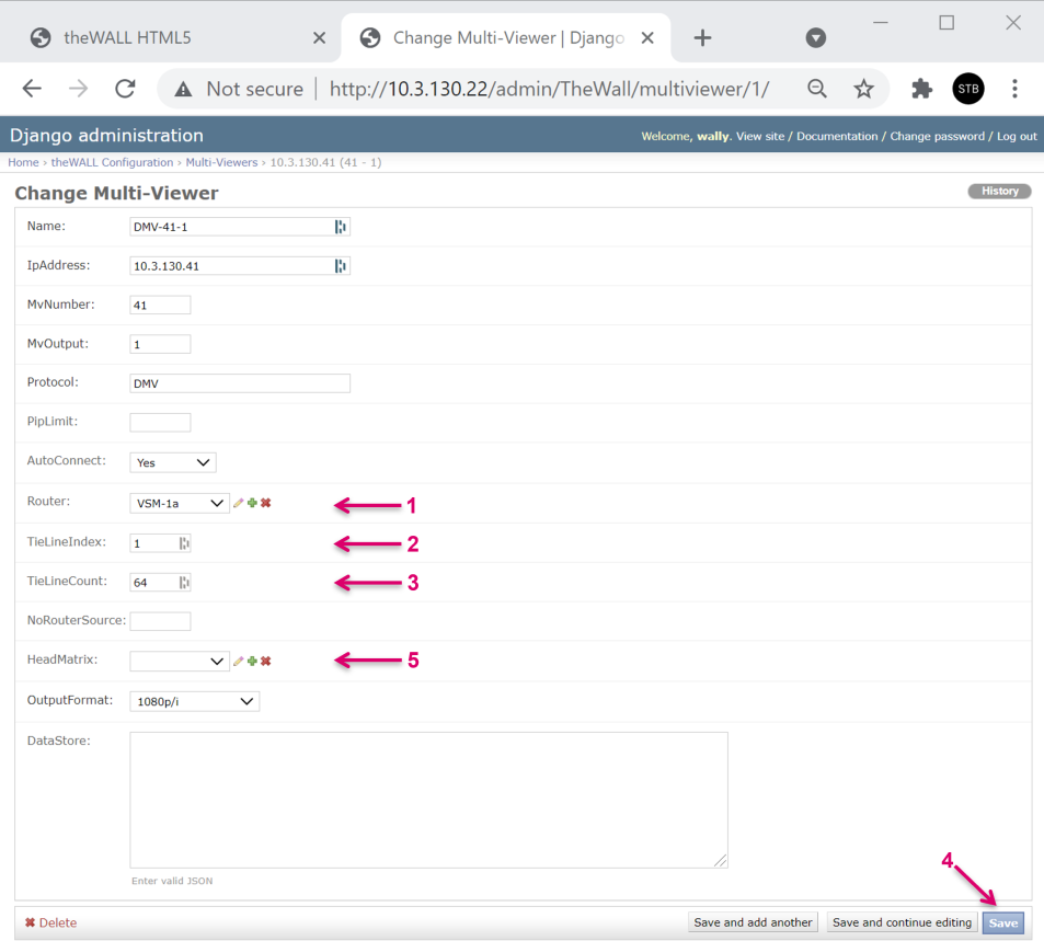
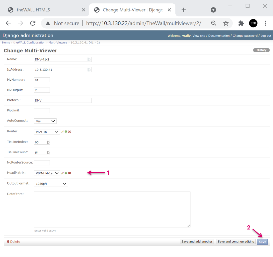
Assign the Router (1) that provides the Sources and respecting PIP target references.
You can only select a single Router, no RouterGroups. Still, if the assigned Router is part of a RouterGroup, theWall will effectively connect to all Routers of that Group.
The TieLineIndex (2) defines the Router ID with the first PIP, of the respective Multiviewer Head. The TieLineCount (3) defines the range of PIPs/ IDs for the respective Multiviewer Head. Finish the configuration with Save (4).
The assignment of a HeadMatrix (5) comes into play if the Distributed Multi Viewer module in vsmStudio is used. Please refer to the respective chapter in this document.
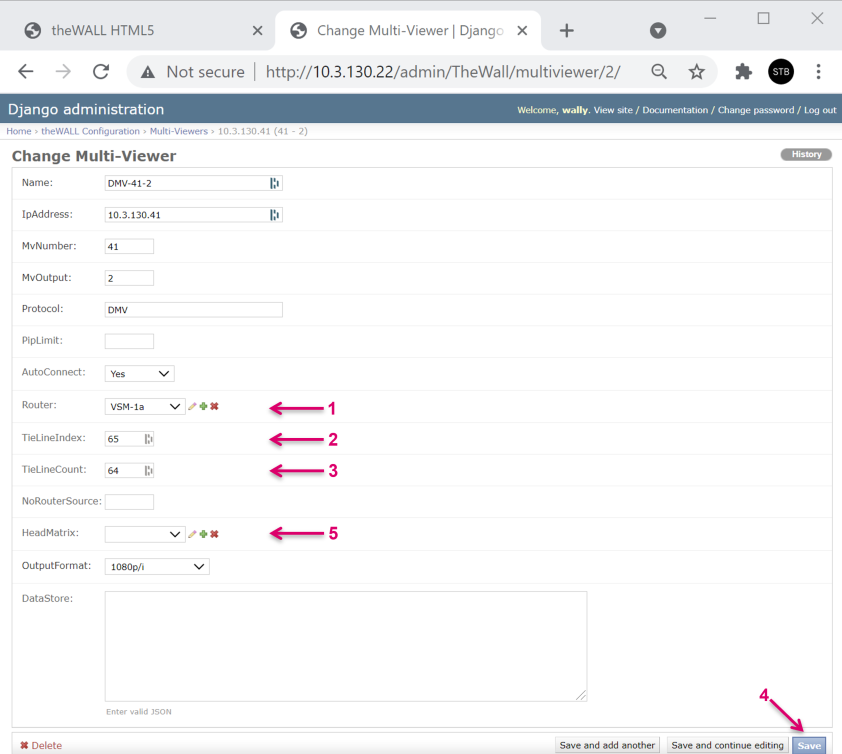
Here the look into the configuration of the second Multi-Viewer, as another example for the required settings. In the example, the PIP count per Head is 64 PIPs.
TieLineIndex and TieLineCount need to match the actual Router configuration (vLayer assignment).
theWall routing via vsmStudio – Set up vLayer in vsmStudio
As a first step we create a vLayer that later can be mapped to the control port connection for theWall. Always keep in mind that in the end, vLayer configuration in vsmStudio and Router setup in theWall must match.
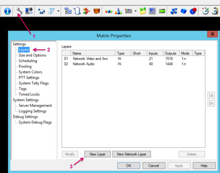
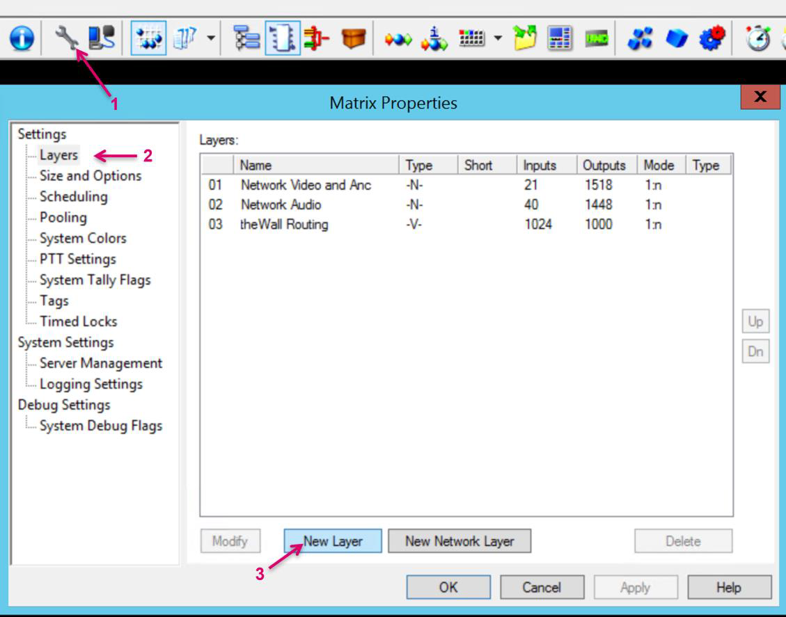
Navigate to Matrix Properties via the vsmStudiotoolbar (1). Select the Layers section (2) and click on New Layer (3).
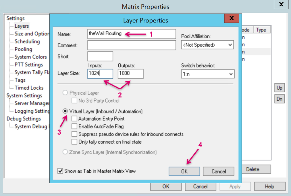
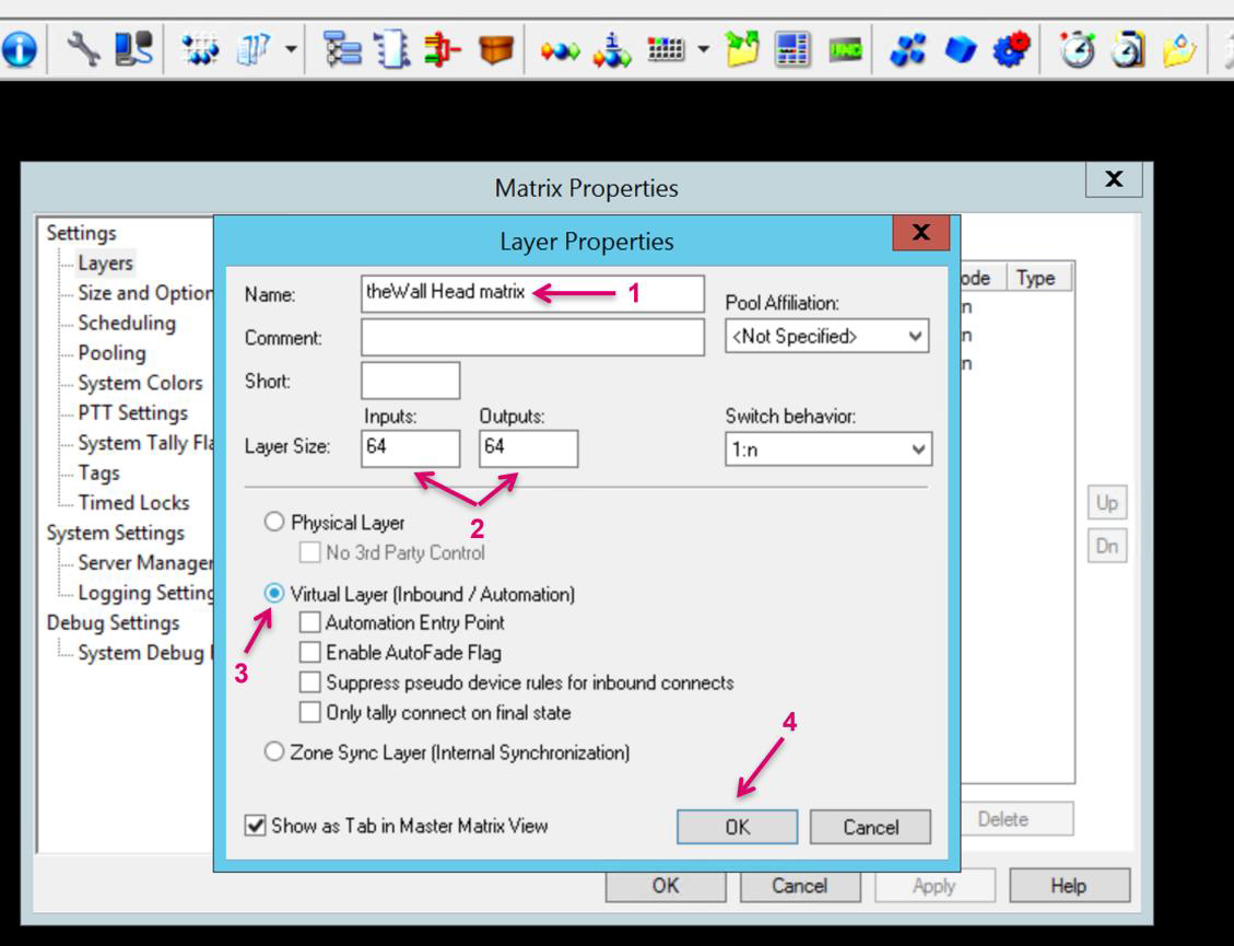
Set a Name for the layer (1). Define the Layer Size (2). Select Virtual Layer (3) and confirm with OK (4).
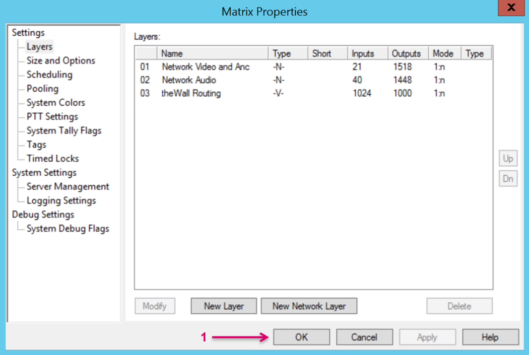
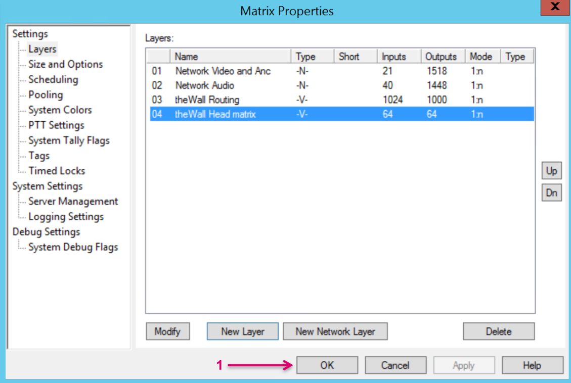
Finish the Layer setup with OK (1).
In the next step we will assign source and target Signalpaths to the vlayer.
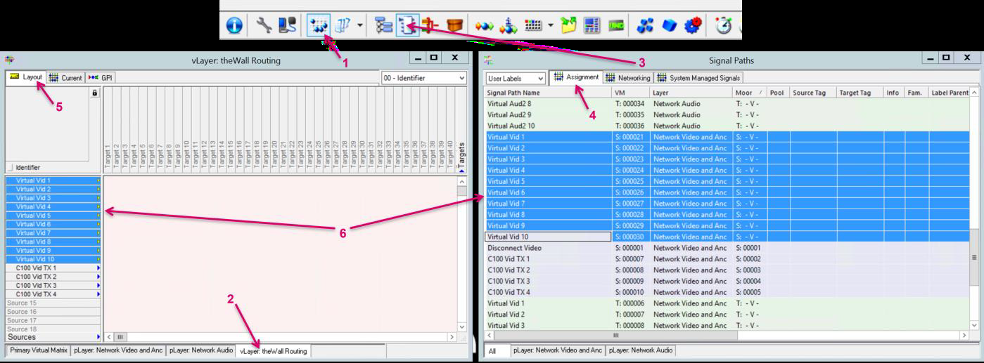
Open the Matrix View from the vsmStudio toolbar (1) and navigate to the vLayer tab (2).
In parallel open the Signal Paths list from the vsmStudio toolbar (3) and select the Assignment tab (4).
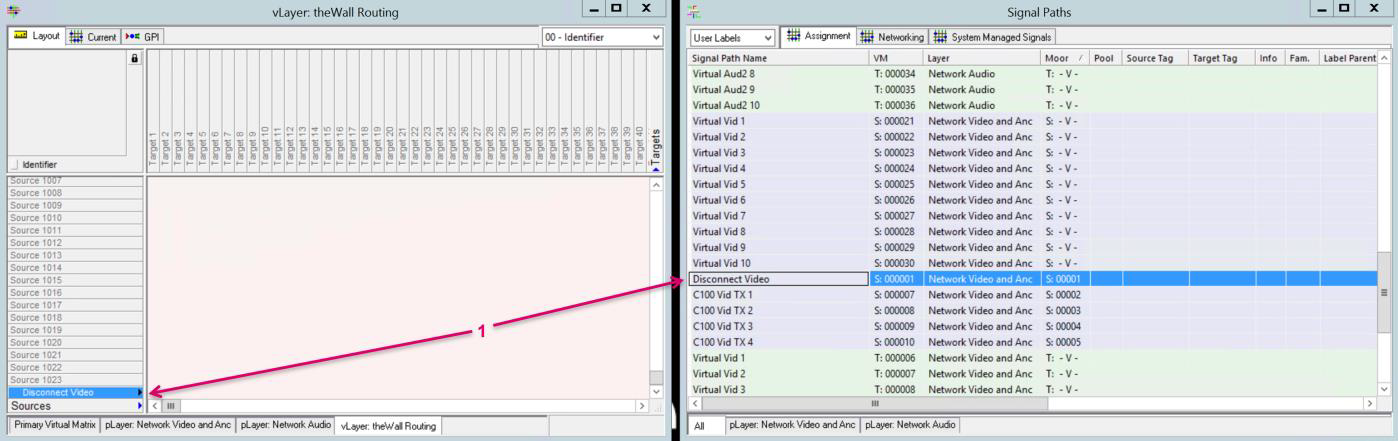
Make sure you are on the Layout tab (5) in the matrix view, then select and drag&drop the Sources, that theWall should be able to access, on the Sources section on the vLayer (6).
Drag&drop the Disconnect/Blind source on the ID which was defined as NoRouterSource in the Router configuration of theWall.
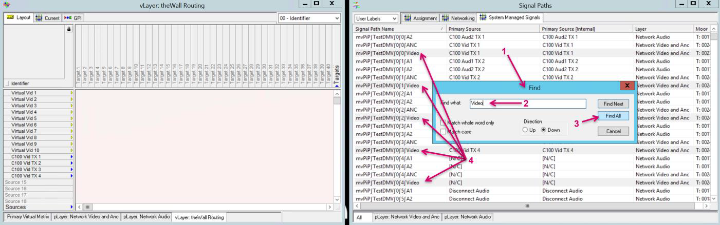
In the Signal Paths list open the tab System Managed Signals (1). Since we want to select only the Video leg of the PIP targets from this list and want to avoid a click-by-click operation, we can utilize the Search function. Open Search by pressing F3 on the keyboard. Enter Video under Find what (2). Click Find All (3). All Signalpaths with Video in the label will get selected (4).
Since we only want to pick PIP Video Signalpaths, deselect the mvTarget Signalpaths by holding Ctrl. Key, select first mvTarget, in addition hold Shift key and click last mvTarget (1). Afterwards drag&drop the Targets, on the Targets section on the vLayer (2).
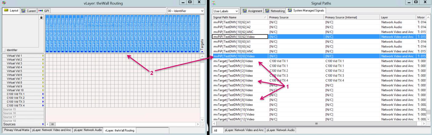
Note: vsmStudio will create 64 mvPIP (System Managed Signal) targets per Head. If using the Find All selection, obviously all will be selected accordingly. In case it is desired to expose a smaller PIP range per Head towards theWall, you may need to choose a different selection approach.
theWall routing via vsmStudio – Set up the communication port in vsmStudio
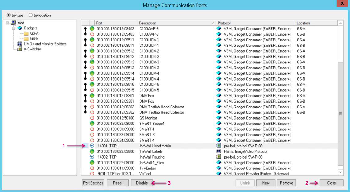
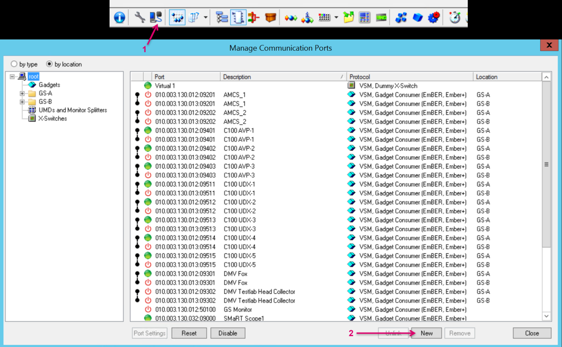
Next step is to set up the communication to theWall Server. For the routing part we need an inbound SW-P-08 protocol port. Navigate to Manage Communication Ports via the vsmStudio toolbar (1). Click New (2).

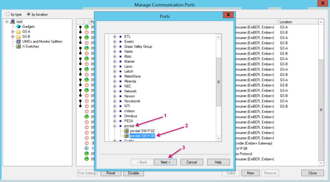
In the opening Ports window navigate to pro-bel (1) and select pro-bel SW-P-08 (2). Confirm with Next (3).
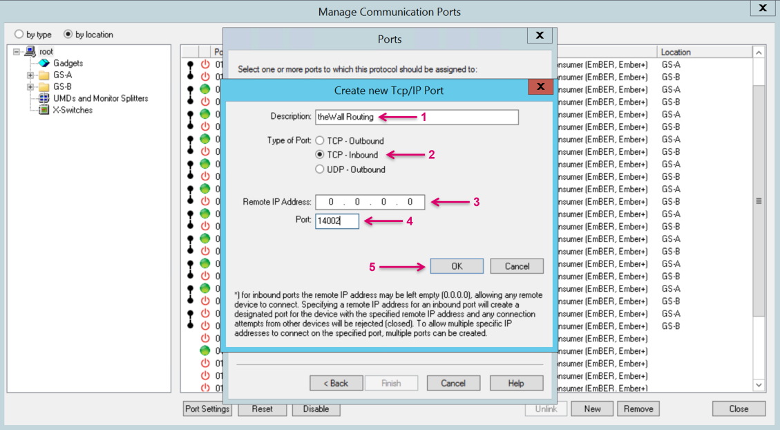
Proceed by clicking New Port (1).

Assign a Description name for the connector (1). Set the Type of Port to TCP-Inbound (2). We can leave the Remote IP Address set to the default 0.0.0.0 (3).
The Port number (4) must be set according to the setting in theWall Router configuration. Confirm with OK (5).
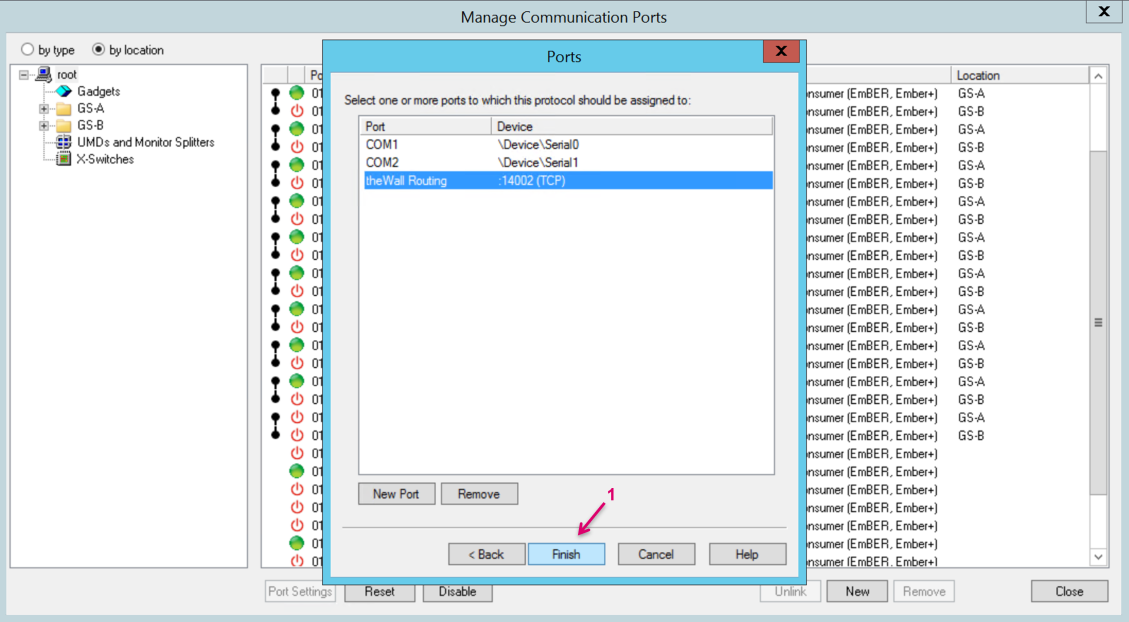
Proceed the setup by clicking Finish (1).
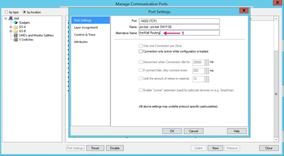
In the Port Settings window add an Alternative Name (1) for a clearer display in the Manage Communication Ports view. This may be just the same as used for Description Name before.
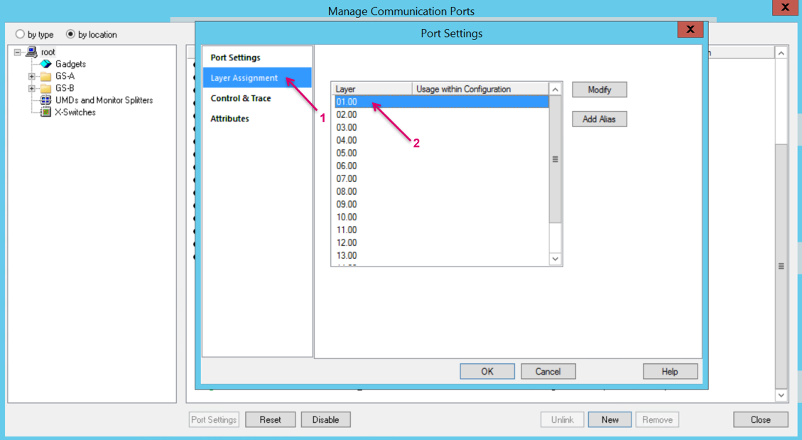
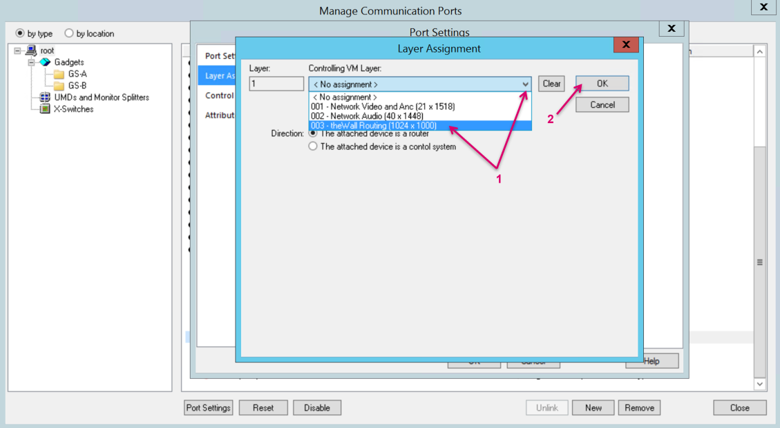
Select Layer Assignment (1) from the menu bar. Double-click on Layer 01.00 (2).
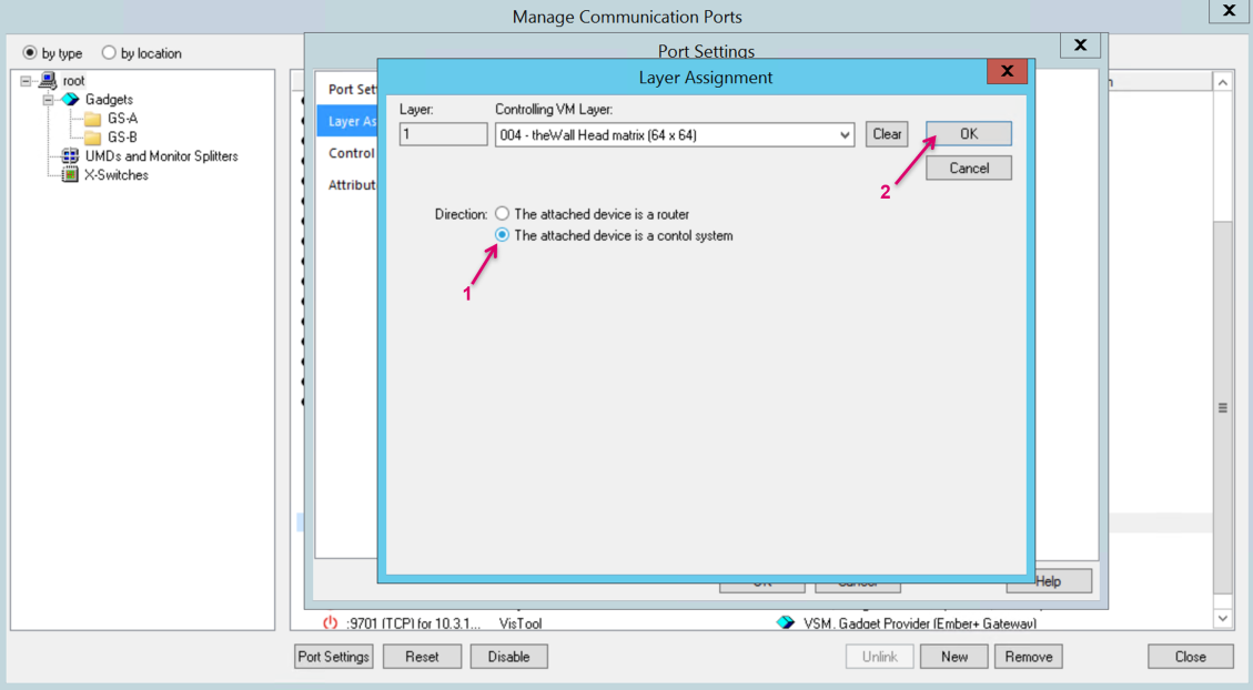
To map the vLayer to the communication port, select the Controlling VM Layer from the drop-down menu (1). Confirm with OK (2).
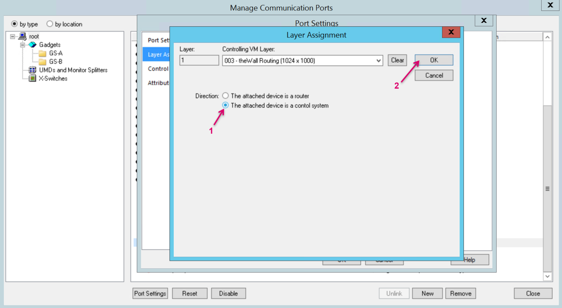
Set the port Direction to The attached device is a control system (1). Confirm with OK (2).
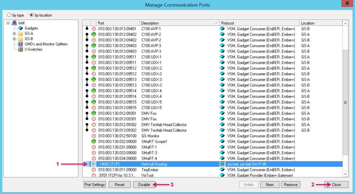
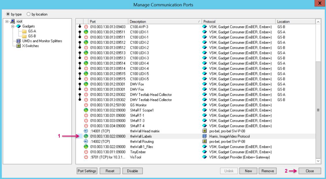
The port setup is now complete, and the port is listed in the Manage Communication Ports view (1). Unless you need to set up another control port you can Close the window (2).
An Inbound connection shows no active communication status. Also, in case you need to reset an Inbound port on vsmStudio side, use the Disable/ Enable control (3) instead of Reset.
Label transfer from vsmStudio to theWall – Set up in vsmStudio
The Source label transfer does not require any setup on theWall side. Once a valid protocol connection is established from vsmStudio side, theWall will receive Labels and display them accordingly in the Source selection bar on theWall UI. Label IDs are in fixed 1:1 relation to the Router created and assign to Multiviewers in theWall configuration.
To set up the communication port on vsmStudio side, navigate to Manage Communication Ports via the vsmStudio toolbar (1). Click New (2).

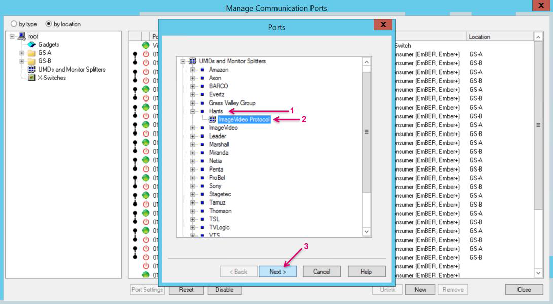
In the opening Ports window navigate to Harris (1) and select ImageVideo Protocol (2). Confirm with Next (3).
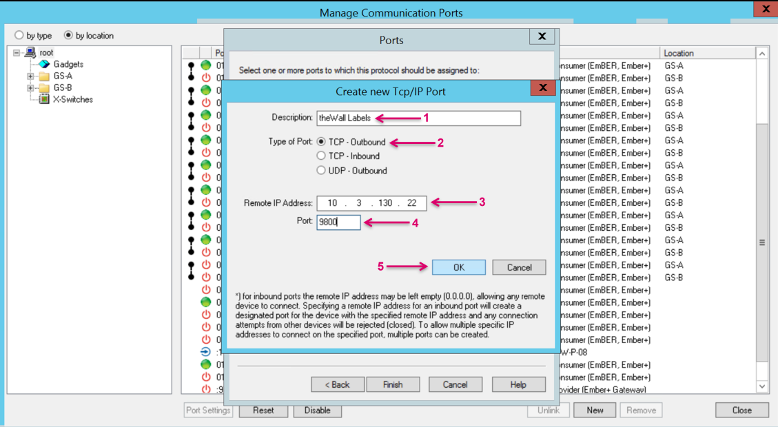
Proceed by clicking New Port (1).

Assign a Description name for the connector (1). Leave/ set the Type of Port to the default TCP-Outbound (2). Enter theWall Server IP under Remote IP Address (3).
Set the Port number to 9800 (4). Confirm with OK (5).
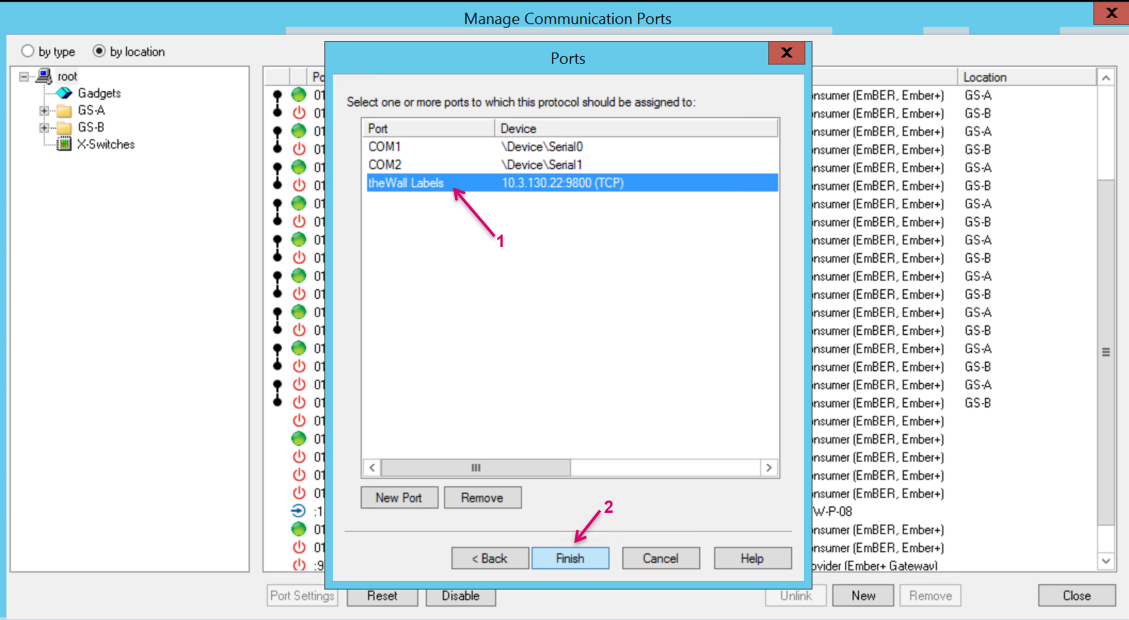
Proceed the setup of the communication port (1) by clicking Finish (2).
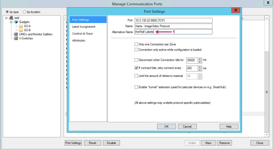
In the Port Settings window add an Alternative Name (1) for a clearer display in the Manage Communication Ports view. This may be just the same as used for Description Name before.
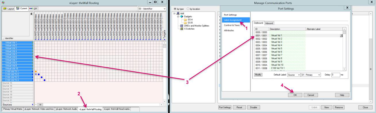
Select Layer Assignment (1) from the menu bar. Open the vsmStudio matrix Master View, navigate to the tab representing the vLayer for theWall routing (2). Select Source Signals in the matrix view and drag&drop them on the Description fields of the corresponding IDs in the Port Settings view (3).
The source IDs in vsmStudio are ID 1-based. In theWall Router configuration process, explained in one of the chapters above, we did set the SourceIdOffset to 1 accordingly. To match the Labels accordingly we skip ID 000 in the Label Assignment as well and start with 001.
The port setup is now complete, and the port is listed in the Manage Communication Ports view (1). Unless you need to set up another control port you can Close the window (2).
File Recall in theWall via vsmStudio – Files in theWall
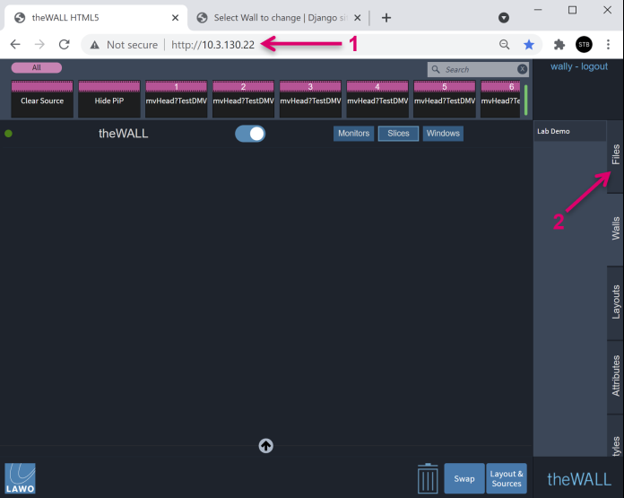
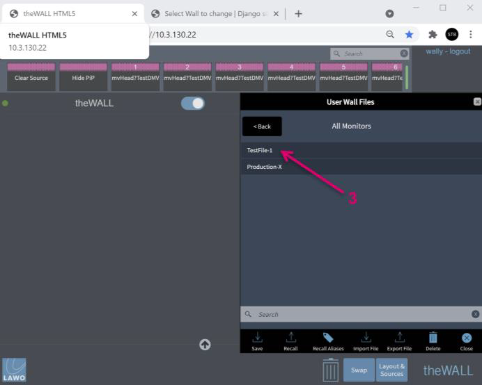
theWall allows File recalls triggered from external via an Ember+ protocol connection. Navigate via webBrowser to theWall UI by entering the respecting IP address (1). Open the Files tab (2) from the righthand toolbar. Here you can Save and Recall User Wall Files. (3)
Consider that the recall via protocol is name-based. Informative File names may be helpful for further configuration and operation.
By design, theWall Files are wall-based. If a wall setup in theWall consists of multiple monitors, it is not possible to directly recall settings per one specific monitor. If it is desired to trigger recalls per single monitors, it would require creating a wall per monitor in theWall configuration and save Files accordingly.
By design, theWall Files include layout and source to PIP routing status.
Still, it is possible via two separate Ember+ Parameters to recall Files either with layout with PIP routing or layout only without PIP routing. Nothing special to do when executing Save inside in theWall. The File name triggered is the same, based on which Parameter Value is received, the File will be just handled and executed differently in theWall.
File Recall in theWall via vsmStudio – Set up in vsmStudio
The File recall does not require any specific setup on theWall side. Once a valid protocol connection is established from vsmStudio side, vsmStudio can recall Files that were saved via theWall GUI and that are stored on theWall Server. The File recall is name-based.
To set up the communication port on vsmStudio side, navigate to Manage Communication Ports via the vsmStudio toolbar (1). Click New (2).
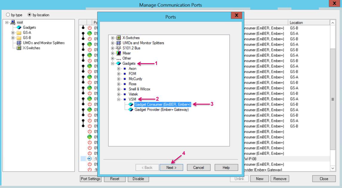
In the opening Ports window navigate to Gadgets (1), VSM (2)
and select Gadget Consumer (EmBER, Ember+) (3). Confirm with Next (4).
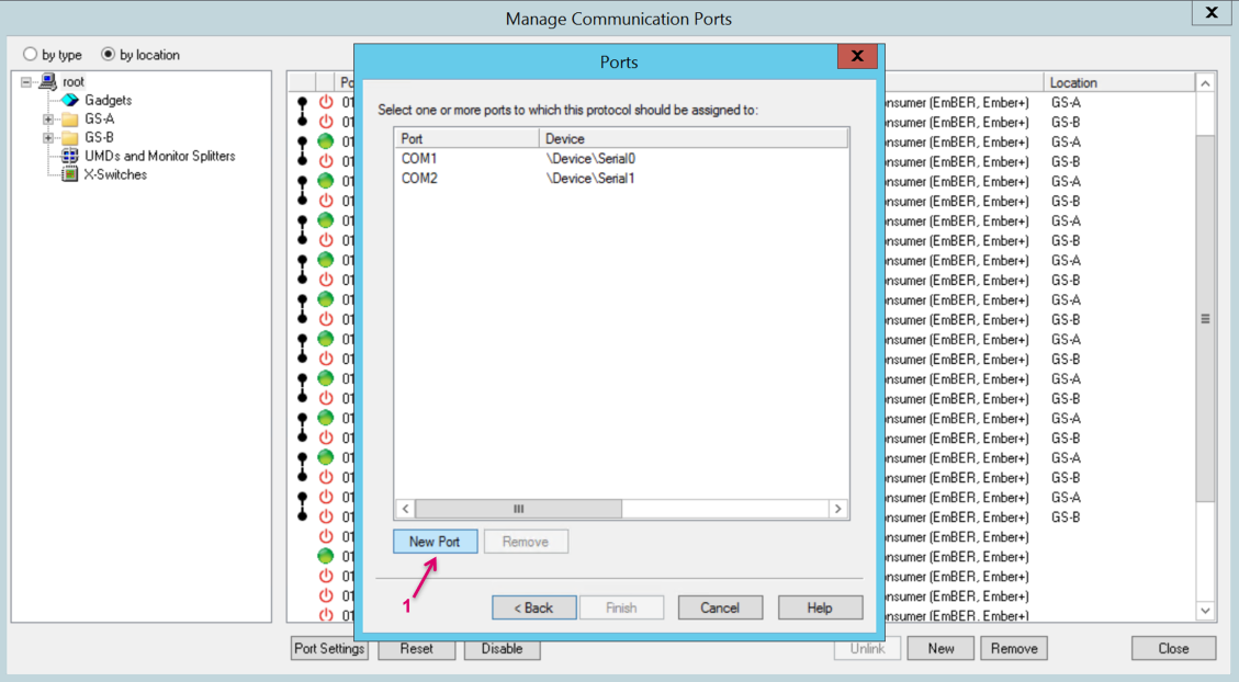
Proceed by clicking New Port (1).
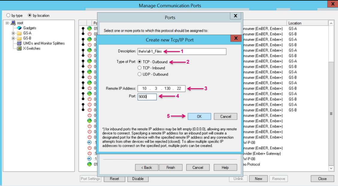
Assign a Description name for the connector (1). Leave/ set the Type of Port to the default TCP-Outbound (2). Enter theWall Server IP under Remote IP Address (3).
Set the Port number to 9000 (4). Confirm with OK (5).
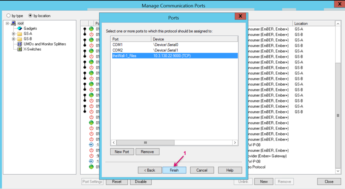
Proceed the setup of the communication port (1) by clicking Finish (2).
In the Port Settings window add an Alternative Name (1) for a clearer display in the Manage Communication Ports view. This may be just the same as used for Description Name before.
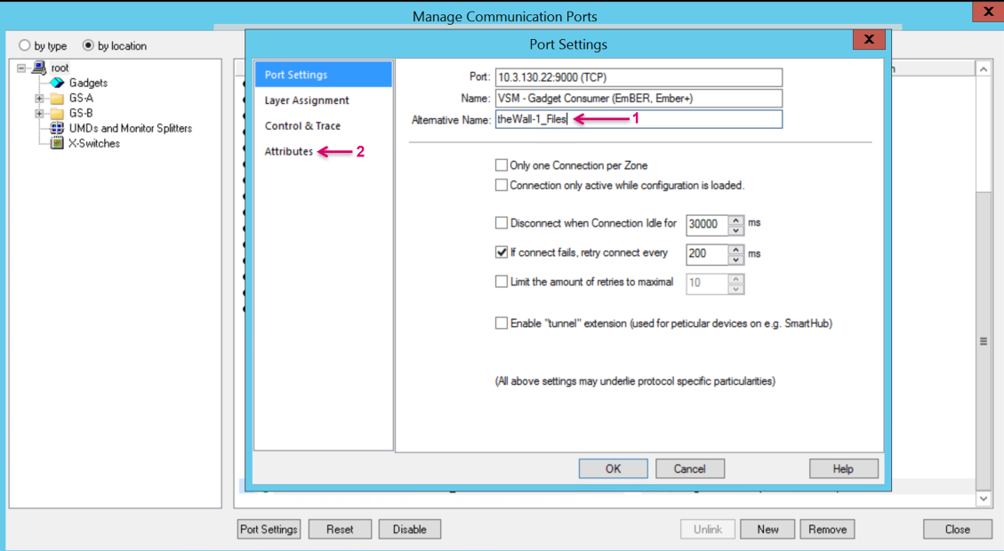
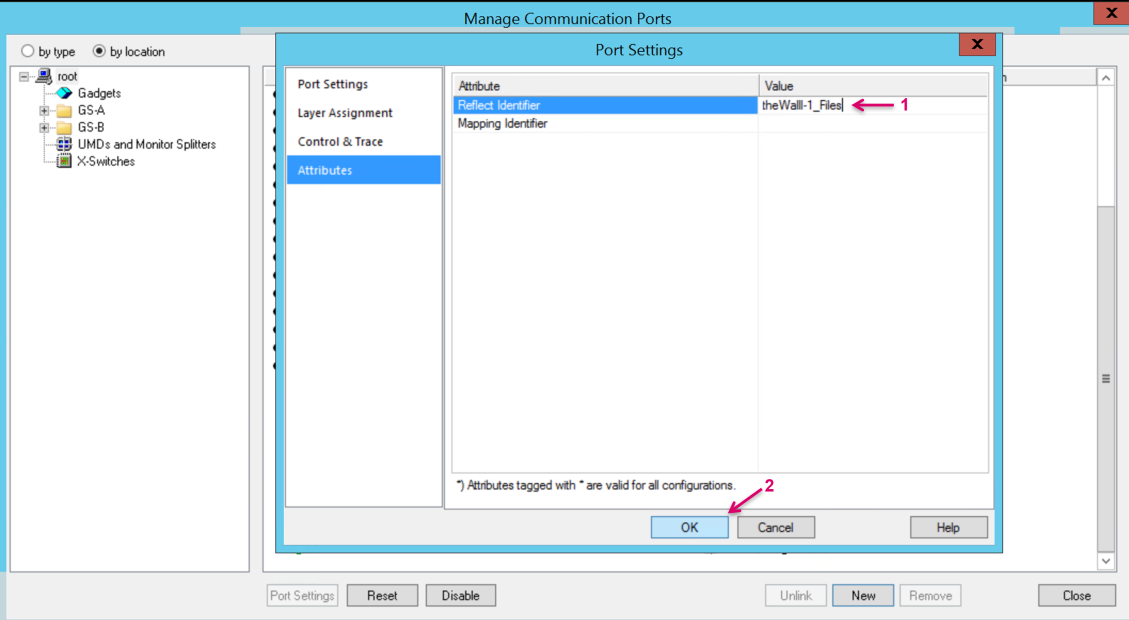
Select Attributes from the menu bar and set an identifier name in the Value Field in the row Reflect Identifier (1). This Reflect Identifier name represents a static Gadget Tree node and reference pathway to underlying Parameters even if the respecting Gadget tree needs to be mapped to different Communication Port Settings.
Confirm with OK (2).
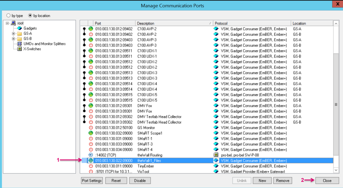
The port setup is now complete, and the port is listed in the Manage Communication Ports view (1). Unless you need to set up another control port you can Close the window (2).
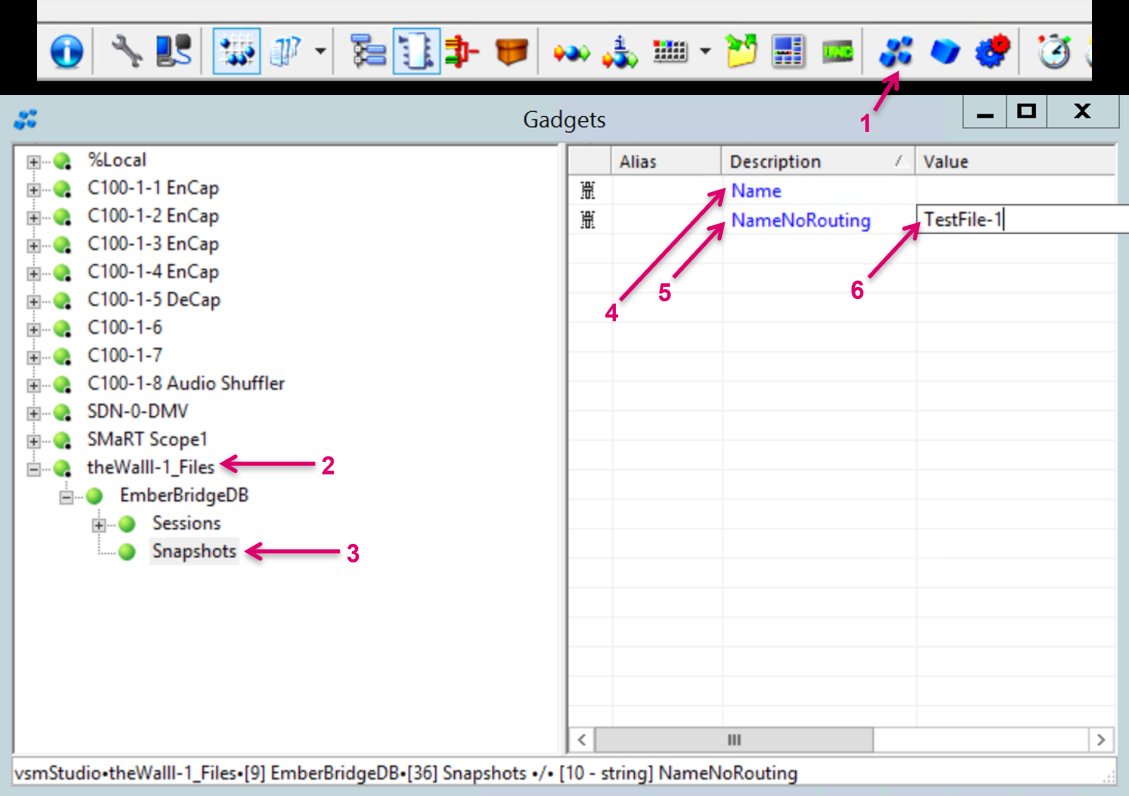
Once the communication is successfully established, all Parameters exposed by the attached device are listed in Gadgets (1) under the Reflect Identifier node (2). In the tree navigate to sub-node Snapshots (3). In the right-hand part of the Gadgets view, two Parameters are exposed by theWall.
Entering the name of an existing theWall File in exact writing (6) in the Value field Name (4), followed by enter on the computer keyboard, will recall the respecting File in full, including Layout and Routing.
Entering the same name in the Value field NameNoRouting (5), followed by enter on the computer keyboard, will recall the respecting File as well but Layout only. The recall happens immediately after pressing Enter on the computer keyboard.
The trigger is sent, and the recall is executed without any further notice and/ or status feedback towards vsmStudio.
theWall HeadMatrix – Setup router in theWall
In combination with the Distributed Multi Viewer module in vsmStudio, an additional Router layer is required to read out the physical DMV Head to Monitor assignment. Reason for this is that the Distributed Multi Viewer module is handling physical Head resources as a pool, and this effectively means, no static relation between a Head number and a specific Monitor could be set up. Any Head could possibly be assigned to any Monitor at any time. By reading out the current assignment in form of crosspoint status via another vLayer in vsmStudio, theWall UI still can be used as usual while the system knows at any time which Head parameters must be addressed in the background.
To create the new router in theWall, navigate to the configuration backend of the wall via http://>theWallServerIP</admin.
On the Line-item Router, click Add.
Set a Name (1) and the IPAddress (2) for the Router, represented by the vsmStudio vLayer. Define a Port (3) number, that needs to match the Port number set in vsmStudio. Define the number of Sources and Destinations (4) that should match the router/ vLayer size in vsmStudio. Define the ID for a NoRouterSource (5).
In the case of the Head matrix the NoRouterSource does relate to a Probel protocol source message but not to an existing Blind Source on the vLayer matrix.
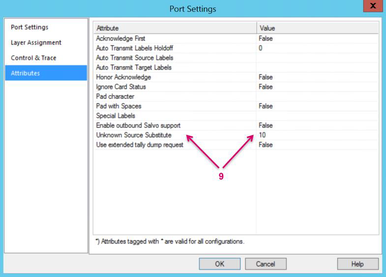
This ID is pre-defined on vsmStudio and theWall side to identify if a target is routed to anything else than one of the existing sources on the Head matrix, e.g., a direct Source got routed to the monitor instead of a Head output. On vsmStudio side the respecting ID is set in the Attributes tab of the Port Settings (9). Note there’s an offset of 1 on theWall side.
Define the SignalIDOffsets (6). These offsets are set to 1 in the case of vsmStudio being the router, since the first position on the vLayer is ID 1. Select the Protocol (7) used for this connection, in this case SW-P-08. If the router has a redundant setup, a RouterGroup must be created and set. To proceed click the + Symbol (8).
In the opening window set a Name (1) for the RouterGroup and confirm with Save (2).
Select the RouterGroup (1) in the Routers configuration and finish this Router setup with Save (2).
theWall HeadMatrix – Map router in theWall
To assign the just created Head Matrix Router as reference for each Multiviewer, return to the main menu of theWall configuration (1).
Click on Multi-Viewers (2).
Select the Multi-Viewer (effectively physical DMV Head) to be modified.

Assign the HeadMatrix (1). Finish the configuration with Save (2).
theWall HeadMatrix – Set up vLayer in vsmStudio
On the vsmStudio side we need to create a vLayer that provides the Head to Monitor assignment status. This vLayer will be mapped to a dedicated control port to theWall in a second step. Always keep in mind that in the end, vLayer configuration in vsmStudio and respecting Router setup in theWall must match.
Navigate to Matrix Properties via the vsmStudiotoolbar (1). Select the Layers section (2) and click on New Layer (3).
Set a Name for the layer (1). Define the Layer Size (2). Select Virtual Layer (3) and confirm with OK (4). Finish the Layer setup with OK (1).
Finish the Layer setup with OK (1).
In the next step we will assign source and target Signalpaths to the vlayer.
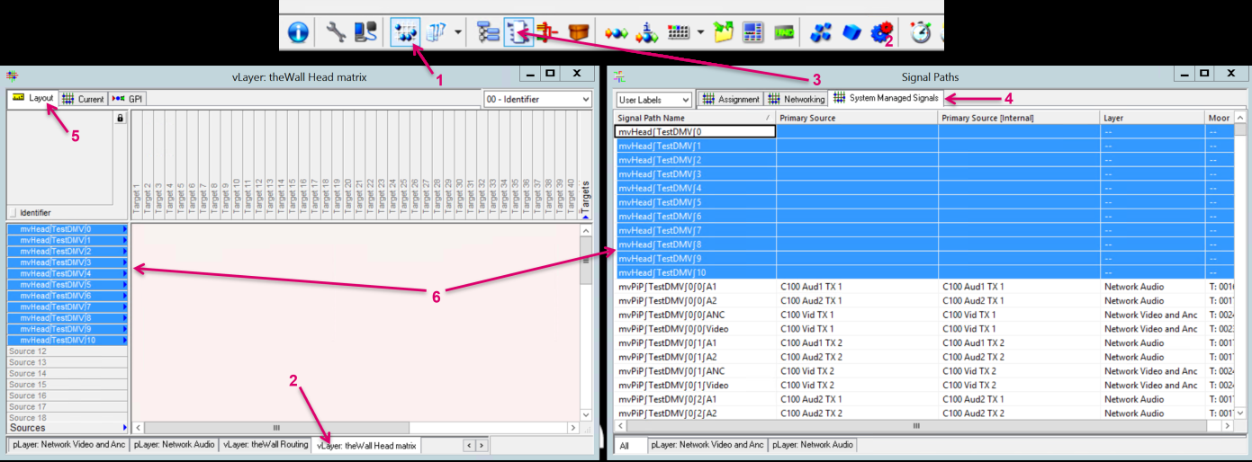
For the sources, open the Matrix View from the vsmStudio toolbar (1) and navigate to the vLayer tab (2).
In parallel open the Signal Paths list from the vsmStudio toolbar (3) and navigate to the System Managed Signals tab (4). Make sure you are on the Layout tab (5) in the matrix view, then select and drag&drop the mvHead Sources, that represent the physical Head outputs, on the Sources section on the vLayer (6).
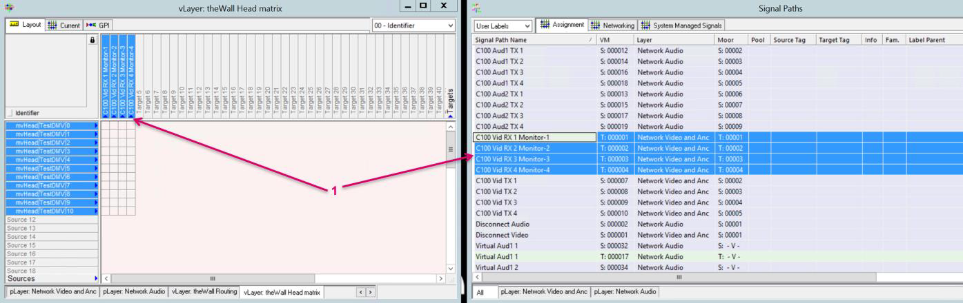
For the targets, open the Assignment or Networking tab in the Signal Paths list. Select the Monitor Targets that are represented as Monitors in theWall configuration.
This means the target dropped in the target position 01 on the vLayer, must match Monitor-01 in theWall configuration.
Drag&drop the Targets, on the Targets section on the vLayer (1).
theWall HeadMatrix – Set up the communication port in vsmStudio
Next step is to set up the communication to theWall Server. For the Head to Monitor routing status we need an inbound SW-P-08 protocol port. Navigate to Manage Communication Ports via the vsmStudio toolbar (1). Click New (2).

In the opening Ports window navigate to pro-bel (1) and select pro-bel SW-P-08 (2). Confirm with Next (3).

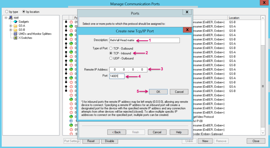
Proceed by clicking New Port (1).

Assign a Description name for the connector (1). Set the Type of Port to TCP-Inbound (2). We can leave the Remote IP Address set to the default 0.0.0.0 (3). The Port number (4) must be set according to the setting in theWall Router configuration. Confirm with OK (5).
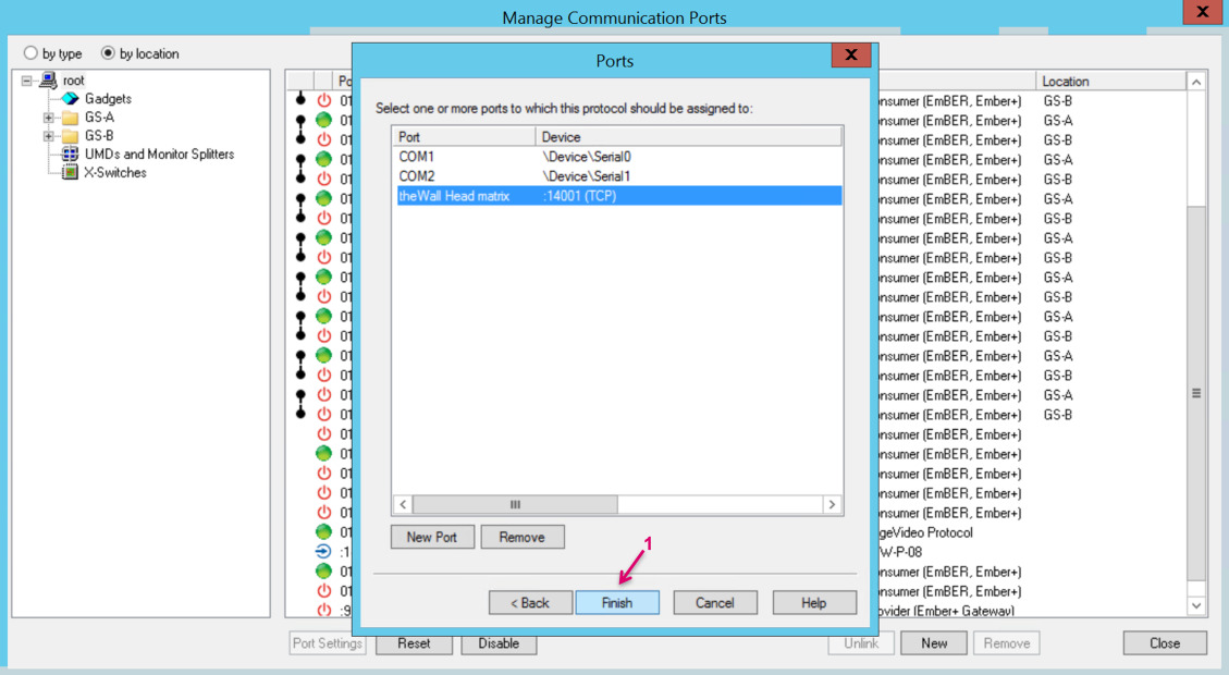
Proceed the setup by clicking Finish (1).
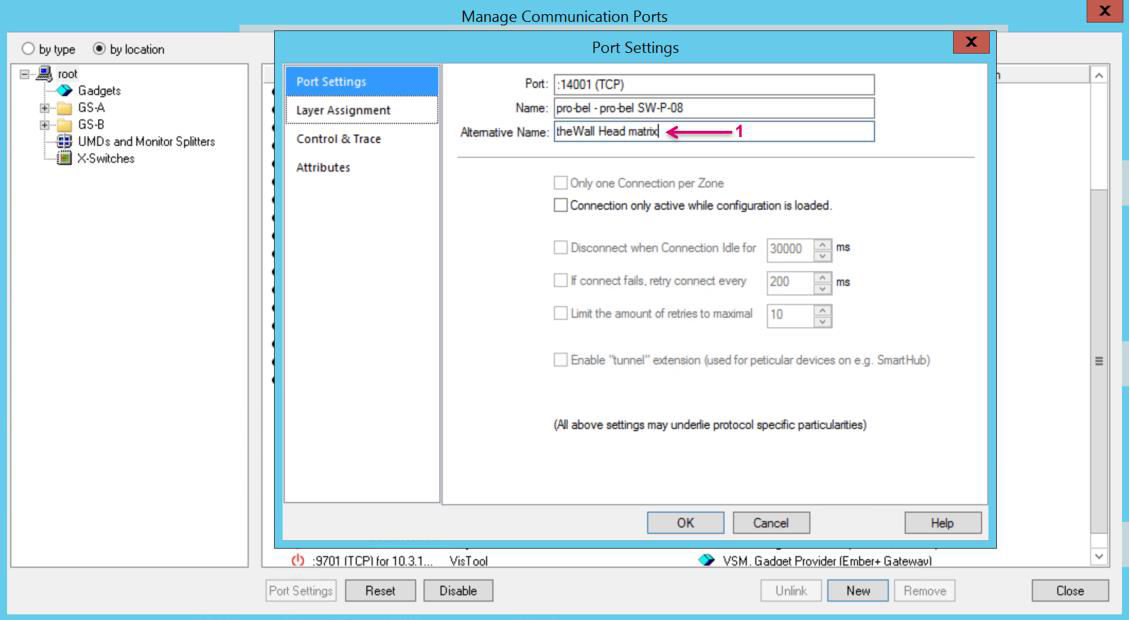
In the Port Settings window add an Alternative Name (1) for a clearer display in the Manage Communication Ports view. This may be just the same as used for Description Name before.
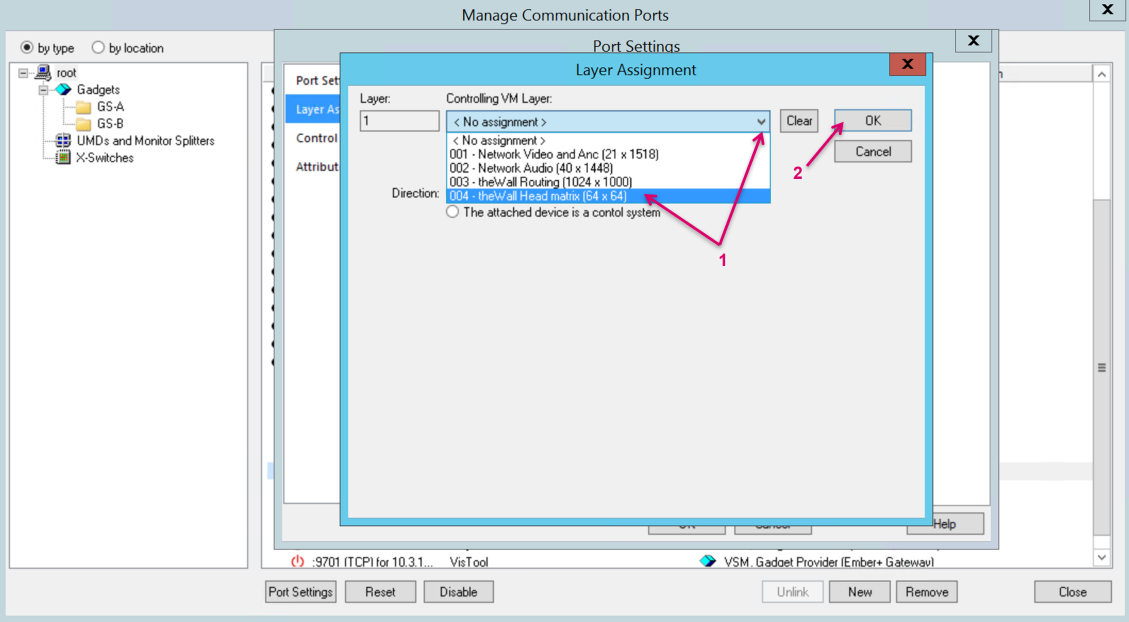
Select Layer Assignment (1) from the menu bar. Double-click on Layer 01.00 (2).

To map the vLayer to the communication port, select the respecting VM Layer from the drop-down menu (1). Confirm with OK (2).
Set the port Direction to The attached device is a control system (1). Confirm with OK (2).
The port setup is now complete, and the port is listed in the Manage Communication Ports view (1). Unless you need to set up another control port you can Close the window (2).
An Inbound connection shows no active communication status. Also, in case you need to reset an Inbound port on vsmStudio side, use the Disable/ Enable control (3) instead of Reset.