.edge - Advanced -> System controls
The System controls provide diagnostic tools and global options.
Operation (using HOME)
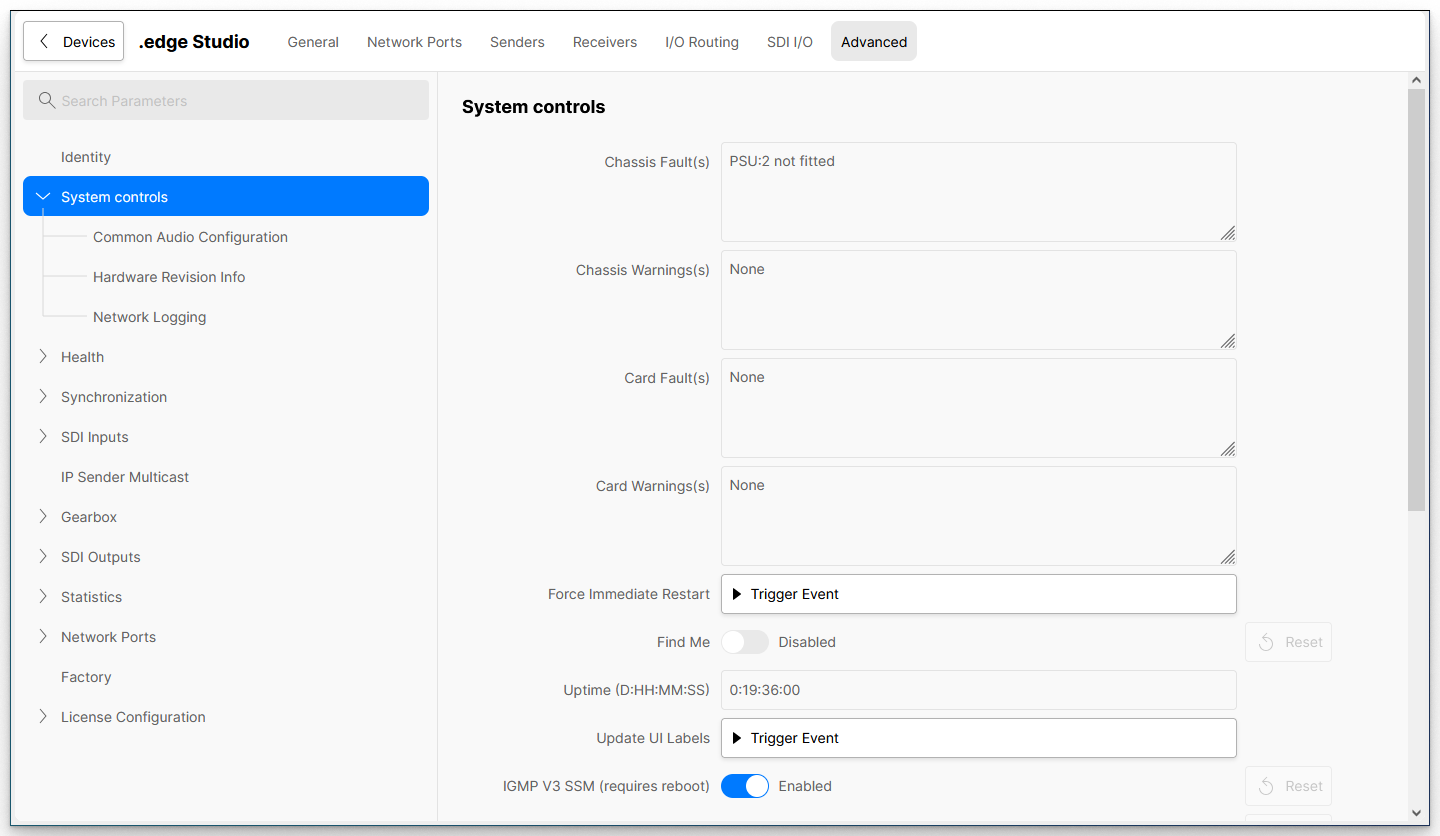
From the main page you can check the chassis and card faults/warnings, force a restart of the processing blade or adjust the blade's global options.
There are also three sub-pages as follows:
- Common Audio Configuration - can be used to set the number of audio channels (for IP senders/receivers) or adjust the audio test tone levels.
- Hardware Revision Info - displays information about the hardware fitted to the processing blade.
- Network Logging - can be used to forward log data to an external centralised logging solution.
System controls
| System Controls | |||
|---|---|---|---|
| Parameter | Possible Values | Description | |
| Chassis Fault(s) | Read-only | The first four fields show information about any chassis and card faults/warnings These feed into the Card Status LED on the front of the blade. | |
| Chassis Warning(s) | Read-only | ||
| Card Fault(s) | Read-only | ||
| Card Warning(s) | Read-only | ||
| Force Immediate Restart | Trigger Event | Use Trigger Event to force a restart. This is the same as using the Reboot option (from the "Devices" list) or the recessed Reset button (on the front of the blade). | |
| Find Me | Enabled/Disabled | Turns on the "Identify Hardware" function. | |
| Uptime | Read-only | Displays the running time of the processing blade since the last restart/reboot. D = number of days; HH:MM:SS = time (in hours, minutes and seconds). | |
| Update UI Labels | Trigger Event | Use Trigger Event to push any label updates (e.g. for SDI ports) to the user interface. | |
| IGMP V3 SSM | Enabled/Disabled | Enables or disables IGMP V3. Requires a reboot of the blade to take effect. | |
| UDP Dest Port Filter | Enabled/Disabled | Enables or disables the UDP Destination Port filter. Requires a reboot of the blade to take effect. | |
| Rest API Enable | Enabled/Disabled | Enables or disables external control via Rest API. | |
| Rest API Port | Numerical entry | Defines the port number used for Rest API. | |
| ST2110 Single SRD Mode | Enabled/Disabled | Can be used to enable single SRD mode for all ST2110 IP senders. This option is described in more detail below. | |
| NATS Server IP/Hostname | Text entry | Works with the Set NATS IP/Hostname field. It can be used to tell the blade where the system's NATS server is running, usually on the HOME server (nats.home). | |
| Set NATS IP/Hostname | Trigger Event | Use Trigger Event to apply a change to the NATS Server IP/Hostname field. | |
| Warning: If you are controlling the blade via HOME, then changing the NATS Server IP/Hostname to an incorrect setting will render the blade unreachable (by HOME). | ||
Single SRD Mode
SRD = Sample Row Data
SRDs are small chunks of data within packets of ST2110-20 streams which represent part of the active picture.
To provide the most efficient packing of data in the stream, if there is available space in a packet at the end of a video line, .edge fills the space with data from the next video line. This means that, by default, some packets contain data from two different video lines (and contain two SRDs).
As some third-party devices are unable to process data packed in this fashion, the Single SRD Mode is provided. When enabled, .edge packs the data so that no single packet contains data from more than one video line.
When developing this feature it was essential that all data packets were exactly the same size. So, the single SRD mode chooses the number of pixels its puts in each packet to ensure that all packets are the same size.
Please note:
- The ST2110 Single SRD Mode is a global option (for the blade) that applies to all IP senders.
- When ST2110 Single SRD Mode is enabled, the data packing is less efficient and will lead to a slight increase in network bandwidth usage (RTP packets could be smaller, but more of them).
Common Audio Configuration
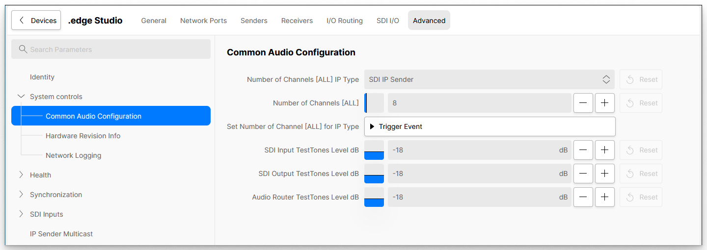
The Common Audio Configuration sub-page can be used for two functions:
- to set the number of audio channels for all IP senders or receivers of a particular type.
- to adjust the audio level of the test tone generators.
Audio Channels for IP Senders/Receivers
The first three fields provide a quick way to set the number of audio channels for all IP senders or receivers of a particular type: SDI senders, SDI receivers, Audio Matrix senders or Audio Matrix receivers.
In each case, you will need to prepare the new value and then apply the change (using Trigger Event). You can repeat the process to set a different number of audio channels for each IP Type.
Advanced page (tree path): System controls → Common Audio Configuration.
| System controls → Common Audio Configuration | ||||
|---|---|---|---|---|
| Parameter | Possible Values | Description | ||
Number of Channels [ALL] IP Type | - SDI IP Sender | Use this field to choose the audio sender or receiver type (e.g. SDI IP Sender). | ||
| Number of Channels [ALL] | Numerical entry | Use this field to set the required number of audio channels (e.g. 8). | ||
Set Number of Channels [ALL] for IP Type | Trigger Event | Use Trigger Event to apply the change. For example, to set the number of audio channels for all SDI IP senders to 8. | ||
Audio Test Tone Generator Levels
The next three fields set the audio levels of the test tone generators. In each case, you can either type in a valid number or click on the +/- buttons (to increment/decrement the value). Any change is applied immediately.
| System controls → Common Audio Configuration | |||||
| Parameter | Possible Values | Range (dB) | Description | ||
|---|---|---|---|---|---|
| SDI Input TestTones Level dB | Numerical entry | -30 to 0 | Sets the audio level of the test tone generator for all SDI Inputs. | ||
| SDI Output TestTones Level dB | Numerical entry | -30 to 0 | Sets the audio level of the test tone generator for all SDI Outputs. | ||
| Audio Router TestTones Level dB | Numerical entry | -30 to 0 | Sets the audio level of the test tone generator for the Audio Router. | ||
Hardware Revision Info
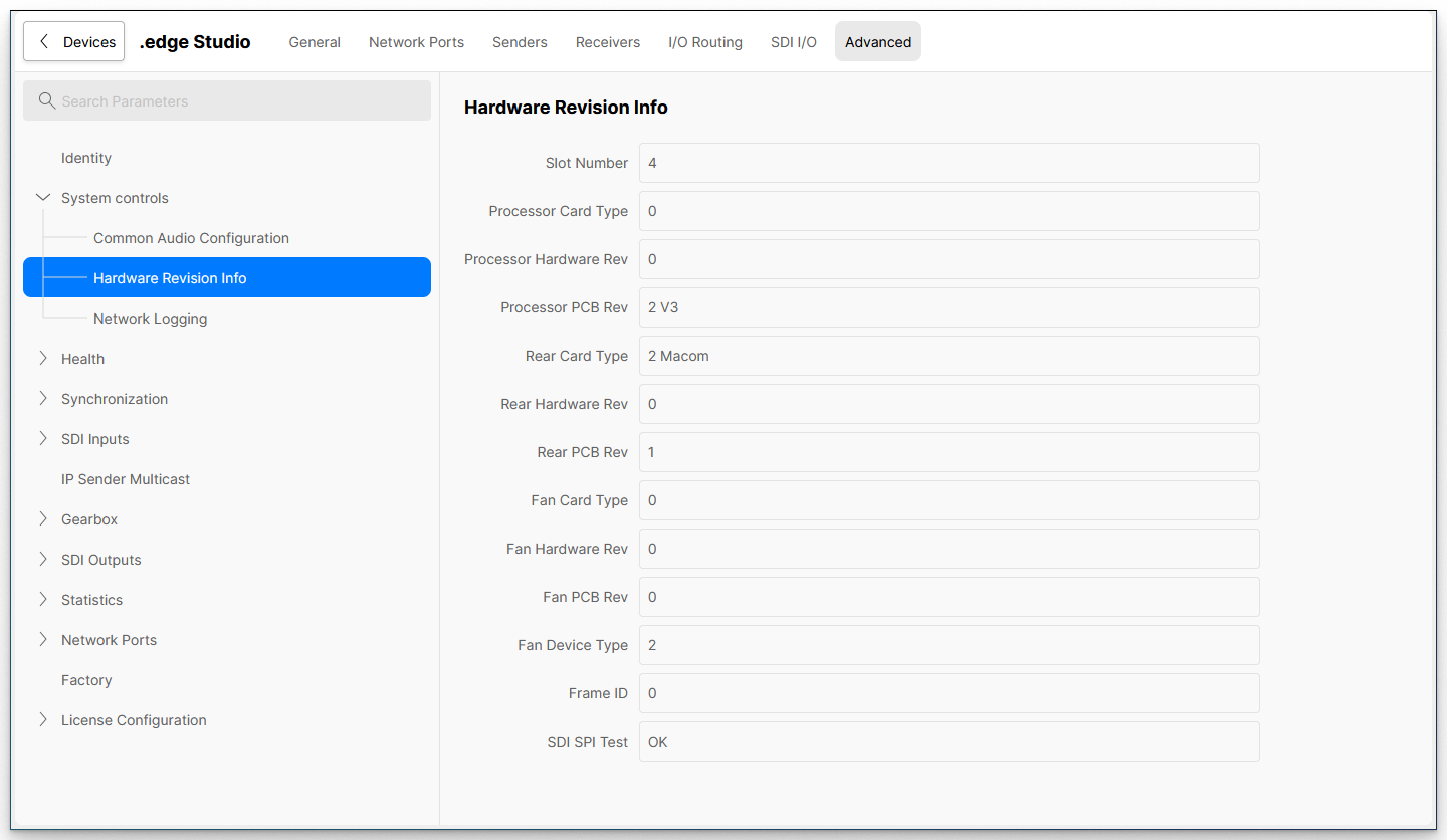
The Hardware Revision Info sub-page displays information about the hardware fitted to the processing blade. All fields are for information only.
Network Logging
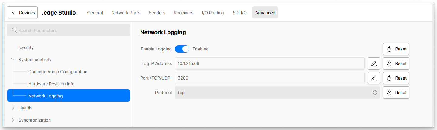
The Network Logging sub-page can be used to forward log data to an external centralised logging solution, such as the Loki service (running on HOME).
Loki is a centralised log message handling service (that runs on HOME). Lots of devices can send logs to Loki. Users then have a single place to find them.
| System controls → Network Logging | ||||
| Parameter | Possible Values | Description | ||
|---|---|---|---|---|
| Enable Logging | Enabled/Disabled | When enabled, log data is forwarded to the IP address / Port number (defined below). | ||
| Log IP Address | Text entry, valid IP | Sets the IP address used for forwarding. e.g. enter the IP address of HOME which is running Loki. | ||
| Port | Text entry, valid port | Sets the Port number used for forwarding. This should be set to 3200 (for Loki). | ||
| Protocol | - TCP | Sets the protocol used. | ||