vsmLTC
DISCONTINUED PRODUCT
![]() (E) Warning / (F) Avertissement
(E) Warning / (F) Avertissement
Please click on the link below to open the booklet as a pdf:
![]() (E) ATTENTION
(E) ATTENTION
DO NOT spill liquids into any system components!
DO NOT clean the front panels or operational surfaces with sharp instruments.
![]() (F) ATTENTION
(F) ATTENTION
NE PAS renverser de liquides dans les composants du système!
NE PAS nettoyer les panneaux avant ou les surfaces opérationnelles avec des instruments pointus.
![]() (E) IMPORTANT NOTE
(E) IMPORTANT NOTE
General Cleaning / Disinfecting Requirements
Lawo hardware products are made from a variety of different materials, and each material might have specific cleaning requirements. Therefore, a general allowance for the disinfection of product surfaces with disinfectants containing alcohol cannot be given.
Our front panels and operational surfaces are not entirely approved for treatment with chemical cleaning agents and disinfectants. Component surfaces, buttons and electronics can be permanently damaged by treatment with such agents and the lifespan can be dramatically shortened. Please note that some substances can lead to discoloration of surfaces.
Lawo is not responsible for damage caused by the unauthorized use of disinfectants on our products and surfaces. Damages caused by unspecified treatment of modules and components are not covered by regular or extended warranties or SLA regulations.
This is a general instruction and recommendation for cleaning that applies to all Lawo products:
- Before cleaning the device, unplug all external power sources.
- Clean the device with a soft cloth, dipped lightly in warm to hot soapy water.
- Do not use any liquid cleaning agents or spray cleaners that may contain flammable materials.
- Do not get moisture into any openings.
- Do not use aerosol sprays, bleaches, or abrasives.
- Do not spray cleaners directly onto the item.
The above information and our technical application advice are given to the best of our knowledge.
Introduction
The vsm LTC Time Sync is an interface between a longitudinal time code signal and a USB port. The LTC signal can be used to provide a PC or server with timecode synchronisation through the LTC. The LTC Time Sync unit comes with an additional video-sync input, which is currently not used to synchronize vsmStudio server with vTimeSync. The device accepts all LTC signals according SMPTE 12M (-1/-2)/EBU timecode standard. The interface supports PAL/NTSC-Standard, but no NTSC-Drop-Frame-Mode.
Features:
- 2 LTC time code input via SUB-D15 female for PAL/NTSC-Standard.
- 2 Serial RS232 port "output" via SUB-D9 female for redundancy application only.
- 2 USB ports via USB device connector for Interface with vTimeSync on vsm server.
- 2 video sync input (black burst) 75 Ohm via BNC.
Product Overview
vsmLTC Time Sync Unit Dual
| Number of ports | 2 x LTC longitudinal timecode audio signal |
Communication port | 2 x USB | |
Dimension | 483mm x 43,7mm x 125,4mm (WxHxD):1RU | |
Weight | approx. 1,4KG | |
Power-Consumption | <10W | |
Working-Environment | 0°C-60°C non-condensing humidity |

Operating Conditions
This device is built to be used in a non-condensing environment within a temperature range of 0-50°C. Under or overshooting this working temperature range may cause fast aging of components or even malfunction of the whole device.
Spillage of any liquids e.g. coffee, coke, water... onto/into the device may cause damage.
The storage temperature of the device must be within -20°C to 60°C with a maximum of 75% non-condensing relative humidity at 60°C @ 0VDC supply-voltage.
DO NOT throw, drop or bend the unit and make sure that there is no strong permanent mechanical pressure on any side of the housing at any time.
Before installing or using this device, always read and observe the Important Safety Instructions.
Preparing for Operation
All servers running vTimeSync (the synchronisation application for VSM Studio) will be shipped with pre-installed and pre-configured USB driver. If you need to install the USB driver please download the latest version here or contact our support team.
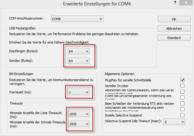
First properly install the USB driver and connect the LTC Time Sync unit to the server. If Windows has detected the LTC Time Sync unit go to "Device Manager/Ports (COM & LTP)/COM port number (LTC IF)". Find the Tab "Port Settings" and go to Advanced Settings. Now configure the LTC Time Sync unit USB port as the following, press "OK" and restart Windows if needed.
Now connect the LTC signal to the device. After ca. 30 seconds the device will show at the front status LEDs the LTC online state.
Open the "Gui.html" file in the vTimeSync installation folder or use this link to setup the COM Port for vTimeSync as following:
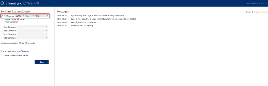
If the "Signal Source" LED turns green and the "Proxy Version" shows a valid Firmware Version, vTimeSync has established a valid connection to the LTC Time Sync unit. For further information about vTimeSync read the corresponding manual.
Technical Specifications
Status LEDs
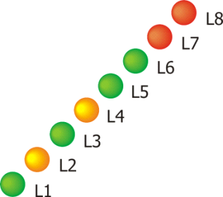
Legend for the front status LED
| Scheme | Nr | Color | Meaning |
|---|---|---|---|
| L1 | Green | Power/Ready |
| L2 | Yellow | Physical connection to PC established | |
| L3 | Green | RTC available | |
| L4 | Yellow | Backup source operation | |
| L5 | Green | V-Sync Online | |
| L6 | Green | LTC Online | |
| L7 | Red | V-Sync Error | |
| L8 | Red | LTC Error |
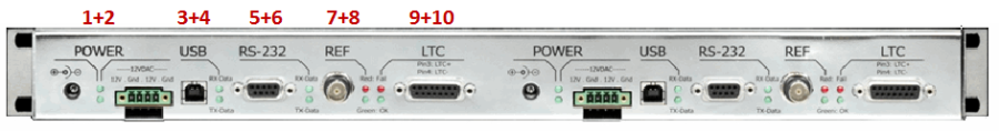
Legend for the rear status LED's
| ||
| 1+2 | Green + Green | Power good (internal regulator) |
| 3+4 | Green + Green | RX/TX indicator for USB port |
| 5+6 | Green + Green | RX/TX indicator for RS232 port |
| 7+8 | Red + Green | Video sync reference status, red: fail green: ok |
| 9+10 | Red + Green | LTC status information red: fail green: ok |
Connectors
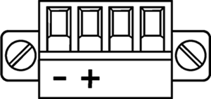
Power Connector
Connector for DC-supply: 4-Pin connector (MC 1,5/ 4-STF-3,81) locked with two screws. The connector is already mounted on the power-supply delivered with each vsmLTC interface.
Power Supply
| Product | Description | Item Number |
|---|---|---|
| LBP-PSU (Phoenix-Plug) | 12V DC power supply, 4-Pin-Phoenix-Type | 799-0089-000 |
(EN) Warning
Important: It is understood that only the external Power-Supply-Unit (PSU) provided by Lawo, and shipped with the specific vsm device, is used for operating the product.
To feed the device via the DC input it is mandatory to use a 12V power source that is certified as “SELV/LPS” (if certified according to 60950) or as “ES1/PS2(LPS)” (if certified according to 62368) “NEC Class 2” 12V power source. The UL mark is valid only with use of UL certified PSUs of categories QQGQ (UL 60950) or QQJQ (UL 62368). The supplied Lawo 12V PSU is compliant to these requirements.
(F) Avertissement
Important: Il est entendu que seul le bloc d'alimentation externe fourni par Lawo, et livré avec le dispositif vsm spécifique, est utilisé pour faire fonctionner le produit.
Pour alimenter l'appareil via l'entrée DC, il est obligatoire d'utiliser une source d'alimentation 12V conforme aux exigences «SELV / LPS» (si certifiée selon la norme IEC 60950) ou «ES1 / PS2 (LPS)» (si certifiée selon la norme IEC 62368) Source d'alimentation 12V “NEC Classe 2”. La marque UL est seulement valable quand l'alimentation elle-même est certifiée par UL dans les catégories QQGQ (norme UL 60950) ou QQJQ (norme UL 62368). Le bloc d’alimentation Lawo 12V fourni avec l’équipement est conforme à ces exigences.
LTC
Sub-D15 female |

The output-impedance of the LTC-generator should be as small as possible; the level is preferred to be adjustable. The LTC-interface input-level must be within SMPTE-restriction 12M:
SMPTE 12M-1995 < 50 W/1 - 2 Vpp (max. 0.5 - 4.5 Vpp), following EBU Tech. 3097-E < 30 W/0.5 - 4.5 Vpp
Pin | Signal | Comments |
|---|---|---|
1 | NC | - |
2 | NC | - |
3 | LTC-A | LTC data + (HOT) |
4 | LTC-B | LTC data - (COLD) |
5 | GND* | AC-coupled ground (GND) |
6 | NC | - |
7 | NC | - |
8 | NC | - |
9 | NC | - |
10 | NC | - |
11 | NC | - |
12 | NC | - |
13 | NC | - |
14 | NC | - |
15 | NC | - |
USB
USB device |
|

Pin | Signal | Comments |
|---|---|---|
1 | VCC | + 5V |
2 | D- | Data - |
3 | D+ | Data + |
4 | GND | GND |
Serial Redundancy Interface
Sub-D9 male RS232 (EIA RS232D 2.1.7) |
|

Pin | Signal | Comments |
|---|---|---|
1 | NC | - |
2 | RxD | Receive Data input |
3 | TxD | Transmit Data output |
4 | NC | - |
5 | GND | Ground (shield) |
6 | NC | - |
7 | NC | - |
8 | NC | - |
9 | NC | - |
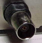
REF Input/Blackburst
BNC 75 Ohm (PAL/NTSC/SECAM) |
|
Pin | Signal | Comments |
|---|---|---|
1 | Composite | Positive video signal |
2 | Drain | Shield (GND) |