vsmCrosspointInterface
DISCONTINUED PRODUCT
![]() (E) Warning / (F) Avertissement
(E) Warning / (F) Avertissement
Please click on the link below to read or download the booklet as a pdf.
![]() (E) ATTENTION
(E) ATTENTION
DO NOT spill liquids into any system components!
DO NOT clean the front panels or operational surfaces with sharp instruments.
![]() (F) ATTENTION
(F) ATTENTION
NE PAS renverser de liquides dans les composants du système!
NE PAS nettoyer les panneaux avant ou les surfaces opérationnelles avec des instruments pointus.
![]() (E) IMPORTANT NOTE
(E) IMPORTANT NOTE
General Cleaning / Disinfecting Requirements
Lawo hardware products are made from a variety of different materials, and each material might have specific cleaning requirements. Therefore, a general allowance for the disinfection of product surfaces with disinfectants containing alcohol cannot be given.
Our front panels and operational surfaces are not entirely approved for treatment with chemical cleaning agents and disinfectants. Component surfaces, buttons and electronics can be permanently damaged by treatment with such agents and the lifespan can be dramatically shortened. Please note that some substances can lead to discoloration of surfaces.
Lawo is not responsible for damage caused by the unauthorized use of disinfectants on our products and surfaces. Damages caused by unspecified treatment of modules and components are not covered by regular or extended warranties or SLA regulations.
This is a general instruction and recommendation for cleaning that applies to all Lawo products:
- Before cleaning the device, unplug all external power sources.
- Clean the device with a soft cloth, dipped lightly in warm to hot soapy water.
- Do not use any liquid cleaning agents or spray cleaners that may contain flammable materials.
- Do not get moisture into any openings.
- Do not use aerosol sprays, bleaches, or abrasives.
- Do not spray cleaners directly onto the item.
The above information and our technical application advice are given to the best of our knowledge.
Introduction
The vsm Crosspoint Interface is specifically designed to connect to Grass Valley routers via the Cross Point-Bus to vsmStudio. In case of power-loss, the Crosspoint Interface stores the latest crosspoints to non-volatile memory, so there is no loss of crosspoints during a power cycle.
The connection between the Crosspoint Interface and vsmStudio is established through Ethernet. For redundancy, two Crosspoint Interfaces can be connected together to one Grass Valley unit. An internal handler will calculate which interface is the master and which is the slave, so if one interface fails, the other one will take over communication.
An optional REF-signal input for black-burst reference and an LTC-input on the rear of the Crosspoint Interface unit is implemented for future use.
Product Overview
vsmCrosspoint Interface
| Number of Ports | 1 x XPT-Bus for GrassValley routers |
Options | Redundant System | |
| Communication Port | 1 x Ethernet | |
Dimensions | 483mm x 43,7mm x 225mm (WxHxD):1RU | |
Weight | approx. 2,1KG | |
Power-Consumption | <10W | |
Working-Environment | 0°C-60°C non-condensing humidity |
Operating Conditions
This device is built to be used in a non-condensing environment within a temperature range of 0-50°C. Under or overshooting this working temperature range may cause fast aging of components or even malfunction of the whole device.
Spillage of any liquids e.g. coffee, coke, water... onto/into the device may cause damage.
The storage temperature of the device must be within -20°C to 60°C with a maximum of 75% non-condensing relative humidity at 60°C @ 0VDC supply-voltage.
DO NOT throw, drop or bend the unit and make sure that there is no strong permanent mechanical pressure on any side of the housing at any time.
Before installing or using this device, always read and observe the Important Safety Instructions.
Preparing for Operation
All Lawo devices will be shipped with DHCP enabled network configuration. If you don't have a DHCP network ask your administrator for static network settings and edit the "Network" section if required.
Do the following settings in VSM Discover: ![]()

Press the "Apply" button if you are sure you have entered the settings correctly. The device will automatically perform a reboot to apply the network configuration.
To connect a device to vsmStudio enter the IP Address of Server 1 – 4 (depending on how many vsmStudio servers are configured) in the "Application" section. This connection will also be used for any future firmware updates. If the system is working in redundant mode, connect both devices to Server 1 – 4 as the crosspoint synchronisation needs a valid time reference from vsmStudio to both units.

Now the device can be configured with vsmStudio:
- Go to "Communication Ports" and make a new connection.

- Navigate to pro-bel SW-P-08 protocol.

- On Next Page select "New Port".
- Use the device IP Address and TCP-Port 8001 to create an outbound vsmStudio connection to the Crosspoint Interface and press "OK".
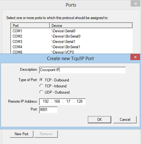
- Select the created port and press "Finish".
- Assign the router ID to a corresponding vsmStudio layer (up to 16 layer) and acknowledge all windows.
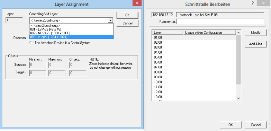
- The created port should now appear in the "Communication Ports" list with a green LED.
Technical Specifications
Status LEDs
Rear Status LEDs CPU
| |||
| LED | Color | Status | Meaning |
|---|---|---|---|
| 1 | Blue | Blink | Data transfer to vsmStudio |
| 2 | Red | Blink | no connection to vsmStudio |
| 3 | Green | Steady on | 5V internal coltage OK |
| 4 | Green | Steady on | 3,3V internal voltage OK |
| 5 | Orange | Steady on | physical LAN connection |
| 6 | Green | Blink | Data transfer via LAN |
Rear Status LED XTP-Bus
| Color | Status | Meaning |
|---|---|---|
| Red | Fast Blink | loading stored crosspoints from EEPROM, initializing |
| Blue | Blink | XPT-Bus ready, no valid connection to GV-Router detected. |
| Blue / Green | Alternate Blinking | valid communication to GV-Router. |
| Orange | Steady on | physical LAN connection |
| Green | Blink | Data transfer via LAN |
Connectors
Phoenix MC 1,5/ 4-STF-3,81
Connector for DC-supply: 4-Pin connector (MC 1,5/ 4-STF-3,81) locked with two screws.
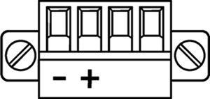
Power Supply
| Product | Description | Item Number |
|---|---|---|
| LBP-PSU (Phoenix-Plug) | 12V DC power supply, 4-Pin-Phoenix-Type | 799-0089-000 |
(EN) Warning
Important: It is understood that only the external Power-Supply-Unit (PSU) provided by Lawo, and shipped with the specific vsm device, is used for operating the product.
To feed the device via the DC input it is mandatory to use a 12V power source that is certified as “SELV/LPS” (if certified according to 60950) or as “ES1/PS2(LPS)” (if certified according to 62368) “NEC Class 2” 12V power source. The UL mark is valid only with use of UL certified PSUs of categories QQGQ (UL 60950) or QQJQ (UL 62368). The supplied Lawo 12V PSU is compliant to these requirements.
(F) Avertissement
Important: Il est entendu que seul le bloc d'alimentation externe fourni par Lawo, et livré avec le dispositif vsm spécifique, est utilisé pour faire fonctionner le produit.
Pour alimenter l'appareil via l'entrée DC, il est obligatoire d'utiliser une source d'alimentation 12V conforme aux exigences «SELV / LPS» (si certifiée selon la norme IEC 60950) ou «ES1 / PS2 (LPS)» (si certifiée selon la norme IEC 62368) Source d'alimentation 12V “NEC Classe 2”. La marque UL est seulement valable quand l'alimentation elle-même est certifiée par UL dans les catégories QQGQ (norme UL 60950) ou QQJQ (norme UL 62368). Le bloc d’alimentation Lawo 12V fourni avec l’équipement est conforme à ces exigences.
XPT-Bus
XPT-Bus Termination
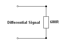
In the middle of the two 15-pin SUB-D connectors for the XPT-Bus on the rear side of the Crosspoint Inferface there are 2 dip-switches for enabling termination on SUB-D-connector.
The termination of the connector can be enabled separately for the two XPT-connectors. The termination should only be used for optional termination-purposes for very long cable-traces in very noisy environment. This termination-option is not needed in most cases; therefore the DIP-switches should remain "off" as a default setting.
Circuit diagram for optional termination of XPT-Bus:
Redundancy on Crosspoint IF
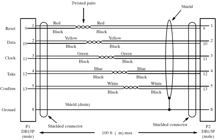
To build a redundant interface you need to connect two Crosspoint Interfaces by the enclosed 15-pin SUB-D Crosspoint-redundancy cable. You also need the 25-pin SUB-D TMIO-cable and the RJ-45 redundancy cable.
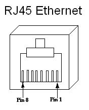
1 x RS422 via RJ45 connector for redundant option only. Use enclosed RJ-45-redundancy cable only.
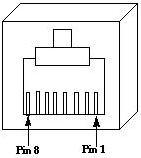
Pin | Comments | |
|---|---|---|
1 | NC | - |
2 | NC | - |
3 | Rx+ | Receive Data input |
4 | Tx+ | Transmit Data output |
5 | Tx- | Transmit Data output |
6 | Rx- | Receive Data input |
7 | NC | - |
8 | NC | - |
Serial Baud Rate will be configured automatically by the device to 115200 Baud.
1 x TMIO via SUB-D25 connector for redundant option only. Use enclosed SUB-D25 male/male cable only.
Ethernet
For standard operation each device is connected to an Ethernet-switch where the individual port of the switch should be set to "Auto-Negotiation". If you have communication-problems with "Auto-Negotiation" mode, set this individual port of the Ethernet-Switch to "100Mbit Full Duplex-Mode" also setting the Crosspoint Interface device in vsmDiscover to "Fixed 100MBit-Full Duplex: True"
Pin | Signal | Color of a standard TIA-568A-shielded twisted pair patch cable (CAT5 or higher) | Scheme |
|---|---|---|---|
1 | TX+ | white/green |
|
2 | TX- | green | |
3 | RX+ | white/orange | |
4 | NC | blue | |
5 | NC | white/blue | |
6 | RX- | orange | |
7 | NC | white/brown | |
8 | NC | brown |
Notice for wiring:
- NC: No connection; do not connect to any signal or supply.
- Only use shielded CAT5 (or higher standard) -specified networkable. Refer to TIA-568A or TIA-568B for wiring.
- Do not use cable-traces longer than 100m (328ft) between the device and the network-switch for 100BASE-T communication.
- Make sure to comply to wiring standards and use shielded RJ45-plugs for shielded cable on both ends of the line.


