vsmGPIOBox - GPIO Interface
Introduction
A vsmGPIOBox is the hardware interface between Ethernet and a specific number of digital general purpose ports. The number of inputs and/or outputs and their type depends on the box in use. This guide provides you with all the information that is required in order to integrate a GPIO Box into a vsmStudio.
Technical Specifications
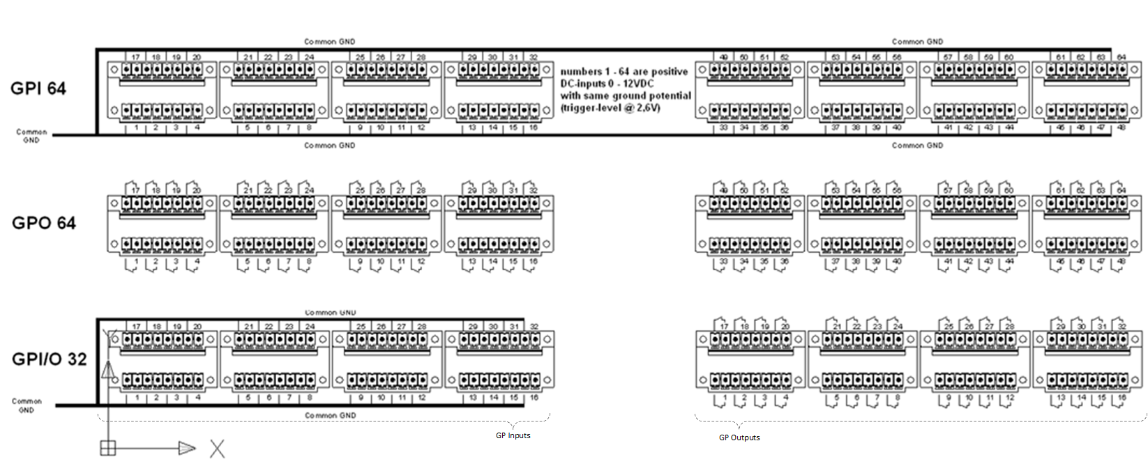
vsmGPI 64
| Number of ports | 64 galvanically isolated TTL-compatible inputs |
| Frontside port types | Input Only | |
Communication port | 1 x Ethernet | |
Dimension | 483mm x 43,7mm x 127,3mm (WxHxD): 1 RU | |
Weight | pprox. 1,9KG | |
Power-Consumption | < 30W | |
Working-Environment | 0°C-60°C non condensing humidity |

vsmGPO 64
| Number of ports | 64 dry relay-outputs |
| Frontside port types | Output Only | |
Communication port | 1 x Ethernet | |
Dimension | 483mm x 43,7mm x 127,3mm (WxHxD): 1 RU | |
Weight | pprox. 2,3KG | |
Power-Consumption | < 30W | |
Working-Environment | 0°C-60°C non condensing humidity |
vsmGPIO 32
| Number of ports | 32 galvanically isolated TTL-compatible inputs |
| Frontside port types | Left: Input , Right: Output | |
Communication port | 1 x Ethernet | |
Dimension | 483mm x 43,7mm x 127,3mm (WxHxD): 1 RU | |
Weight | approx. 2,1KG | |
Power-Consumption | < 30W | |
Working-Environment | 0°C-60°C non condensing humidity |
Operating Conditions
This device is built to be used in a non-condensing environment within a temperature range of 0-60°C. Under or overshooting this working temperature range may cause fast aging of components or even malfunction of the whole device.
Spillage of any liquids e.g. coffee, coke, water... onto/into the device may cause damage.
The storage temperature of the device must be within -20°C to 60°C with a maximum of 75% non-condensing relative humidity at 60°C @ 0VDC supply-voltage.
DO NOT throw, drop or bend the unit and make sure that there is no strong permanent mechanical pressure on any side of the housing at any time.
![]() (E) Warning / (F) Avertissement
(E) Warning / (F) Avertissement
Please click on the link below to open the booklet as a pdf:
![]() (E) ATTENTION
(E) ATTENTION
DO NOT spill liquids into any system components!
DO NOT clean the front panels or operational surfaces with sharp instruments.
![]() (F) ATTENTION
(F) ATTENTION
NE PAS renverser de liquides dans les composants du système!
NE PAS nettoyer les panneaux avant ou les surfaces opérationnelles avec des instruments pointus.
![]() (E) IMPORTANT NOTE
(E) IMPORTANT NOTE
General Cleaning / Disinfecting Requirements
Lawo hardware products are made from a variety of different materials, and each material might have specific cleaning requirements. Therefore, a general allowance for the disinfection of product surfaces with disinfectants containing alcohol cannot be given.
Our front panels and operational surfaces are not entirely approved for treatment with chemical cleaning agents and disinfectants. Component surfaces, buttons and electronics can be permanently damaged by treatment with such agents and the lifespan can be dramatically shortened. Please note that some substances can lead to discoloration of surfaces.
Lawo is not responsible for damage caused by the unauthorized use of disinfectants on our products and surfaces. Damages caused by unspecified treatment of modules and components are not covered by regular or extended warranties or SLA regulations.
This is a general instruction and recommendation for cleaning that applies to all Lawo products:
- Before cleaning the device, unplug all external power sources.
- Clean the device with a soft cloth, dipped lightly in warm to hot soapy water.
- Do not use any liquid cleaning agents or spray cleaners that may contain flammable materials.
- Do not get moisture into any openings.
- Do not use aerosol sprays, bleaches, or abrasives.
- Do not spray cleaners directly onto the item.
The above information and our technical application advice are given to the best of our knowledge.
Status LEDs
| |||
| LED | Color | Status | Meaning |
|---|---|---|---|
| 1 | RGB | Blue, Steady on | internal serial I/O controller OK, green: serial TX, red: serial RX. |
| 2 | RGB | Red Pulse | no connection to the network |
| Red Fast Blink | device in bootloader-mode | ||
| Yellow Pulse | network connection established | ||
| Blue Pulse | connected to vsmStudio | ||
| 3 | Green | Steady on | processor core-voltage OK |
| 4 | Green | Steady on | internal I/O-voltage OK |
| 5 | Orange | Blink | physical LAN connection / TCP/IP-data-transfer |
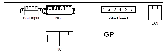
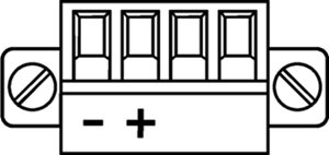
Power Connector
Phoenix MC 1,5/ 4-STF-3,81
Connector for DC-supply: 4-Pin connector (MC 1,5/ 4-STF-3,81) locked with two screws. The connector is already mounted on the power-supply delivered with each GPIO-Box.
Power Supply
Product | Description | Item Number |
|---|---|---|
LBP-PSU (Phoenix-Plug) | 12V DC power supply, 4-Pin-Phoenix-Type | 799-0089-000 |
![]() (EN) Warning
(EN) Warning
It is understood that only the external Power-Supply-Unit (PSU) provided by Lawo, and shipped with the specific vsm device, is used for operating the product.
To feed the device via the DC input (exempt power core) it is mandatory to use a 12V power source that is certified as “SELV/LPS” (if certified according to 60950) or as “ES1/PS2(LPS)” (if certified according to 62368) “NEC Class 2” 12V power source. The UL mark is valid only with use of UL certified PSUs of categories QQGQ (UL 60950) or QQJQ (UL 62368). The supplied Lawo 12V PSU is compliant to these requirements.
![]() (F) Avertissement
(F) Avertissement
Il est entendu que seul le bloc d'alimentation externe fourni par Lawo, et livré avec le dispositif vsm spécifique, est utilisé pour faire fonctionner le produit.
Pour alimenter l'appareil via l'entrée DC, il est obligatoire d'utiliser une source d'alimentation 12V conforme aux exigences «SELV / LPS» (si certifiée selon la norme IEC 60950) ou «ES1 / PS2 (LPS)» (si certifiée selon la norme IEC 62368) Source d'alimentation 12V “NEC Classe 2”. La marque UL est seulement valable quand l'alimentation elle-même est certifiée par UL dans les catégories QQGQ (norme UL 60950) ou QQJQ (norme UL 62368). Le bloc d’alimentation Lawo 12V fourni avec l’équipement est conforme à ces exigences.
Ethernet Interface and Wiring
Ethernet Communication Port to vsmStudio
Port de communication Ethernet vers vsmStudio
Cette interface est utilisée comme port de communication Ethernet vers vsmStudio. Il est entendu que pour un fonctionnement correct, chaque LBP est connectée à un switch Ethernet dont le port individuel est réglé sur "Auto-négociation".
Pin | Signal | Color of a standard TIA-568A-shielded twisted pair patch cable (CAT5 or higher) | Scheme |
|---|---|---|---|
1 | TX+ | white/green |
|
2 | TX- | green | |
3 | RX+ | white/orange | |
4 | NC | blue | |
5 | NC | white/blue | |
6 | RX- | orange | |
7 | NC | white/brown | |
8 | NC | brown |
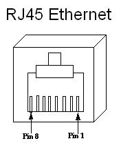
Notice for wiring:
- NC: No connection; does not connect to any signal or supply.
- Only use shielded CAT5 (or higher standard) -specified networkable. Refer to TIA-568A or TIA-568B for wiring.
- Do not use cable-traces longer than 100m (328ft) between the device and network-switch for 100BASE-T communication.
- Make sure to do standard wiring and use shielded RJ45-plugs for shielded cable on both ends of the line.
![]() (EN) Warning
(EN) Warning
It is mandatory, that copper based Ethernet connections (CAT 5, RJ45) are led inside a building to the third party-device-ethernet-switch . If the Ethernet connection needs to be led outside a building it is mandatory to use a optical fiber. Use a converter to optical fiber and connect it in a short way (inside the building) to the device.
![]() (F) Avertissement
(F) Avertissement
Il est obligatoire que les connexions Ethernet à base de cuivre (CAT 5 ou une norme supérieure, RJ45) soient installées à l'intérieur d'un bâtiment jusqu'au prochain switch Ethernet. Si la connexion Ethernet doit être dirigée à l'extérieur d'un bâtiment, utilisez un convertisseur en fibre optique et une connexion courte (à l'intérieur du bâtiment) à l'appareil.
GPIO Connector (On front side of the device)
GPI/O-Interface

Connectors for the GPI/O interface: 8-Pin connector locked with two screws (MC 1,5/ 8-STF-3,81). 16 pieces of connectors are delivered with each device. See Connector Pin-outs for wiring details.
GPI - General Purpose Input
Grounding the input pin will 'set' the device. Supplying a DC voltage, it needs to be lower than 2.6 V DC to 'set' the device. Make sure not to supply any same ground external DC-voltage exceeding 12V.
The open-circuit-voltage of the inputs is approximately 3,8V. The external current for short-circuiting the input is limited down to max 8mA.
All inputs share the same signal ground potential. Make sure not to supply any positive voltage to the ground potential.
The built-in GPI inputs follow PS1 (electrical power source class1).
The GPI input will not allow power to exceed 1W by the device itself.
Open circuit voltage GPI input: approx. 3,8V DC, max. 5V DC
Short circuit current GPI input: approx. 8mA
Loaded circuit current with externally 12V (PS1) supplied: approx. 30mA
![]() (EN) Warning
(EN) Warning
It is understood that if supplying any external voltage (DC only) to the GPI input
- it is never to exceed 12V DC rms and must also follow the PS1-rules (b-IEC 62368-1) to never source more than 15W
- check polarity if external DC-voltage is supplied
- always connect GPI input-ground to external supply-ground
- never apply any AC-voltage to the GPI inputs
![]() (F) Avertissement
(F) Avertissement
Il est entendu que si vous fournissez une tension externe (DC uniquement) à l’entrée GPI
- Il ne doit jamais dépasser 12V DC rms (valeur efficace) et doit également suivre les règles PS1 (norme b-IEC 62368-1) pour ne jamais fournir plus de 15W
- Vérifiez la polarité si une tension continue (DC) externe est fournie
- Connectez toujours la masse de l'entrée GPI à la masse de l'alimentation externe
- N’appliquez jamais de tension alternative (AC) aux entrées GPI

GPO - General Purpose Output
The GPO "outputs" are dry relay contacts. They are internally not connected to any supply or ground.
Les GPO « sorties » sont des contacts de relais secs. Ils ne sont connectés en interne à aucun approvisionnement ou terre.
![]() (EN) Warning
(EN) Warning
The relay outputs are primarily designed for low level voltage (up to 30V DC rms / 30V AC rms) that meet the following LPS requirements for the external circuit (LPS: Limited Power Source, specified in IEC 60950 and IEC 62368 safety standard):
- DC-Voltage: lower or at a maximum of 30V DC rms
- AC-Voltage: lower or at a maximum of 30V AC rms
- Maximum short circuit current of 7A
- Maximum nominal rating of 100 VA
- Maximum nominal current of 5A
- Maximal nominal power of 5A multiplied by supplied voltage needs to be < 100 VA
For safety reasons while using "higher current" make sure the current does not exceed the maximum current permitted for each relay (maximum 7 A per relay).
![]() (F) Avertissement
(F) Avertissement
Les sorties relais sont principalement conçues pour des tensions de faible niveau (jusqu'à 30V DC rms / 30V AC rms) qui répondent aux exigences LPS suivantes pour le circuit externe (LPS : Limited Power Source, spécifié dans la norme de sécurité IEC 60950 et IEC 62368) :
- Tension DC : inférieure ou égale à 30V DC rms maximum
Tension AC : inférieure ou égale à 30V AC rms maximum
- Courant de court-circuit maximal de 7A
- Puissance nominale maximale de 100 VA
- Courant nominal maximal de 5A
- La puissance nominale maximale de 5A multipliée par la tension fournie doit être < 100 VA
Pour des raisons de sécurité, lorsque vous utilisez un "courant plus élevé", assurez-vous que le courant ne dépasse pas le courant maximal autorisé pour chaque relais (maximum 7 A par relais).
High level signals and low level signals should not be run together on the same GPIO.
Les signaux de haut niveau et les signaux de bas niveau ne doivent pas être exécutés ensemble sur le même GPIO.
Professional broadcast equipment mostly uses 5 V up to 24 V DC with a maximum current of 500 mA.
Due to physical properties the usage of higher voltage and higher current causes more abrasion within the relays. This may result higher transient resistance between the switching contacts.
Once used with up to 30V and up to 7A per relay, the GPO output should not be used (in another application) with voltage below 5V and current below 100mA, to avoid the incorrect interpretation of some switching conditions.
En raison des propriétés physiques, l’utilisation d’une tension plus élevée et d’un courant plus élevé provoque plus d’abrasion dans les relais. Cela peut entraîner une résistance transitoire plus élevée entre les contacts de commutation.
Une fois utilisée avec jusqu’à 30V et jusqu’à 7A par relais, la sortie GPO ne doit pas être utilisée (dans une autre application) avec une tension inférieure à 5V et un courant inférieur à 100mA, pour éviter l’interprétation incorrecte de certaines conditions de commutation.

Connector Pin-outs
Get Ready for Operation
If all GPI-connectors are connected, the total depth of the General Purpose Interface will increase up to 140mm. Each General Purpose Interface comes enclosed with a cable-lacing bar which can be mounted to the front cover for cable management of in- and output cables. If the bracket is mounted, the complete depth of the GPI-unit will be increased by another 61mm.
All Lawo devices will be shipped with DHCP enabled network configuration. If you don't have a DHCP network ask your administrator for static network settings and edit the "Network" section if required.
Do the following settings in VSM Discover: ![]()

Press the "Apply" button if you are sure you have entered the settings correctly. The device will automatically perform a reboot to apply the network configuration.
To connect a device to vsmStudio enter the IP Address of Server 1 – 6 (depending on how many vsmStudio servers are part of the cluster) in the "Application" section. This connection will also be used for any future firmware updates.

The Location and Comment fields in the "Misc" section are to set to easily locate the device in your environment.

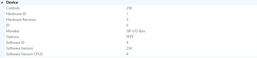
Additional read-only status and device information from vsmDiscover:

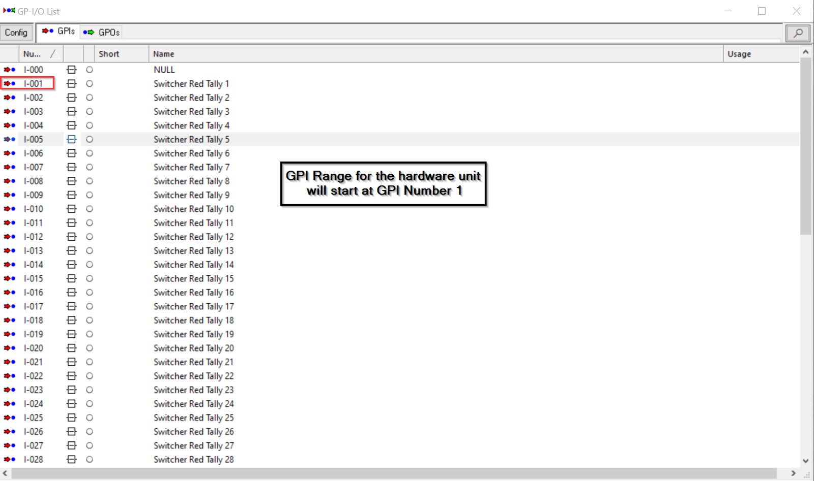
In vsmStudio, create the respective GPIs and GPOs that shall be associated with the hardware box.
Execute "regedit.exe" as Administrator on your vsmStudio server to configure the device and find the vsmStudio registry key:
HKEY_...\...\...\VirtualStudioManager\vsmStudio\Registered Devices
Allocate the MAC Address of the device in the "Registered Devices" list and use the Application Key (MAC Address with \[001\]) to enter your GPIO input and output-offsets.
To allocate the GPI and GPO ranges, select the “Base-Inputs/Base-Outputs” registry setting by double click on the respective key.

Change the “Base” setting to Decimal, then modify the “Value data” to match the desired start GPI or GPO number within your vsmStudio configuration. Once everything has been entered correctly, proceed with "OK", then reboot the device by un-/plugging the power cable. 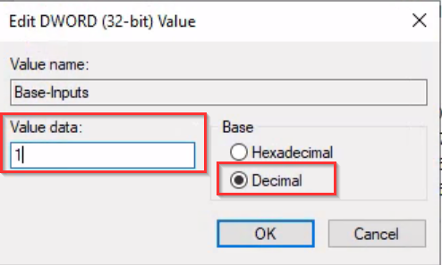
Native Ember+ Interface

Firmware version 2.35 or higher is required to use the provided native Ember+ Interface for digital GPI/O's. As long as the device has a valid connection to a vsmStudio, the Ember+ Interface is read only. The ports are represented as a One-To-N Matrix , where the matrix outputs are used as the device GPI/O ports and the matrix input is the connect/disconnect signal. Use TCP Port 9000 for the Ember+ connection.