vsmSmartHub - Serial to IP Interface
Introduction
A vsmSmartHub interfaces between Ethernet and serial RS422/RS232 ports. All devices which only have a serial interface and need to be controlled using an Ethernet network can be connected through a SmartHub. Several varieties of SmartHub can be ordered as listed below.
The SmartHub can be easily configured as serial RAW-mode or as a serial protocol converter with a variety of different protocols (please refer to section 3.3 for supported protocols).
Technical Specifications
vsmSmartHub 111
| Number of serial ports | 1xRS422 + 1xRS232 configurable via vsmDiscover |
Communication port | 1 x Ethernet | |
Dimensions | 483mm x 43,7mm x 50,1mm (WxHxD): 1RU | |
Weight | approx. 0,8KG | |
Power-Consumption | < 20W | |
Working-Environment | 0°C-60°C non condensing humidity |
vsmSmartHub 208
| Number of serial ports | 8xRS422 configurable via vsmDiscover |
Communication port | 2xEthernet (1xEthernet per 4 RS422-ports) | |
Dimensions | 483mm x 43,7mm x 50,1mm (WxHxD): 1RU | |
Weight | approx. 1,0KG | |
Power-Consumption | < 20W per power-supply (2x) | |
Working-Environment | 0°C-60°C non condensing humidity |

vsmSmartHub 244
| Number of serial ports | 4xRS232 (DSub 9P) + 4xRS422 (RJ45) configurable via vsmDiscover |
Communication port | 2xEthernet (1x Ethernet per 4 RS232-ports and 1x Ethernet per 4 RS422) | |
Dimensions | 483mm x 43,7mm x 50,1mm (WxHxD): 1RU | |
Weight | approx. 1,0KG | |
Power-Consumption | < 20W per power-supply (2x) | |
Working-Environment | 0°C-60°C non condensing humidity |

vsmSmartHub 280
| Number of serial ports | 8xRS232 configurable via vsmDiscover |
Communication port | 2xEthernet (1xEthernet per 4 RS232-ports) | |
Dimensions | 483mm x 43,7mm x 50,1mm (WxHxD): 1RU | |
Weight | approx. 1,0KG | |
Power-Consumption | < 20W per power-supply (2x) | |
Working-Environment | 0°C-60°C non condensing humidity |
Operating Conditions
This device is built to be used in a non-condensing environment within a temperature range of 0-60°C. Under or overshooting this working temperature range may cause fast aging of components or even malfunction of the whole device.
Spillage of any liquids e.g. coffee, coke, water... onto/into the device may cause damage.
The storage temperature of the device must be within -20°C to 60°C with a maximum of 75% non-condensing relative humidity at 60°C @ 0VDC supply-voltage.
DO NOT throw, drop or bend the unit and make sure that there is no strong permanent mechanical pressure on any side of the housing at any time.
![]() (E) Warning / (F) Avertissement
(E) Warning / (F) Avertissement
Please click on the link below to open the booklet as a pdf:
![]() (E) ATTENTION
(E) ATTENTION
DO NOT spill liquids into any system components!
DO NOT clean the front panels or operational surfaces with sharp instruments.
![]() (F) ATTENTION
(F) ATTENTION
NE PAS renverser de liquides dans les composants du système!
NE PAS nettoyer les panneaux avant ou les surfaces opérationnelles avec des instruments pointus.
![]() (E) IMPORTANT NOTE
(E) IMPORTANT NOTE
General Cleaning / Disinfecting Requirements
Lawo hardware products are made from a variety of different materials, and each material might have specific cleaning requirements. Therefore, a general allowance for the disinfection of product surfaces with disinfectants containing alcohol cannot be given.
Our front panels and operational surfaces are not entirely approved for treatment with chemical cleaning agents and disinfectants. Component surfaces, buttons and electronics can be permanently damaged by treatment with such agents and the lifespan can be dramatically shortened. Please note that some substances can lead to discoloration of surfaces.
Lawo is not responsible for damage caused by the unauthorized use of disinfectants on our products and surfaces. Damages caused by unspecified treatment of modules and components are not covered by regular or extended warranties or SLA regulations.
This is a general instruction and recommendation for cleaning that applies to all Lawo products:
- Before cleaning the device, unplug all external power sources.
- Clean the device with a soft cloth, dipped lightly in warm to hot soapy water.
- Do not use any liquid cleaning agents or spray cleaners that may contain flammable materials.
- Do not get moisture into any openings.
- Do not use aerosol sprays, bleaches, or abrasives.
- Do not spray cleaners directly onto the item.
The above information and our technical application advice are given to the best of our knowledge.
Rear-view

Status LEDs
vsmSmartHub 1xx
| LED | Color | Status | Meaning |
|---|---|---|---|
| 1 | RGB | Blue, Steady on | internal serial I/O controller OK, green: serial TX, red: serial RX. |
| 2 | RGB | Red Pulse | no connection to the network |
| Red Fast Blink | device in bootloader-mode | ||
| Yellow Pulse | network connection established | ||
| Blue Pulse | connected to vsmStudio | ||
| 3 | Green | Steady on | processor core-voltage OK |
| 4 | Green | Steady on | internal I/O-voltage OK |
| 5 | Orange | Blink | physical LAN connection / TCP/IP-data-transfer |
vsmSmartHub 2xx
| LED | Color | Status | Meaning |
|---|---|---|---|
| 1 | RGB | Red, alternating with RGB LED 2 | no connection to the network |
| Yellow, alternating with RGB LED 2 | network connection established | ||
| Blue, alternating with RGB LED 2 | connected to vsmStudio | ||
| 2 | RGB | Red, alternating with RGB LED 1 | no connection to the network |
| Yellow, alternating with RGB LED 1 | network connection established | ||
| Blue, alternating with RGB LED 1 | connected to vsmStudio | ||
| White, steady on | device in bootloader-mode | ||
| 3 | Green | Steady on | processor core-voltage OK |
| 4 | Green | Steady on | internal I/O-voltage OK |
| 5 | Orange | Blink | physical LAN connection / TCP/IP-data-transfer |
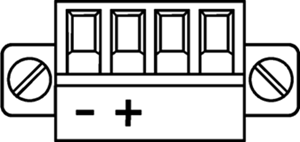
Power Connector
Phoenix MC 1,5/ 4-STF-3,81
Connector for DC-supply: 4-Pin connector (MC 1,5/ 4-STF-3,81) locked with two screws. The connector is already mounted on the power-supply delivered with each vsmSmartHub.
Power Supply
Product | Description | Item Number |
|---|---|---|
LBP-PSU (Phoenix-Plug) | 12V DC power supply, 4-Pin-Phoenix-Type | 799-0089-000 |
![]() (EN) Warning
(EN) Warning
It is understood that only the external Power-Supply-Unit (PSU) provided by Lawo, and shipped with the specific vsm device, is used for operating the product.
The provided Power-Supply-Unit is equipped with an LPS certified 12V-DC-output that is mandatory for all vsmGear products.
To feed the device via the DC input (exempt power core) it is mandatory to use a 12V power source that is certified as “SELV/LPS” (if certified according to 60950) or as “ES1/PS2(LPS)” (if certified according to 62368) “NEC Class 2” 12V power source. The UL mark is valid only with use of UL certified PSUs of categories QQGQ (UL 60950) or QQJQ (UL 62368). The supplied Lawo 12V PSU is compliant to these requirements.
![]() (F) Avertissement
(F) Avertissement
Il est entendu que seul le bloc d'alimentation externe fourni par Lawo, et livré avec le dispositif vsm spécifique, est utilisé pour faire fonctionner le produit.
Pour alimenter l'appareil via l'entrée DC, il est obligatoire d'utiliser une source d'alimentation 12V conforme aux exigences «SELV / LPS» (si certifiée selon la norme IEC 60950) ou «ES1 / PS2 (LPS)» (si certifiée selon la norme IEC 62368) Source d'alimentation 12V “NEC Classe 2”. La marque UL est seulement valable quand l'alimentation elle-même est certifiée par UL dans les catégories QQGQ (norme UL 60950) ou QQJQ (norme UL 62368). Le bloc d’alimentation Lawo 12V fourni avec l’équipement est conforme à ces exigences.
Serial Interface and Wiring
RJ45 RS422 (Standard: EIA-422) |
|
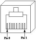
Pin | Signal description "SWAP RS422 Rx/Tx Pins = False" | Comments |
|---|---|---|
1 | NC | Internally not connected |
2 | NC | Internally not connected |
3 | Rx+ | Receive Data input |
4 | Tx+ | Transmit Data output |
5 | Tx- | Transmit Data output |
6 | Rx- | Receive Data input |
7 | NC | Internally not connected |
8 | NC | Internally not connected |
Sub-D9 male RS232 (Standard: EIA RS232D 2.1.7) |
|
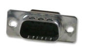
Pin | Signal description | Comments |
|---|---|---|
1 | NC | Internally not connected |
2 | RxD | Receive Data input |
3 | TxD | Transmit Data output |
4 | NC | Internally not connected |
5 | GND | Ground (shield) |
6 | NC | Internally not connected |
7 | NC | Internally not connected |
8 | NC | Internally not connected |
9 | NC | Internally not connected |
RS422
- It is necessary that twisted pair is used for Tx as well as twisted pair for Rx.
- To avoid potential difference between devices, shielded cable and shielded plugs with ground potential on both sides should be used. (Metalized plug-covers of RJ-45-plugs to touch ground-flange of RJ-45 connectors).
- RS422 (RS485) does not need any signal-ground, but ground to avoid potential difference.
- For RS422 (RS485)-traces it is best to use network cable category shielded CAT5 or higher standard (e.g. shielded CAT6/CAT7).
- vsmGear-devices are built to be used with preconfigured standard shielded 1:1 network cable (CAT5 or higher standard). If there are third party devices with other than one separated twisted pair for Tx and one for Rx, it is very important, to keep untwisted or wrong-twisted wiring as short as a possible. (Max. 1 inch/2,54 cm)
- Incorrect wiring, use of cable type, use of twisted pair and non-shielded traces can lead to shorter working distances. This can also cause slow reaction of connected devices because of high retransmissions and may even lead to strange behavior of connected devices.
- A bad connection on one of the core twisted pair traces may lead to a working device that initially works fine, but intermittently loses connection or shows strange behavior. Always use a cable-tester before installing vsm-products to ensure there is no unsuspected trouble with connected devices after installation. Also check proper wiring of wire-shield-traces.
- We suggest RS422 traces via shielded twisted pair cable should not exceed 100m (328 feet) in total length.
- Up to 32 serial devices can be used in one chain. Using more than 32 devices in one chain may work with good cabling, but is not guaranteed and therefore not recommended.
RS232
- RS232 is a single ended point-to-point signal transfer. There are only 3 traces necessary for serial data transfer, two for data (Rx and Tx), and one for signal ground.
- Tx host must be connected to Rx device and Rx host must be connected to Tx device. Signal-ground-pin must always be connected for RS232 communication on both ends.
- Because of single ended structure, the traces between host and device must be short depending on data rate used.
- The following figure shows the maximum cable-length according to the data rate.
Data-rate vs. trace-length RS232 | |
|---|---|
Max. baud | Max. length |
2.400 | 900 m |
4.800 | 300 m |
9.600 | 152 m |
19.200 | 15 m |
57.600 | 5 m |
115.200 | <2 m |
Pin @ Sub-D9 | RS232 color standard: EIA-232 |
|---|---|
1 | brown |
2 | red |
3 | orange |
4 | yellow |
5 | green |
6 | blue |
7 | violet |
8 | grey |
9 | black |
![]() (EN) Warning
(EN) Warning
It is mandatory that the RS422 connection via copper based, twisted pair network-cable (using shielded CAT 5 or higher standard, having shielded RJ45 connectors attached) and the RS232 connection via IT-certified cable is to be established within the same building and needs to follow the rules of approved certified IT equipment.
![]() (F) Avertissement
(F) Avertissement
Il est obligatoire que les connexions RS422 via câble à base de cuivre, réseau à paire torsadée (utilisant la norme CAT 5 ou supérieure, avec des connecteurs RJ45 blindés) et la connexion RS232 via un câble certifié IT doivent être établies dans le même bâtiment et doivent suivre les règles des appareils informatique certifiés et approuvés.
Ethernet Interface and Wiring
It is understood that for proper operation each SmartHub is connected to an Ethernet-switch where the individual port of the switch is set to "Auto-Negotiation".
Cette interface est utilisée comme port de communication Ethernet vers vsmStudio. Il est entendu que pour un fonctionnement correct, chaque SmartHub est connectée à un switch Ethernet dont le port individuel est réglé sur "Auto-négociation".
Pin | Signal | Color of a standard TIA-568A-shielded twisted pair patch cable (CAT5 or higher) | Scheme |
|---|---|---|---|
1 | TX+ | white/green |  |
2 | TX- | green | |
3 | RX+ | white/orange | |
4 | NC | blue | |
5 | NC | white/blue | |
6 | RX- | orange | |
7 | NC | white/brown | |
8 | NC | brown |
Notice for wiring:
- NC: No connection; does not connect to any signal or supply.
- Only use shielded CAT5 (or higher standard) -specified networkable. Refer to TIA-568A or TIA-568B for wiring.
- Do not use cable-traces longer than 100m (328ft) between the device and network-switch for 100BASE-T communication.
- Make sure to do standard wiring and use shielded RJ45-plugs for shielded cable on both ends of the line.
![]() (EN) Warning
(EN) Warning
It is mandatory, that copper based Ethernet connections (CAT 5 or higher standard, RJ45) are led inside a building to the third party-device-ethernet-switch . If the Ethernet connection needs to be led outside a building it is mandatory to use a optical fiber. Use a converter to optical fiber and connect it in a short way (inside the building) to the device.
![]() (F) Avertissement
(F) Avertissement
Il est obligatoire que les connexions Ethernet à base de cuivre (CAT 5 ou une norme supérieure, RJ45) soient installées à l'intérieur d'un bâtiment jusqu'au prochain switch Ethernet. Si la connexion Ethernet doit être dirigée à l'extérieur d'un bâtiment, utilisez un convertisseur en fibre optique et une connexion courte (à l'intérieur du bâtiment) à l'appareil.
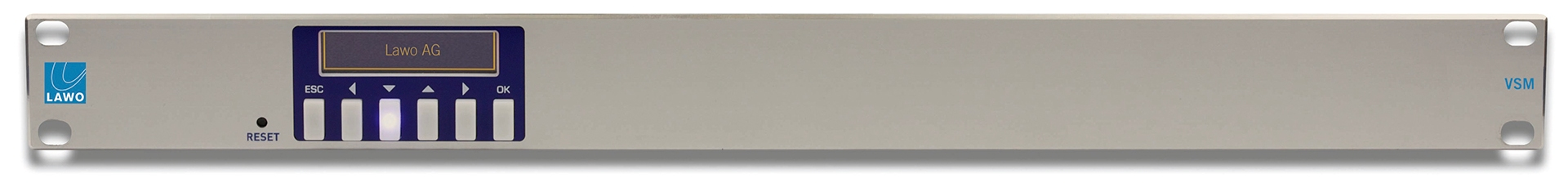
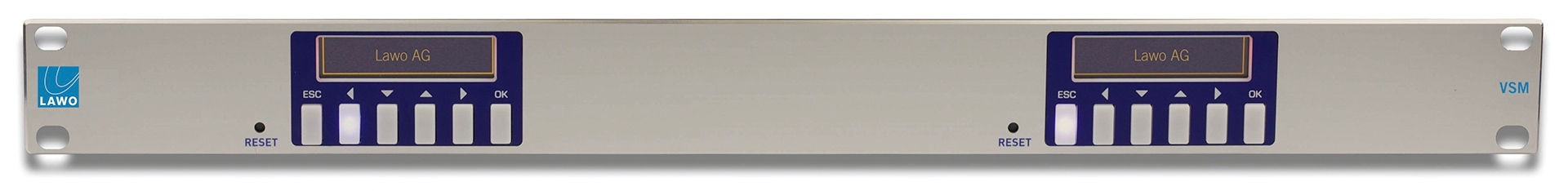
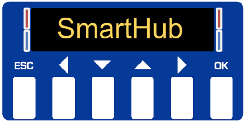
Display
Status LEDs
| Color | Meaning |
|---|---|
| Blue | Device is connected to Primary and Secondary Server. |
| Purple | Device is connected to Primary Server only. |
| Red | Device is not connected to any Server. |
Display Error Messages
| Message | Meaning |
|---|---|
| Check Network Connection | Ensure the device is physically connected via RJ45 Ethernet to your network and has a valid link. |
Lost Connection to CPU | Display unit has lost its connection to the main CPU unit. Please use the reset button located on the left below the front display to reset the whole device. |
Menu structure
The four arrow buttons allow you to navigate through the menu. With a long press on the "ESC" button a quick jump to the main infoscreen is possible. The current display version is read only.
Main Infoscreen / Screensaver
A few important settings are shown cyclical on this screen: IP Address/MAC Address, Location/Comment and the company brand. Use the Up/Down buttons to navigate through this screen. Display becomes idle after 60 seconds without using any button.
Menu
Items marked in green are writeable via vsmDiscover.
Level 1 | Level 2 | Level 3 |
|---|---|---|
| Network Settings | ||
| Server IPs | ||
| Server 1 (IP Address) | ||
| Server 2 (IP Address) | ||
| Server 3 (IP Address) | ||
| Server 4 (IP Address) | ||
| Device IP | ||
| DCHP (boolean) | ||
| IPv4 (IPAddress) | ||
| Subnet (IPAddress) | ||
| Gateway (IPAddress) | ||
| MAC (MACAddress) | ||
| DNS (String) | ||
| Serial Settings | ||
| Port xx (up to 4 ports) | ||
| Type (String) | ||
| Protocol (Enumeration) | ||
| TCP-Port (String) | ||
| Tx Idle Disconnect (Integer) | ||
| Rate Tx (B/s) (Integer) | ||
| Rate Rx (B/s) (Interger) | ||
| Baudrate (Enumeration) | ||
| DataBit (Enumeration) | ||
| StopBit (Enumeration) | ||
| Parity (Enumeration) | ||
| Swap Rx/Tx Pin (boolean), RS422 only | ||
| General Settings | ||
| Comment (String) | ||
| Location (String) | ||
| Primary (IPAddress) | ||
| Secondary (IPAddress) | ||
| General Info | ||
| Moniker (String) | ||
| Version (String) | ||
| Temperature (String) | ||
| Hardware Revision (String) | ||
| Hardware ID (String) | ||
| Software ID (String) | ||
| Serial Mode (String) | ||
| OS Version (String) |
Getting Ready for Operation
SmartHub supports up to 7 protocols and can be configured via vsmDiscover. You can find vsmDiscover in the latest VSM Release available at http://www.lawo.com/download.
The following protocols are available:
- RAW: Serial data to IP
- TunnelMode: Most commonly used for Sony MVS8000 Editor Port
- Probel-sw-p-08: Common Probel-sw-p-08 connection
- MPK-Proxy: MPK master bus
- Pesa-Proxy: Remote Control Panel (RCP) - Pesa master bus
- UMD-Proxy: Master bus for Lawo UMDs
- MI3040: MPK slave bus simulating a MI3040
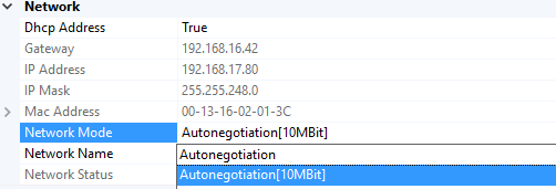
All Lawo vsmGear devices will be shipped with DHCP enabled network configuration. If you do not have a DHCP network ask your administrator for the static network settings and edit the "Network" section if required.
Do the following settings in vsmDiscover: ![]()
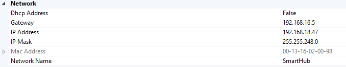
Press the "Apply" button once the settings are correctly entered. The device will automatically perform a reboot to apply the network configuration.
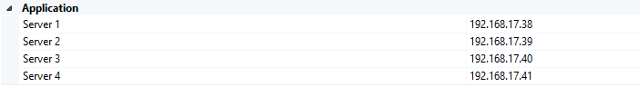
To connect the device to a vsmStudio Server (Server 1 – 4 depending on redundancy) use the "Application" section. This connection will be used by the proxy protocols and for firmware update.
Once this has been done the serial settings can be configured. Caution, after a change has been applied to the "Protocol-Name" field the device will perform a reboot automatically to load the needed driver.
Settings per Protocol
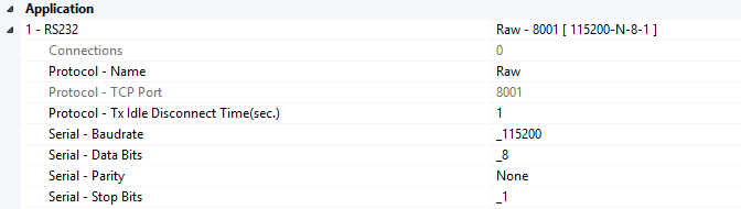
RAW
Free configurable serial interface. To connect this port with vsmStudio use the given value for "Protocol-TCP Port" below and the SmartHub IP Address. Use "Tx Idle Disconnect Time" to define how long the TCP socket should be maintained before a socket timeout occurs.
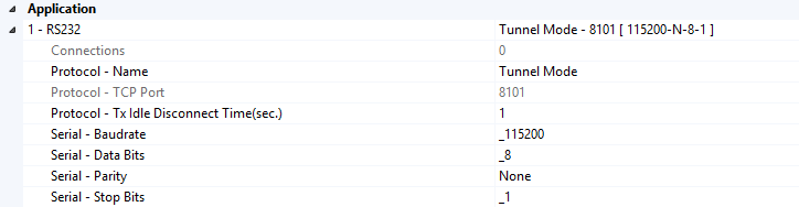
Tunnel Mode
Free configurable serial interface. To connect this port to vsmStudio read the application note for Sony MVS8000 Editor Port and use the given value for "Protocol-TCP Port" below and the SmartHub IP Address. Use "Tx Idle Disconnect Time" to define how long the TCP socket should be maintained before a socket timeout occurs.
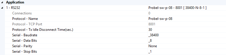
Probel-sw-p-08
Free configurable serial port to interface Probel-sw-p-08 devices. To connect this port with vsmStudio use the given value for "Protocol-TCP Port" below and the SmartHub IP Address. Use "Tx Idle Disconnect Time" to define how long the TCP socket should be maintained before a socket timeout occurs.
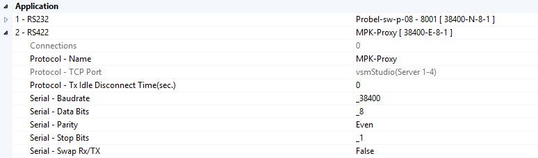
MPK-Proxy
Master bus to interface MPK devices. To connect this port with vsmStudio use Server 1-4 fields in the "Application" section. This protocol is only available for RS422 ports with preconfigured serial settings. Every reboot will discard any changes for Baudrate, Data Bits, Parity, Stop Bits and Swap Rx/Tx fields.
Verified and supported MPK devices are:
CP-310/-330-328 with BTS and Philips label
CP-3832 with Grass Valley and Philips label
CP-3864 with Philips label
CP-3020 with Philips label
UMD3A with BTS and Philips label
Up to 12 panels and 32 UMDs per Port.
Bus Limitation: Max. 2 CP38xx panels on same bus.
Pesa-Proxy
Master bus to interface Pesa panels. To connect this port with vsmStudio use Server 1-4 fields in the "Application" section. This protocol is only available for RS422 ports with preconfigured serial settings. Every reboot will discard any changes for Baudrate, Data Bits, Parity, Stop Bits and Swap Rx/Tx fields.

Verified and supported Pesa devices are:
- RCP-MLDT
- RCP-MP32
- RCP-CSD2
- RCP-48 Remote
- Panel Port Expander RCP Bus
Up to 32 panels per Port.
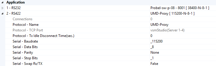
UMD-Proxy
Master bus to interface Lawo UMDs. To connect this port with vsmStudio use Server 1-4 fields in the "Application" section. This protocol is only available for RS422 ports with preconfigured serial settings. Every reboot will discard any changes for Baudrate, Data Bits, Parity, Stop Bits and Swap Rx/Tx fields.
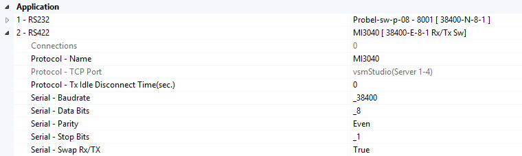
MI3040
Simulates a MI3040 General Purpose/Tally Interface. To connect this port with vsmStudio use Server 1-4 fields in the "Application" section. This protocol is only available for RS422 ports with preconfigured serial settings. Every reboot will discard any changes for Baudrate, Data Bits, Parity, Stop Bits and Swap Rx/Tx fields.
The Location and Comment fields in the "Misc" section can be set to reference the device in your environment.
![]()
Supported Baudrates:
- 1.200 Baud
- 2.400 Baud
- 4.800 Baud
- 9.600 Baud
- 14.400 Baud
- 19.200 Baud
- 28.800 Baud
- 38.400 Baud
- 57.600 Baud
- 76.800 Baud
- 115.200 Baud
- 230.400 Baud
Data Bits can either be set to "5", "6", "7" or "8", as well as Parity (Odd/Even/None) and Stop-Bits (1 or 2).
Reset the Interface
Beside the possibility to "Reset" the SmartHub via vsmDiscover (soft-Reset), there is also the possibility to assert a "Reset" hard-Reset by the Reset-knob on the lower left side next to the SmartHub-display. The Reset-knob can easily be reached with a pin or pen if needed, but is recessed to prevent accidentally assertion during normal operation. If the Reset-knob is manually asserted for a short time period, an internal reset-handler resets the main CPU, as well as the peripheral parts such as the network controller and the OLED-display-unit. Please avoid using the Reset-knob as in most cases it is not necessary. Before intending to use the Reset-knob check if the serial cabling to third party device is correct and that the third party-device is in proper working condition. Also check the serial settings applied in vsmDiscover for specific port. Make sure your network-connection to vsmStudio is established and in proper condition.
Never activate the Reset-knob while the device is in Firmware-update-mode. During firmware-update-mode, the red and blue LEDs located on the left and right within the display-unit start to flash very fast.
N'activez jamais le bouton de réinitialisation lorsque l'appareil est en mode de mise à jour du micrologiciel. Pendant le mode de mise à jour du micrologiciel, les DEL rouge et bleue situées à gauche et à droite de l'unité d'affichage se mettent à clignoter très rapidement.