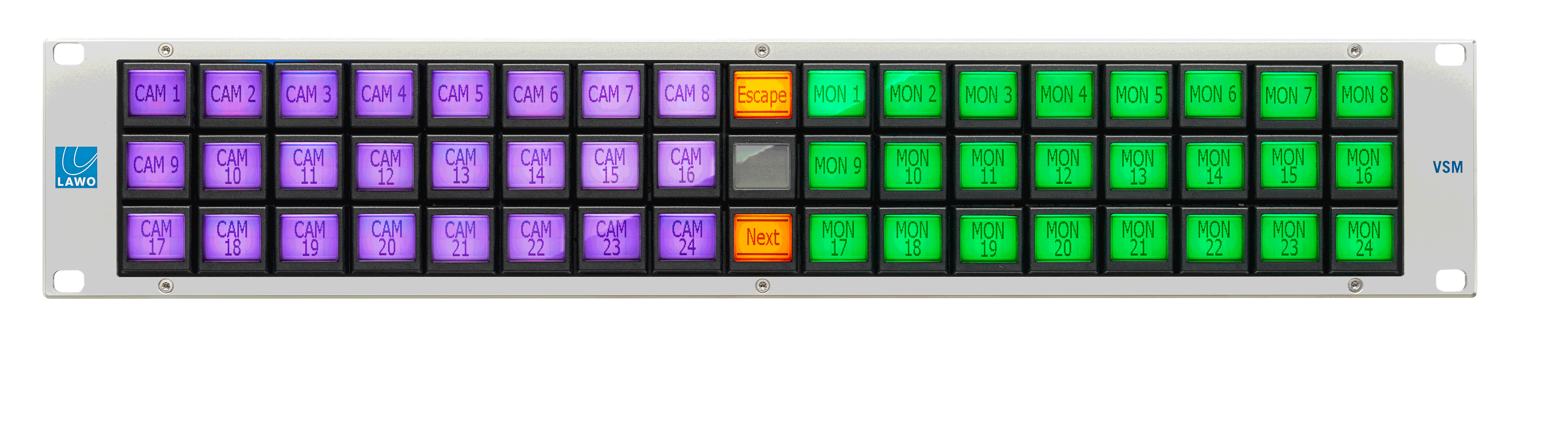
vsmLBP - LCD Pushbutton Panels
Introduction
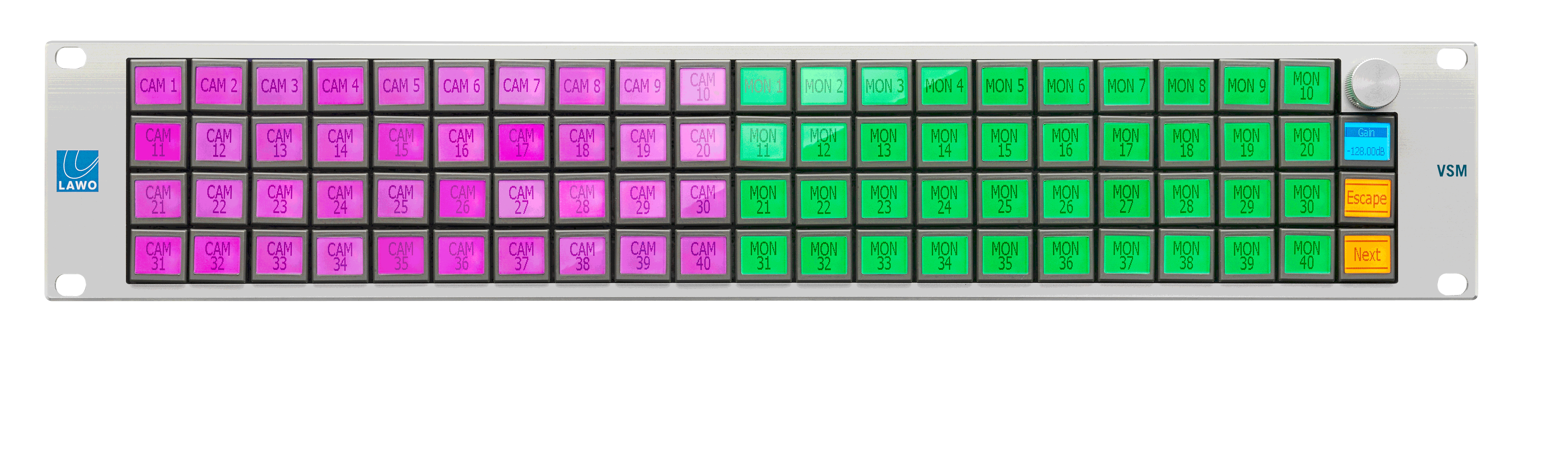
LCD Button Panels (LBP) are remote panels specifically designed for use with vsmStudio. The panels can be configured to meet every production environment’s requirement. A Single Destination, a Multiple Destination, a XY configuration or a combination of those alternatives is possible. The hardware panels provide multiple pages like the virtual panels. With the vsmStudio panel editor, LBP panels can be configured online or offline where online changes will be displayed in real-time.
The panels are connected to the vsmStudio control system via TCP/IP. The function possibilities of the LBP-series are manifold, for example they can perform routing, control devices - or signal parameters. Secondary functions enable multiple actions at one button push. With the aid of the panel editor of the vsmStudio software several panels can virtually be combined to one big panel. These features allow the implementation of every operating philosophy.
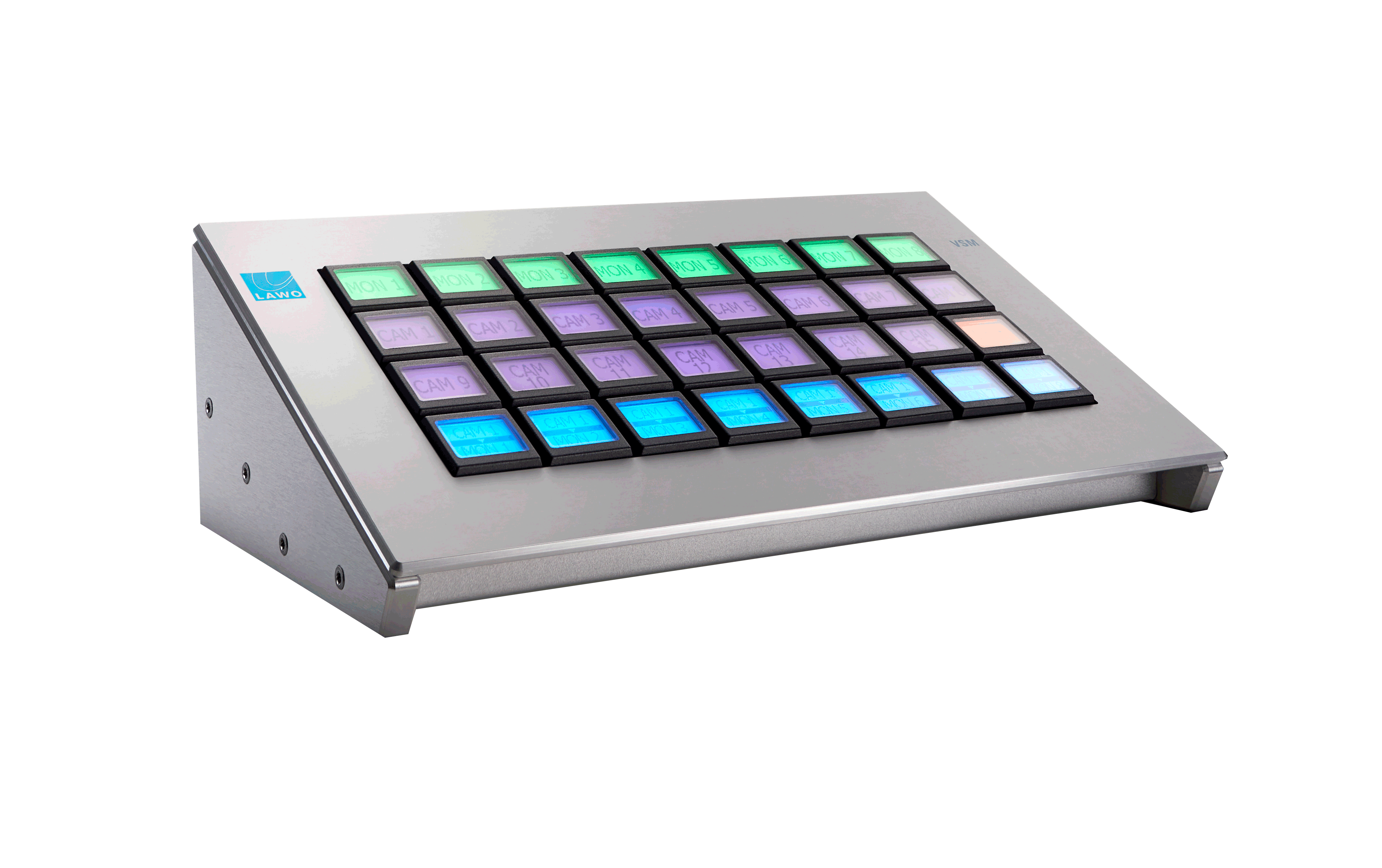
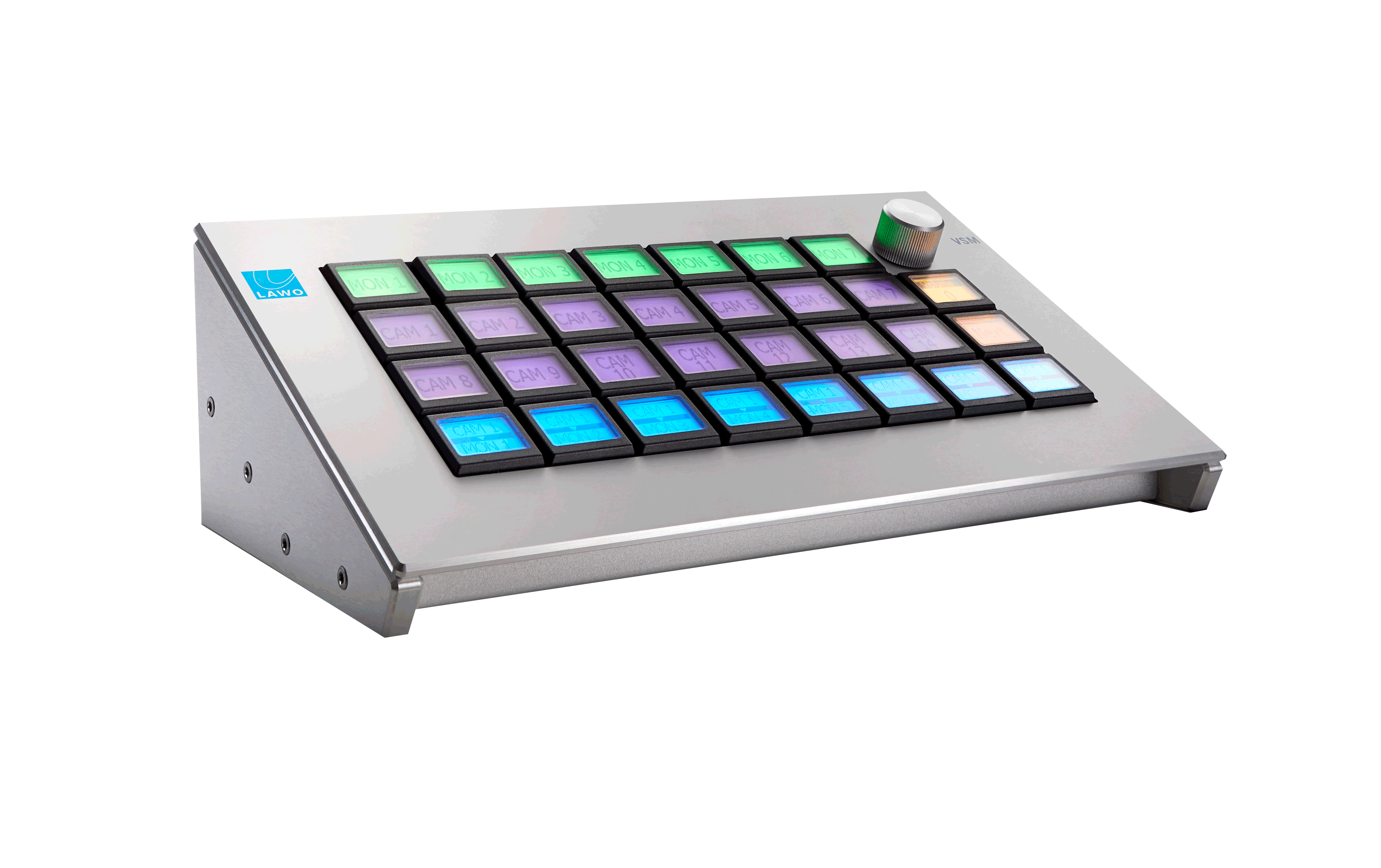
Each LBP-button integrates a Liquid Crystal Display (LCD) with R/G/B backlight enabling the operator to arrange any possible combination of functions, sources and targets across different pages. In addition to the Ethernet port every LBP provides two GPIs and two GPOs and an RS422 port (RS422 for external accessories only). The hardware panels are mounted into a solid steel coil coated housing and can be integrated into every production environment.
The LBP-panels are available in a variety of different sizes and optionally for LBP-series only with one incremental encoder instead of one LCD-button. Additionally, a 1RU incremental encoder stripe with 17 rotary encoders or an RFID Tag Reader-box can be connected through the RS422 port of each LBP-panel. All panels are to be powered by an external capsulated 12Volts DC stabilized power supply with a maximum of 3% Voltage discrepancy, a minimum current capability of 5A and external short-circuit-protection (fuse, circuit breaker or electronic short circuit-protection within the power supply).
Features
- Software configurable buttons
- Each button capable of performing single or multiple functions simultaneously
- Each panel can be configured as “single destination”, “multiple destinations”, “XY” panel or any combination of these variations
- Every LBP has two low power GPIs and GPOs
- For LBP, an optional incremental encoder can be added for e.g. parameter entry
- Every LBP is equipped with Ethernet interface
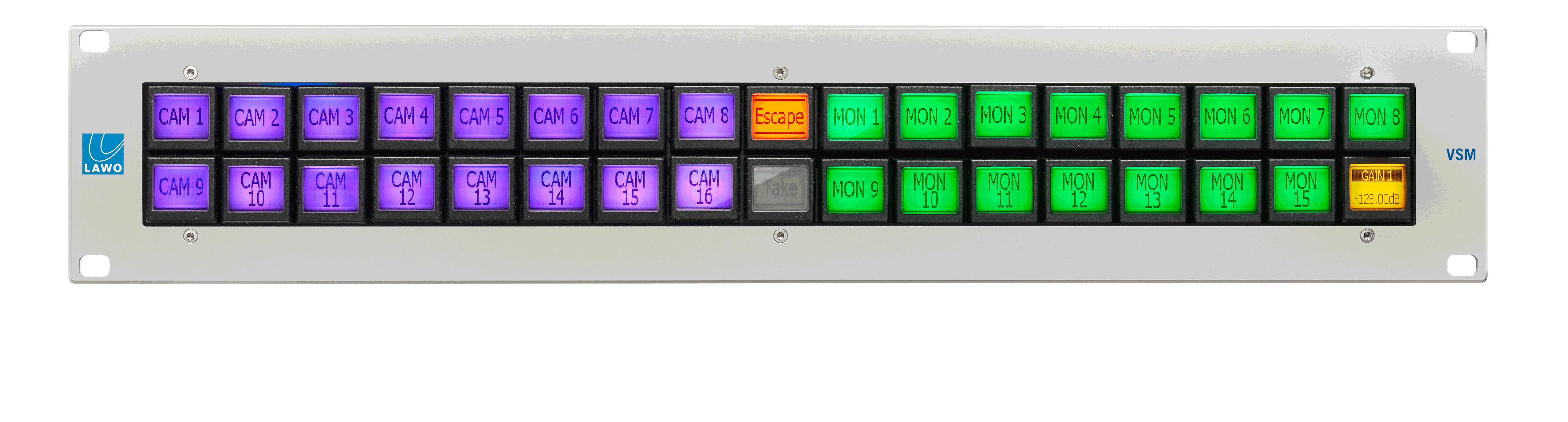
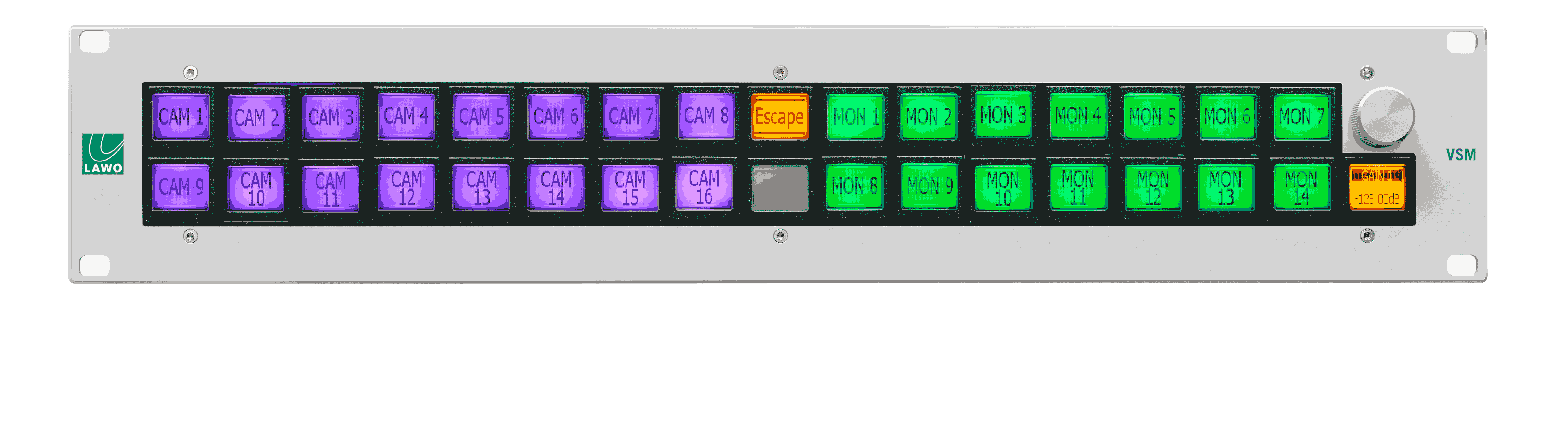
- Button functions include: select sources or targets, GPI control, parameter control, macros, go-to, take, lock, enable, escape, shift and many more
- Every LBP enables offline and online configuration. All online changes occur in ‘real-time’ which eliminates downtime
- Selected LBP without incremental encoder provides the option of being used as a “stand-alone” or “fall-back” panel to directly control a router without any router control system (SNAP-panel)
- One optional 1RU encoder-stripe with 17 incremental rotary encoders can be connected directly to each LBP via RS422
- Full colour R/G/B backlight at the LBP’s allows the choice of multiple colours for button illumination.
Technical Specifications
LBP Panels with E3 pushbuttons
vsmLBP 8
| Number of buttons | 8 LCD Buttons [E3] R/G/B-Backlight |
Options | - | |
Communication port | 1 x Ethernet | |
Dimension | 258mm x 43,7mm x 52mm (WxHxD): 1 RU/2 | |
Weight | approx. 0,5kg | |
Power-Consumption | < 20W | |
Working-Environment | 0°C-50°C non condensing humidity |

vsmLBP 17
| Number of buttons | 17 LCD Buttons [E3] R/G/B-Backlight |
Options | vsmSnap | |
Communication port | 1 x Ethernet | |
Dimension | 483mm x 43,7mm x 53,1mm (WxHxD): 1 RU | |
Weight | approx. 1,0kg | |
Power-Consumption | < 20W | |
Working-Environment | 0°C-50°C non condensing humidity |
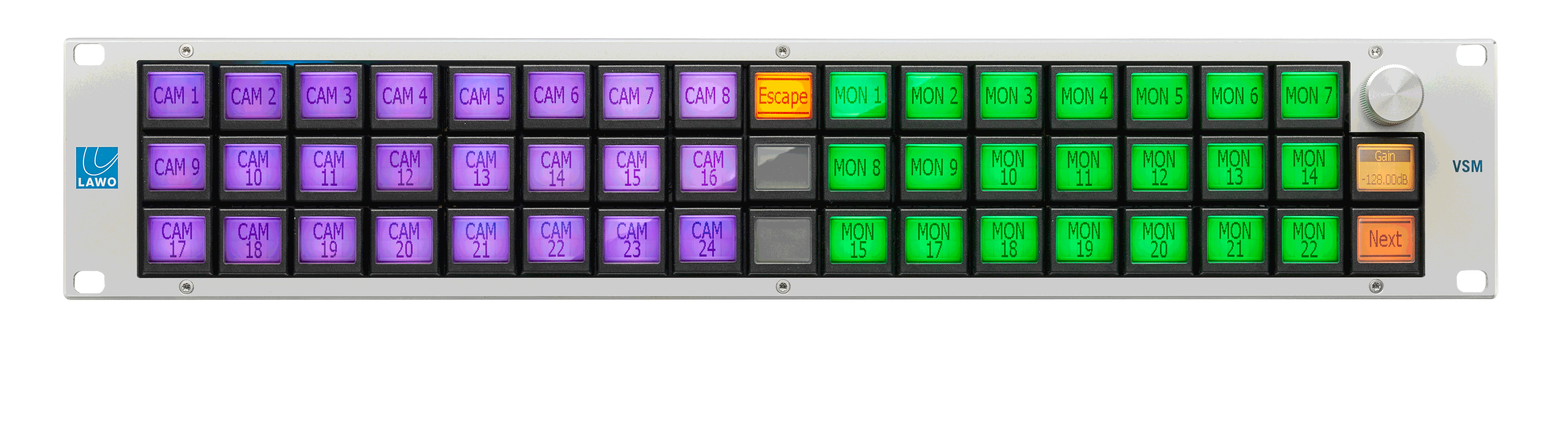
vsmLBP 16e
| Number of buttons | 16 LCD Buttons [E3] R/G/B-Backlight + 1 Encoder |
Options | - | |
Communication port | 1 x Ethernet | |
Dimension | 483mm x 43,7mm x 53,1mm (WxHxD): 1 RU | |
Weight | approx. 1,0kg | |
Power-Consumption | < 20W | |
Working-Environment | 0°C-50°C non condensing humidity |
vsmLBP 24
| Number of buttons | 24 LCD Buttons [E3] R/G/B-Backlight |
Options | - | |
Communication port | 1 x Ethernet | |
Dimension | 258mm x 88mm x 53mm (WxHxD): 2 RU/2 | |
Weight | approx. 0,8kg | |
Power-Consumption | < 20W | |
Working-Environment | 0°C-50°C non condensing humidity |

vsmLBP 32
| Number of buttons | 32 LCD Buttons [E3] R/G/B-Backlight |
Options | - | |
Communication port | 1 x Ethernet | |
Dimension | 240mm x 111,5mm x 53mm (WxHxD): 2,5 RU/2 | |
Weight | approx. 1,0kg | |
Power-Consumption | < 20W | |
Working-Environment | 0°C-50°C non condensing humidity |
vsmLBP 32-DT
| Number of buttons | 32 LCD Buttons [E3] R/G/B-Backlight |
Options | vsmSnap | |
Communication port | 1 x Ethernet | |
Dimension | 256mm x 83,6mm x 140,6mm (WxHxD) | |
Weight | approx. 1,8 kg | |
Power-Consumption | < 20W | |
Working-Environment | 0°C-50°C non condensing humidity |
vsmLBP 31e-DT
| Number of buttons | 31 LCD Buttons [E3] R/G/B-Backlight + 1 Encoder |
Options | - | |
Communication port | 1 x Ethernet | |
Dimension | 256mm x 83,6mm x 140,6mm (WxHxD) | |
Weight | approx. 1,8 kg | |
Power-Consumption | < 20W | |
Working-Environment | 0°C-50°C non condensing humidity |
vsmLBP 34
| Number of buttons | 34 LCD Buttons [E3] R/G/B-Backlight |
Options | vsmSnap | |
Communication port | 1 x Ethernet | |
Dimension | 483mm x 88mm x 53,2mm (WxHxD): 2 RU | |
Weight | approx. 1,4kg | |
Power-Consumption | < 20W | |
Working-Environment | 0°C-50°C non condensing humidity |
vsmLBP 33e
| Number of buttons | 33 LCD Buttons [E3] R/G/B-Backlight + 1 Encoder |
Options | - | |
Communication port | 1 x Ethernet | |
Dimension | 483mm x 88mm x 68,2mm (WxHxD): 2 RU | |
Weight | approx. 1,4kg | |
Power-Consumption | < 20W | |
Working-Environment | 0°C-50°C non condensing humidity |
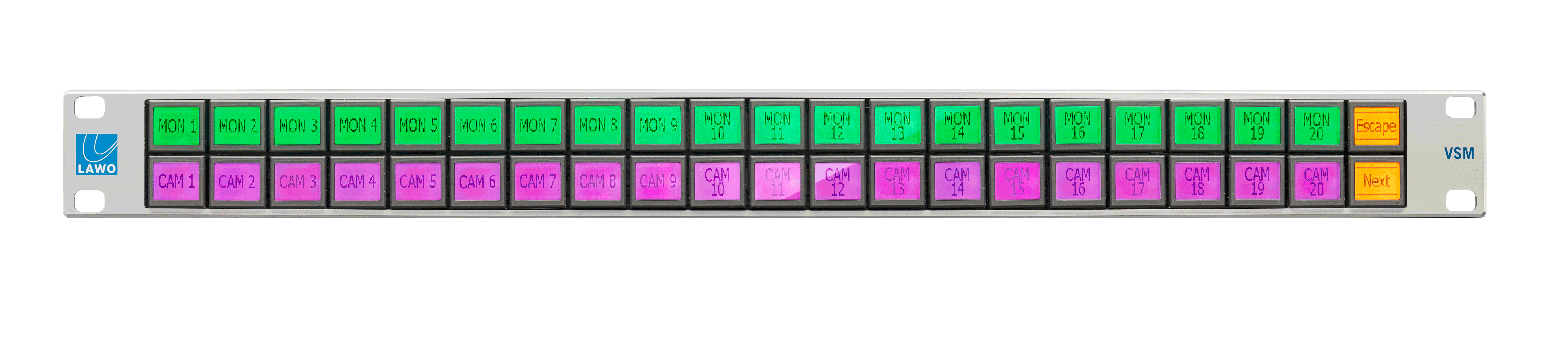
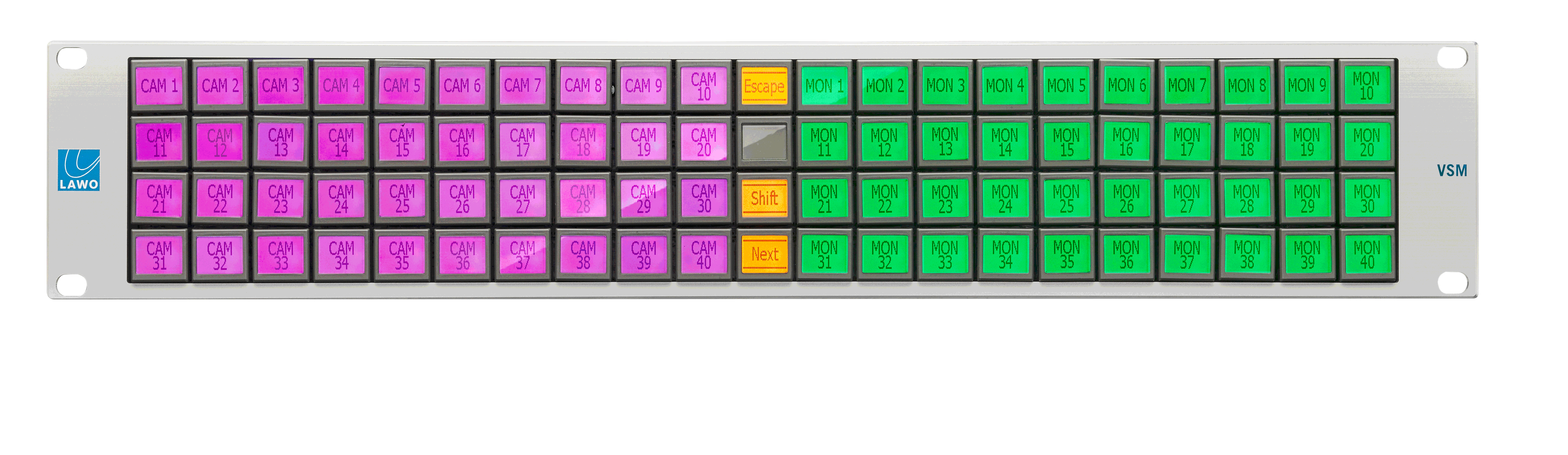
vsmLBP 51
| Number of buttons | 51 LCD Buttons [E3] R/G/B-Backlight |
Options | vsmSnap | |
Communication port | 1 x Ethernet | |
Dimension | 483mm x 88mm x 52,8mm (WxHxD): 2 RU | |
Weight | approx. 1,7kg | |
Power-Consumption | < 20W | |
Working-Environment | 0°C-50°C non condensing humidity |
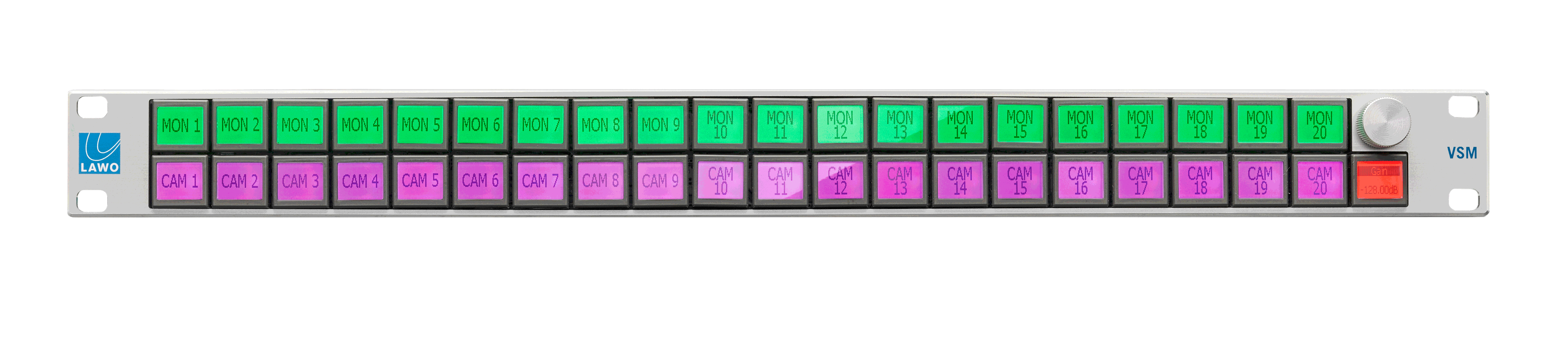
vsmLBP 50e
| Number of buttons | 50 LCD Buttons [E3] R/G/B-Backlight + 1 Encoder |
Options | - | |
Communication port | 1 x Ethernet | |
Dimension | 483mm x 88mm x 68,3mm (WxHxD): 2 RU | |
Weight | approx. 1,7kg | |
Power-Consumption | < 20W | |
Working-Environment | 0°C-50°C non condensing humidity |
vsmLBP 17x2
| Number of buttons | 2x17 LCD Buttons [E3] R/G/B-Backlight |
Options | - | |
Communication port | 2 x Ethernet | |
Dimension | 915mm x 43mm x 53,3mm (WxHxD) (deskmount only) | |
Weight | approx. 1,9kg | |
Power-Consumption | < 20W per power-supply (2x) | |
Working-Environment | 0°C-50°C non condensing humidity |
vsmLBP 34V
| Number of buttons | 34 LCD Buttons [E3] R/G/B-Backlight |
Options | - | |
Communication port | 1 x Ethernet | |
Dimension | 65,1mm x 483mm x 59mm (WxHxD) | |
Weight | approx. 1,4kg | |
Power-Consumption | < 20W | |
Working-Environment | 0°C-50°C non condensing humidity |
vsmLBP 39V
| Number of buttons | 39 LCD Buttons [E3] R/G/B-Backlight |
Options | - | |
Communication port | 1 x Ethernet | |
Dimension | 92mm x 355,50mm x 59mm (WxHxD) | |
Weight | approx. 1,3kg | |
Power-Consumption | < 20W | |
Working-Environment | 0°C-50°C non condensing humidity |
vsmLBP 51V
| Number of buttons | 51 LCD Buttons [E3] R/G/B-Backlight |
Options | - | |
Communication port | 1 x Ethernet | |
Dimension | 88,3mm x 483mm x 59mm (WxHxD) | |
Weight | approx. 1,7kg | |
Power-Consumption | < 20W | |
Working-Environment | 0°C-50°C non condensing humidity |
LBP Panels with NKK pushbuttons
vsmLBP 42
| Number of buttons | 42 LCD Buttons [NKK] R/G/B-Backlight |
Options | - | |
Communication port | 1 x Ethernet | |
Dimension | 483mm x 43,7mm x 53,3mm (WxHxD): 1 RU | |
Weight | approx. 1,3kg | |
Power-Consumption | < 20W | |
Working-Environment | 0°C-50°C non condensing humidity |
vsmLBP 41e
| Number of buttons | 41 LCD Buttons [NKK] R/G/B-Backlight + 1 Encoder |
Options | - | |
Communication port | 1 x Ethernet | |
Dimension | 483mm x 43,7mm x 53,1mm (WxHxD): 1 RU | |
Weight | approx. 1,3kg | |
Power-Consumption | < 20W | |
Working-Environment | 0°C-50°C non condensing humidity |
vsmLBP 84
| Number of buttons | 84 LCD Buttons [NKK] R/G/B-Backlight |
Options | - | |
Communication port | 1 x Ethernet | |
Dimension | 483mm x 87,2mm x 56,5mm (WxHxD): 2 RU | |
Weight | approx. 2,1kg | |
Power-Consumption | < 20W | |
Working-Environment | 0°C-50°C non condensing humidity |
vsmLBP 83e
| Number of buttons | 83 LCD Buttons [NKK] R/G/B-Backlight + 1 Encoder |
Options | - | |
Communication port | 1 x Ethernet | |
Dimension | 483mm x 87,2mm x 70,5mm (WxHxD): 2 RU | |
Weight | approx. 1,7kg | |
Power-Consumption | < 20W | |
Working-Environment | 0°C-50°C non condensing humidity |
![]() (E) Warning / (F) Avertissement
(E) Warning / (F) Avertissement
Please click on the link below to open the booklet as a pdf:
![]() (E) ATTENTION
(E) ATTENTION
DO NOT spill liquids into any system components!
DO NOT clean the front panels or operational surfaces with sharp instruments.
![]() (F) ATTENTION
(F) ATTENTION
NE PAS renverser de liquides dans les composants du système!
NE PAS nettoyer les panneaux avant ou les surfaces opérationnelles avec des instruments pointus.
![]() (E) IMPORTANT NOTE
(E) IMPORTANT NOTE
General Cleaning / Disinfecting Requirements
Lawo hardware products are made from a variety of different materials, and each material might have specific cleaning requirements. Therefore, a general allowance for the disinfection of product surfaces with disinfectants containing alcohol cannot be given.
Our front panels and operational surfaces are not entirely approved for treatment with chemical cleaning agents and disinfectants. Component surfaces, buttons and electronics can be permanently damaged by treatment with such agents and the lifespan can be dramatically shortened. Please note that some substances can lead to discoloration of surfaces.
Lawo is not responsible for damage caused by the unauthorized use of disinfectants on our products and surfaces. Damages caused by unspecified treatment of modules and components are not covered by regular or extended warranties or SLA regulations.
This is a general instruction and recommendation for cleaning that applies to all Lawo products:
- Before cleaning the device, unplug all external power sources.
- Clean the device with a soft cloth, dipped lightly in warm to hot soapy water.
- Do not use any liquid cleaning agents or spray cleaners that may contain flammable materials.
- Do not get moisture into any openings.
- Do not use aerosol sprays, bleaches, or abrasives.
- Do not spray cleaners directly onto the item.
The above information and our technical application advice are given to the best of our knowledge.
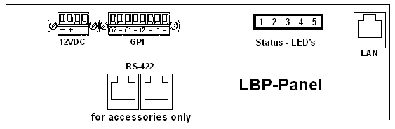
Status LEDs
Rearview
| |||
| LED | Color | Status | Meaning |
|---|---|---|---|
| 1 | RGB | Blue, Steady on | internal serial I/O controller OK, green: serial TX, red: serial RX. |
| 2 | RGB | Red Pulse | no connection to the network |
| Red Fast Blink | device in bootloader-mode | ||
| Yellow Pulse | network connection established | ||
| Blue Pulse | connected to vsmStudio | ||
| 3 | Green | Steady on | processor core-voltage OK |
| 4 | Green | Steady on | internal I/O-voltage OK |
| 5 | Orange | Blink | physical LAN connection / TCP/IP-data-transfer |
Buttons
LCD-Pushbuttons [E3]
Each pushbutton “SL 6432” made by “E3” has a mechanical size of (X x Y) 24.5mm x 23.5mm with a screen size (X x Y) of 17.26mm x 12.14mm. The resolution is (X x Y) 64x32 pixel with a pixel-dot-size of (X x Y) 0.25mm x 0.36mm.
The LCD backlight colour is R/G/B, so basically all colours desired can be used.
The key stroke of the tactile buttons is about 2.0mm +/-0.1mm using an operation force of approximately 1.3N +/-0.2N. Button-spacing of LBP-panel is (X x Y) 25,4mm x 24,13mm.
All E3-buttons are placed on the PCB by sockets, so they can easily be exchanged, if damaged or worn out. The buttons can even be exchanged without powering down the LBP-panel. After replacing the button without power-down, it might take view minutes until the button shows the right backlight colour as well as the desired button-label on the LCD.
LCD-Pushbuttons [NKK]
Each compact LCD pushbutton “IS15DSBFP4RGB” made by “NKK” has a mechanical size of (X x Y) 19mm x 18mm with a screen size (X x Y) of 12.78mm x 8.3mm. The resolution is (X x Y) 64x32 pixel with a pixel-dot-size of (X x Y) 0.18mm x 0.24mm.
The LCD backlight colour is R/G/B, so basically all colours desired can be used.
The key stroke of the tactile buttons is about 1.8mm +/-0.1mm using an operation force of approximately 1.7N +/-0.5N. Button-spacing of LBP-panel is (X x Y) 20,32mm x 19,05mm.
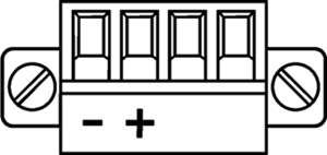
Power Connectors and Wiring
Phoenix MC 1,5/ 4-STF-3,81
Connector for 12 V DC-supply: 4-Pin connector (MC 1,5/ 4-STF-3,81) locked with two screws, mounted on power-supplies delivered with each LBP panel except for vsmLBP 31e-DT/ vsmLBP32-DT.
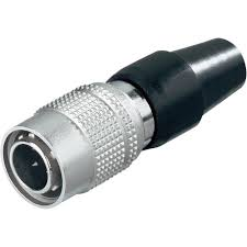
Hirose HR10A-7P-4P
Alternative connector (desktop panels only) for 12 V DC supply: 4-pin Hirose HR10A-7P-4P locked bayonet joint compact connector for better cable traction relief, mounted on power-supplies delivered with each LBP 31e-DT/ LBP32-DT panel.
| Pin | Signal |
|---|---|
| 1 | GND |
| 2 | GND |
| 3 | +12V |
| 4 | +12V |
Power Supply
| Product | Description | Item Number |
|---|---|---|
| LBP-PSU (Phoenix-Plug) | 12V DC power supply, 4-Pin-Phoenix-Type | 799-0089-000 |
| LBP-DT-PSU (Hirose-Plug) | 12V DC power supply, 4-Pin-Hirose-Type (For use with DESKTOP-Panles only) | 799-0090-000 |
![]() (EN) Warning
(EN) Warning
It is understood that only the external Power-Supply-Unit (PSU) provided by Lawo, and shipped with the specific vsm device, is used for operating the product.
To feed the device via the DC input it is mandatory to use a 12V power source that is certified as “SELV/LPS” (if certified according to 60950) or as “ES1/PS2(LPS)” (if certified according to 62368) “NEC Class 2” 12V power source. The UL mark is valid only with use of UL certified PSUs of categories QQGQ (UL 60950) or QQJQ (UL 62368). The supplied Lawo 12V PSU is compliant to these requirements.
![]() (F) Avertissement
(F) Avertissement
Il est entendu que seul le bloc d'alimentation externe fourni par Lawo, et livré avec le dispositif vsm spécifique, est utilisé pour faire fonctionner le produit.
Pour alimenter l'appareil via l'entrée DC, il est obligatoire d'utiliser une source d'alimentation 12V conforme aux exigences «SELV / LPS» (si certifiée selon la norme IEC 60950) ou «ES1 / PS2 (LPS)» (si certifiée selon la norme IEC 62368) Source d'alimentation 12V “NEC Classe 2”. La marque UL est seulement valable quand l'alimentation elle-même est certifiée par UL dans les catégories QQGQ (norme UL 60950) ou QQJQ (norme UL 62368). Le bloc d’alimentation Lawo 12V fourni avec l’équipement est conforme à ces exigences.
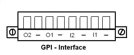
GPI/O Interface and Wiring
Connector for rear GPI/O interface: 8-Pin connector locked with two screws (MC 1,5/ 8-STF-3,81)
Separate plug not included for standard LBP delivery.
Each LBP panel features two dry relays-outputs and 2 opto-coupled TTL-inputs.
| |||||||
| O2 | - | O1 | - | I2 | - | I1 | - |
|---|---|---|---|---|---|---|---|
Dry Relay | Dry Relay | Input/GND [0...5 VDC] | Input/GND [0...5 VDC] | ||||
| Out No. 2 | Out No. 1 | In No. 2 | In No. 1 | ||||
The built-in GPI inputs follow PS1 (electrical power source class1).
The GPI input will not allow power to exceed 1W by the device itself.
- Open circuit voltage GPI input: approx. 3,8V DC, max. 5V DC
- Short circuit current GPI input: approx. 8mA
- Loaded circuit current with externally 5V (PS1) supplied: approx. 12mA
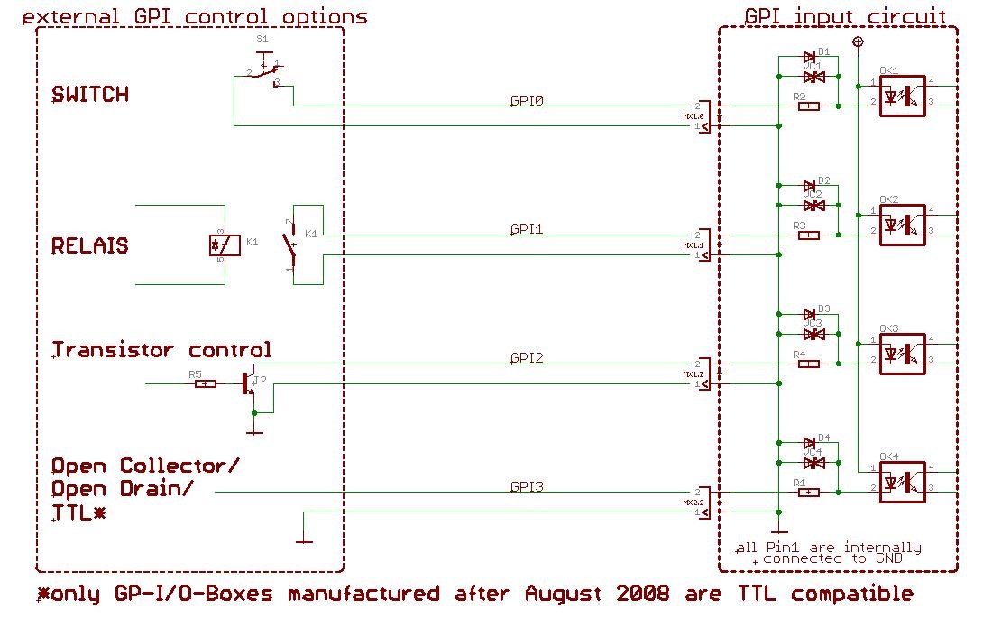
GPI - General Purpose Input
This Interface is a small signal interface only, and uses same ground potential.
The GPI DC TTL Inputs are able to “set” a readable input by either shorting the input to ground, or by supplying any 5 VDC-voltage and undershooting 2,3 VDC respective to ground.
We suggest using the separate stand-alone vsmGPIO-unit for switching higher current or reading inputs up to 12VDC.
![]() (EN) Warning
(EN) Warning
It is understood that if supplying any external voltage (DC only) to the GPI input, it is never to exceed 5V DC rms and must also follow the PS1-rules (b-IEC 62368-1) to never source more than 15W. Check polarity if external voltage is supplied.
Always connect GPI input-ground to external supply-ground! Never apply any AC-voltage to the GPI inputs!
Cette interface n'est qu'une interface basse tension, faible courant.
Les entrées GPI DC TTL sont capables de "régler" une entrée lisible soit en court-circuitant l'entrée à la terre, soit en fournissant une tension de 5 V DC et une sous-tension de 2,3 V DC respectivement à la terre.
Nous suggérons d'utiliser l'unité autonome séparée vsmGPIO pour commuter un courant plus élevé ou lire des entrées jusqu'à 12 V DC.
![]() (F) Avertissement
(F) Avertissement
Il est entendu que si une tension externe (DC uniquement) est fournie à l'entrée GPI, elle ne doit jamais dépasser 5V DC rms (valeur efficace) et doit également suivre les règles PS1 (norme b-IEC 62368-1) pour ne jamais fournir plus de 15W. Vérifiez la polarité si une tension externe est fournie.
Toujours connecter la masse de l'entrée GPI à la masse de l'alimentation externe ! Ne jamais appliquer de tension AC aux entrées GPI!
Possible GPI Input wiring and control options
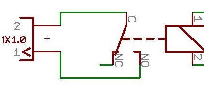
GPO - General Purpose Output
![]() (EN) Warning
(EN) Warning
To maintain the lifespan of the internal relay of the LBP, do not exceed 12VDC/50mA for each relay-contact.
The external supply-source being used for interfacing the LBP relay-contacts must also follow the PS1-rules (b-IEC 62368-1) to never source more than 15W.
Les GPO « sorties » sont des contacts de relais secs. Ils ne sont connectés en interne à aucune alimentation ou terre. L’utilisateur doit fournir une source d’alimentation externe qui suit les règles PS1 (norme b-IEC 62368-1) pour l’utilisation.
![]() (F) Avertissement
(F) Avertissement
Pour prolonger la durée de vie du relais interne du LBP, ne dépassez pas 12VDC/50mA pour chaque sortie relais.
L’alimentation externe utilisée pour l’interfaçage des contacts relais LBP doit également suivre les règles PS1 (norme b-IEC 62368-1) pour ne jamais s’approvisionner plus de 15W.
GPO contact-wiring “dry relay output”
Serial Interface and Wiring
Connector for data drive for external accessories
- 1 x RS422 via RJ45 connector
- 1 x RS422 (loop through) via RJ45 connector
- Serial Baud Rate will be configured automatically by the device to 115200 Baud
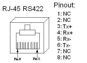
RS422 is a differential signal transfer. Each Tx and each Rx line has both a positive and a negative pole, therefore it is absolutely necessary to use a twisted pair cable. External accessory connections can easily be done by preconfigured standard shielded network cable (CAT5 or higher standard). To avoid potential difference between devices, shielded cable and shielded plugs with ground potential on both sides must be used. (Metalized plug-covers of RJ-45-plugs to touch ground-flange of RJ-45 connectors). Wrong wiring, wrong cables, wrong use of twisted pair and non-shielded traces lead to short working distances. Bad connection at one of the core in twisted pair traces may lead to a working unit, which seems to be working fine, but sometimes loses connection or showing strange behaviour. Always use a cable-tester before installing vsmGear-products to make sure, that there will be no unsuspected trouble with connected devices. Also check proper wiring of wire-shield-traces. We recommend RS422 traces via shielded twisted pair cable not to exceed 100m (328 feet) in total length.
![]() (EN) Warning
(EN) Warning
It is mandatory, that copper based Serial RS422-connections between LBPs and vsm accessories (e.g. ENC17) are established within the same building using shielded CAT 5 or higher standard, having shielded RJ45 connectors attached.
![]() (F) Avertissement
(F) Avertissement
Il est obligatoire que les connexions série RS422 en cuivre entre les LBP et les accessoires vsm (par exemple ENC17) soient établies à l'intérieur du même bâtiment en utilisant une norme CAT 5 ou supérieure, avec des connecteurs RJ45 blindés.
Ethernet Interface and Wiring
Ethernet Communication Port to vsmStudio
Port de communication Ethernet vers vsmStudio
Cette interface est utilisée comme port de communication Ethernet vers vsmStudio. Il est entendu que pour un fonctionnement correct, chaque LBP est connectée à un switch Ethernet dont le port individuel est réglé sur "Auto-négociation".
| Pin | Signal | Color of a standard TIA-568A-shielded twisted pair patch cable (CAT5 or higher) | Scheme |
|---|---|---|---|
| 1 | TX+ | white/green |
|
| 2 | TX- | green | |
| 3 | RX+ | white/orange | |
| 4 | NC* | blue | |
| 5 | NC* | white/blue | |
| 6 | RX- | orange | |
| 7 | NC* | white/brown | |
| 8 | NC* | brown |
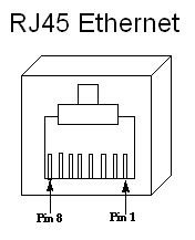
- NC: no connection; do not connect to any signal or supply
- Only use shielded CAT5 (or higher standard) -specified networkable. Refer to TIA-568A or TIA-568B for wiring.
- Do not use cable-traces longer than 100m (328ft) between the device and network-switch for 100BASE-T communication.
- Make sure to keep to wiring standards and use shielded RJ45-plugs for shielded cable on both ends of the line.
![]() (EN) Warning
(EN) Warning
It is mandatory, that copper based Ethernet connections (CAT 5 or higher standard, RJ45) are led inside a building to the third party-device-ethernet-switch . If the Ethernet connection needs to be led outside a building it is mandatory to use a optical fiber. Use a converter to optical fiber and connect it in a short way (inside the building) to the device.
![]() (F) Avertissement
(F) Avertissement
Il est obligatoire que les connexions Ethernet à base de cuivre (CAT 5 ou une norme supérieure, RJ45) soient installées à l'intérieur d'un bâtiment jusqu'au prochain switch Ethernet. Si la connexion Ethernet doit être dirigée à l'extérieur d'un bâtiment, utilisez un convertisseur en fibre optique et une connexion courte (à l'intérieur du bâtiment) à l'appareil.
Getting Ready for Operation
On startup all LBP Panels show the same device information on the first 6 buttons:
- Device Monitor
- Firmware Version
- Panel ID
- IP Address
- MAC Address.
If the device has no physical link to the network, it will show “no network” status below the IP Address. Thus there are no rotary hex encoders on the rear side of the device to configure the Panel ID, a long press on the Panel ID button will switch to a Panel ID configuration screen as long the device is not connected to any vsmStudio.
All Lawo devices will be shipped with DHCP enabled network configuration. If you don’t have a DHCP network ask your administrator for static network settings and edit the “Network” section if required.
Do the following settings in VSM Discover ![]() :
:
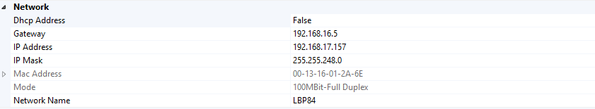
In vsmDiscover, press the “Apply” button in vsmDiscover if you are sure you have entered the settings correctly. The device will automatically perform a reboot to apply the network configuration.
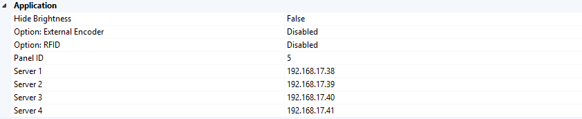
To connect the device to vsmStudio, edit the Server 1 - 4 and Panel ID in the “Application” section. There is also a possibility to connect an external serial device like an ENC17 or a RF-ID-Tag Reader. Please use the “Option: External Encoder” or “Option: RFID” field to enable this feature. A software reset is necessary for proper working external serial interface. Additional information can be found at VSM-LBP Accessories User Manual.
The Location and Comment fields in the “Misc” section can be set to easily allocate the device in your environment.

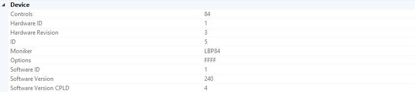
Additional read-only status and device information from vsmDiscover: