vsmUMD - Under Monitor Display
Introduction
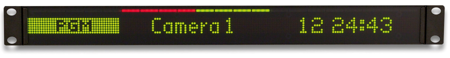
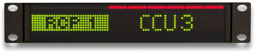
The vsmUMD Under Monitor Display displays information such as labels and tally quickly, clearly and precisely. The UMD layout can be freely configured using vsmStudio and the assigned IDs. The special surface of the UMD modules reduces finger prints and reflections and prevents from visual irritations. Text can be displayed in variable sizes, character sets, centred and inverse. Four external Tally, hardware inputs can be used for individually customized messages to be displayed during stand-alone use.
Two different UMD types are available:
- a 19-inch UMD-SD with a resolution of 170*7 pixels as graphical matrix, devidable into 16 definable segments.
- a half 19-inch UMD-SD with a resolution of 80*7 pixels as graphical matrix, devidable into 8 definable segments..
Each of these segments can be labelled and also display red, green and yellow Tally.
Technical Specification
vsmUMD SD 19"
| Number of pixels | 170x7 (X/Y) + 1 Line of red/green/yellow-Tally |
Communication port | RS422 (Ethernet communication via SmartHub) | |
Dimensions | 483mm x 43,7mm x 33,2mm (WxHxD): 1RU | |
Weight | approx. 0,7KG | |
Power-Consumption | <20W | |
Working-Environment | 0°C-50°C non-condensing humidity |
vsmUMD SD ½-19"
| Number of pixels | 80x7 (X/Y) + 1 Line of red/green/yellow-Tally |
Communication port | RS422 (Ethernet communication via SmartHub) | |
Dimensions | 260mm x 43,7mm x 33,2mm (WxHxD): 1RU/2 | |
Weight | approx. 0,4KG | |
Power-Consumption | <20W | |
Working-Environment | 0°C-50°C non-condensing humidity |
Operating Conditions
This device is built to be used in a non-condensing environment within a temperature range of 0-50°C. Under or overshooting this working temperature range may cause fast aging of components or even malfunction of the whole device.
Spillage of any liquids e.g. coffee, coke, water... onto/into the device may cause damage.
The storage temperature of the device must be within -20°C to 60°C with a maximum of 75% non-condensing relative humidity at 60°C @ 0VDC supply-voltage.
DO NOT throw, drop or bend the unit and make sure that there is no strong permanent mechanical pressure on any side of the housing at any time.
![]() (E) Warning / (F) Avertissement
(E) Warning / (F) Avertissement
Please click on the link below to open the booklet as a pdf:
![]() (E) ATTENTION
(E) ATTENTION
DO NOT spill liquids into any system components!
DO NOT clean the front panels or operational surfaces with sharp instruments.
![]() (F) ATTENTION
(F) ATTENTION
NE PAS renverser de liquides dans les composants du système!
NE PAS nettoyer les panneaux avant ou les surfaces opérationnelles avec des instruments pointus.
![]() (E) IMPORTANT NOTE
(E) IMPORTANT NOTE
General Cleaning / Disinfecting Requirements
Lawo hardware products are made from a variety of different materials, and each material might have specific cleaning requirements. Therefore, a general allowance for the disinfection of product surfaces with disinfectants containing alcohol cannot be given.
Our front panels and operational surfaces are not entirely approved for treatment with chemical cleaning agents and disinfectants. Component surfaces, buttons and electronics can be permanently damaged by treatment with such agents and the lifespan can be dramatically shortened. Please note that some substances can lead to discoloration of surfaces.
Lawo is not responsible for damage caused by the unauthorized use of disinfectants on our products and surfaces. Damages caused by unspecified treatment of modules and components are not covered by regular or extended warranties or SLA regulations.
This is a general instruction and recommendation for cleaning that applies to all Lawo products:
- Before cleaning the device, unplug all external power sources.
- Clean the device with a soft cloth, dipped lightly in warm to hot soapy water.
- Do not use any liquid cleaning agents or spray cleaners that may contain flammable materials.
- Do not get moisture into any openings.
- Do not use aerosol sprays, bleaches, or abrasives.
- Do not spray cleaners directly onto the item.
The above information and our technical application advice are given to the best of our knowledge.
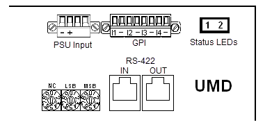
Status LEDs
Rear-view
 | |||
| LED | Color | Status | Meaning |
|---|---|---|---|
| 1 | Red | blink | Life-pulse/Incoming data |
| 2 | Green | steady on | internal voltage OK |
Addressing the UMDs
Each UMD has rotary encoders on the rear side of the UMD for applying a unique address in each RS422-chain. The address of the panel can be adjusted using a small-tip screwdriver to turn the switches.

Valid addressing for each unique UMD can be done between 0...EF (hex) which will be 0...239 (dec).
Mounting UMDs
![]() (EN) Warning
(EN) Warning
vsmUMD modules must only be installed up to a maximum height of 2m (mounting height: max. 2m).
If using “alternative mounting" instead of the standard rackmount option, it is mandatory to only use certified mounting equipment and screws. It is mandatory to use M4-type screws made of steel with a length reaching into the UMD of maximum 10mm.
A minimum of 2 screws is mandatory for mounting 1 UMD module. Always use thread locker type "medium strength" (e.g. Loctite 243) to fix the M4 screws with the “alternative mounting option”. Tighten the screws with a torque of approx. 1,6Nm.
Make sure to not spill any thread locker into the UMD. Only apply the thread locker smoothly onto the screw but never directly onto the UMD.
![]() (F) Avertissement
(F) Avertissement
Les appareils vsmUMD ne peuvent être installés que jusqu'à une hauteur maximale de 2 m (hauteur de montage max. 2m)
Si vous utilisez l ‘ «option de montage alternative» et que vous n'utilisez pas le montage en rack standard, il est obligatoire de n'utiliser que du matériel de montage et des vis certifiés. Il est entendu que les vis utilisées doivent être des vis de type M4 en acier d'une longueur maximale ne dépassant pas 10mm.
Au moins 2 vis doivent être utilisées pour fixer chaque UMD. Utilisez toujours le type de frein de filetage à résistance moyenne (ex : Loctite 243) pour utiliser l '«option de montage alternative» avec les vis M4 et serrez-les avec un couple d'environ 1,6 Nm.
Veillez à ne pas renverser de bloqueur de filetage dans l'UMD, par conséquent n'appliquez le frein de filetage qu'en douceur sur la vis, mais jamais directement sur l'UMD.
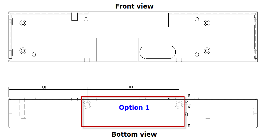
Each UMD will be shipped rack-mount ready. In addition to rack-mount option, the UMD SD 19" has two and the UMD SD ½-19" one alternative mounting options.
UMD SD 19"
.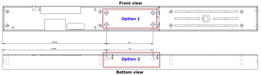
UMD SD ½-19"
Power Connector
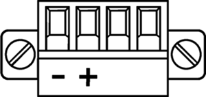
Phoenix MC 1,5/ 4-STF-3,81
Connector for DC-supply: 4-Pin connector (MC 1,5/ 4-STF-3,81) locked with two screws. The connector is already mounted on the power-supply delivered with each vsmUMD panel.
Power Supply
| Product | Description | Item Number |
|---|---|---|
Desktop-Adapter | 12V DC power supply, 4-Pin-Phoenix-Type | 799-0089-000 |
![]() (EN) Warning
(EN) Warning
It is understood that only the external Power-Supply-Unit (PSU) provided by Lawo, and shipped with the specific vsm device, is used for operating the product.
To feed the device via the DC input (exempt power core) it is mandatory to use a 12V power source that is certified as “SELV/LPS” (if certified according to 60950) or as “ES1/PS2(LPS)” (if certified according to 62368) “NEC Class 2” 12V power source. The UL mark is valid only with use of UL certified PSUs of categories QQGQ (UL 60950) or QQJQ (UL 62368). The supplied Lawo 12V PSU is compliant to these requirements.
![]() (F) Avertissement
(F) Avertissement
Il est entendu que seul le bloc d'alimentation externe fourni par Lawo, et livré avec le dispositif vsm spécifique, est utilisé pour faire fonctionner le produit.
Pour alimenter l'appareil via l'entrée DC, il est obligatoire d'utiliser une source d'alimentation 12V conforme aux exigences «SELV / LPS» (si certifiée selon la norme IEC 60950) ou «ES1 / PS2 (LPS)» (si certifiée selon la norme IEC 62368) Source d'alimentation 12V “NEC Classe 2”. La marque UL est seulement valable quand l'alimentation elle-même est certifiée par UL dans les catégories QQGQ (norme UL 60950) ou QQJQ (norme UL 62368). Le bloc d’alimentation Lawo 12V fourni avec l’équipement est conforme à ces exigences.
Serial Interface and Wiring

Connectors on rear side of UMD for serial data:
- 1 x RS422 via RJ45 connector
- 1 x RS422 (loop through) via RJ45 connector
- Serial Baud Rate will be configured automatically by the master device (vsmSmartHub) to 115200 Baud.
Notice for wiring
- NC: no connection; do not connect to any signal or supply
- Only use shielded CAT5 (or higher standard) -specified networkable. Refer to TIA-568A or TIA-568B for wiring.
- Do not use cable-traces longer than 100m (328ft) between the UMD and the vsmSmartHub
- Make sure to keep to wiring standards and use shielded RJ45-plugs for shielded cable on both ends of the line
RS422 is a differential signal transfer. Each Tx and each Rx line has both a positive and a negative pole. It is therefore absolutely necessary that twisted pair is used for Tx and Rx. UMD connections can easily be done by preconfigured standard shielded network cable (CAT5 or higher standard). To avoid potential difference between devices, shielded cable and shielded plugs with ground potential on both sides should be used. (Metalized plug-covers of RJ-45-plugs to touch ground-flange of RJ-45 connectors). Wrong wiring, wrong cables, wrong use of twisted pair and non-shielded traces lead to short working distances. Bad connection at one of the core in twisted pair traces may lead to a working unit, which seems to be working fine, but sometimes loses connection or showing strange behavior. Always use a cable-tester before installing vsmGear-products to make sure that there will be no unsuspected trouble with connected devices. Also check correct wiring of wire-shield-traces.
The RS422 (UMD-to-vsmSmartHub) connection via shielded network-cable is to be established within the same building and needs to follow the rules of approved certified IT equipment.
It is mandatory, that copper based Serial RS422-connections coming from the UMDs (CAT 5 or higher standard, RJ45) are led inside the same building to a vsmSmartHub that transfers the RS422-signal into Ethernet. The copper based Ethernet-connections (CAT 5 or higher standard, RJ45) of the vsmSmartHub are led inside the same building to the third party-device-ethernet-switch. If the Ethernet connection needs to be led outside a building it is mandatory to use an optical fiber. Use a converter to optical fiber and connect it in a short way (inside the building) to the vsmSmartHub.
![]() (EN) Warning
(EN) Warning
It is mandatory, that copper based Serial RS422-connections coming from the UMDs (CAT 5 or higher standard, RJ45) are led inside the same building to a vsmSmartHub that transfers the RS422-signal into Ethernet. The copper based Ethernet-connections (CAT 5 or higher standard, RJ45) of the vsmSmartHub are led inside the same building to the third party-device-ethernet-switch. If the Ethernet connection needs to be led outside a building it is mandatory to use an optical fiber. Use a converter to optical fiber and connect it in a short way (inside the building) to the SmartHub.
![]() (F) Avertissement
(F) Avertissement
Il est obligatoire que les connexions série RS422 à base de cuivre provenant d'UMD (norme CAT 5 ou supérieure, RJ45) doivent être acheminées dans le même bâtiment vers un vsmSmartHub, où elles sont converties en Ethernet. Les connexions Ethernet cuivre (CAT 5 ou supérieure, RJ45) du vsmSmartHub doivent ensuite être acheminées vers le switch Ethernet suivant dans même bâtiment. Si la connexion Ethernet doit être établie à l'extérieur d'un bâtiment, utilisez un convertisseur fibre optique et connectez-le au SmartHub le plus proche possible (à l'intérieur du bâtiment)
GPI (General Purpose Input) Interface
Connector for GPI: 8-Pin connector locked with two screws (MC 1,5/ 8-STF-3,81). The plug is separate and not included in UMD delivery by default.
| |||||||
| I1 | - | I2 | - | I3 | - | I4 | - |
| Input/GND [0...5 VDC] | Input/GND [0...5 VDC] | Input/GND [0...5 VDC] | Input/GND [0...5 VDC] | ||||
| In No. 1 | In No. 2 | In No. 3 | In No. 4 | ||||
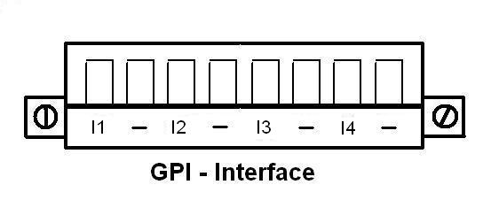
Each UMD features four GPI inputs for use as external Tally hardware inputs. The built-in GPI inputs follow PS1 (electrical power source class1).
The GPI input will not allow power to exceed 1W by the device itself.
- Open circuit voltage GPI input: approx. 3,8V DC, max. 5V DC
Short circuit current GPI input: approx. 8mA
Loaded circuit current with externally 5V (PS1) supplied: approx. 12mA
![]() (EN) Warning
(EN) Warning
It is understood that if supplying any external voltage (DC only) to the GPI input, it is never to exceed 5V DC rms and must also follow the PS1-rules (b-IEC 62368-1) to never source more than 15W.
Check polarity if external voltage is supplied. Always connect GPI input-ground to external supply-ground! Never apply any AC-voltage to the GPI inputs!
![]() (F) Avertissement
(F) Avertissement
Il est entendu que si une tension externe (DC uniquement) est fournie à l'entrée GPI, elle ne doit jamais dépasser 5V DC rms (valeur efficace) et doit également suivre les règles PS1 (norme b-IEC 62368-1) pour ne jamais fournir plus de 15W.
Vérifiez la polarité si une tension externe est fournie. Toujours connecter la masse de l'entrée GPI à la masse de l'alimentation externe! Ne jamais appliquer de tension AC aux entrées GPI!
(EN) Information
This Interface is a small signal interface only, and uses same ground potential.
The GPI DC TTL Inputs are able to "set" a readable input by either shorting the input to ground , or by supplying any 5V DC-voltage and undershooting 2,3V DC respective to ground.
(F) Information
Cette interface n'est qu'une interface basse tension, faible courant.
Les entrées GPI DC TTL sont capables de "régler" une entrée lisible soit en court-circuitant l'entrée à la terre, soit en fournissant une tension de 5 VDC et une sous-tension de 2,3 VDC respectivement à la terre.
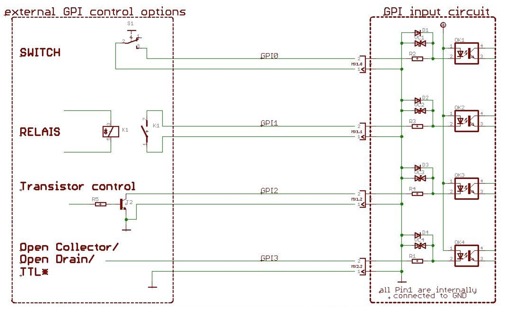
Possible GPI Input wiring and control options
Getting Ready for Operation
First configure a vsmSmartHub port as UMD-Proxy as described in the vsmSmartHub User Manual and setup the bus address on the rear side of the UMD.
If there is more than one UMD in the chain, consider following daisy chain rules for the RS422 bus:

- Do not use cable-traces longer than 100m (328ft) for one complete RS422 chain.
- Do not Y-connect the RS422-traces.
- Loop UMDs through UMDs in an RS422 chain using standard 1:1 network cable.
- Use separate PSUs for each UMD to minimize single point of failure.
- Only use enclosed PSUs or alike for UMDs for proper operation.
- It's not recommended to chain more than 32 UMDs in one RS422-trace.