.edge - Multicast IP Addresses
This topic describes how to define the multicast addresses for the IP senders.
Overview
In order to publish streams to the network, each IP sender must be assigned a unique multicast IP address. As there are many streams to configure, the system provides three ways to allocate the addresses:
- Source IP Based (fully automatic).
- Custom Ranges (semi-automatic). The user must define an IP Start value (for each type of flow).
- Manual (no automation). The user must define the multicast addresses manually (for each IP sender).
The first method is the simplest as it offers complete automation. The second and third methods can be used if you need more manual control (e.g. to fit an existing multicast scheme).
The rest of this topic describes the formulas used for options 1 and 2, and the configuration steps for all three methods.
Source IP Based (Formula)
In this mode, the multicast addresses are generated automatically based on the IP addresses of the media network ports (the source IPs). The table below shows the formula used.
As an example: if the Source IP is 172.18.100.24, then the Multicast IP Addresses will be 239.100.24.xxx
The xxx (4th octet) values are generated automatically for each type of flow: Video, Audio and Meta, plus the Audio Router and Video Proxies if these options are enabled.
In each case, the IP ranges are generated automatically so that there are no overlaps in the multicast IPs. Using this method ensures that every multicast address is unique for all of the possible IP senders.
| 1st Octet | 2nd Octet | 3rd Octet | 4th Octet | |
|---|---|---|---|---|
| Media Port Source IP | aaa | bbb | ccc | ddd |
| Multicast IP Address | 239 | ccc | ddd | xxx |
| Always 239 (this is fixed) | Matches 3rd octet of the source IP | Matches the 4th octet of the source IP | Generated automatically (as described below). |
The sections below describe the IP ranges for each type of flow.
Video, Audio and Meta (Ranges)
The table below describes the IP ranges for the Video, Audio and Meta streams. Note that the maximum number of SDI inputs (per blade) is 32.
| Video | Audio | Meta |
|---|---|---|
There is 1x video flow for each SDI input. | There are 4x audio flows for each SDI input. | There is 1x meta flow for each SDI input. |
Video flows use the range 1-32 SDI input 1 Video: x = 1 | Audio flows use the range 33-160 SDI input 1 Audio: x = 33 .. 36 | Meta flows use the range 161-192 SDI input 1 Meta: x = 161 |
Audio Router (Range)
If the Audio Router is enabled, then there are up to 64 Audio Router senders (per blade).
Audio Router flows use the range x.193 to x+1.0
Audio Router Tx 1 = x.193
- Audio Router Tx 2 = x.194
- Audio Router Tx 3 = x.195
- ..
- Audio Router Tx 63 = x.255
- For the 64th sender, the 4th octet reaches overflow and so the next IP increments the higher level octet(s).
For example: if Tx 1 = xxx.xxx.6.193, then Tx 64 = xxx.xxx.7.0
Video Proxies (Range)
If the processing blade supports video proxies, then the full resolution video streams are transmitted from the 100G ports, while the proxies are transmitted from the 25G ports.
This means that the Source IPs (of the media ports) are different and so the same Source IP Based formula can be used.
For the xxx (4th octet) value, the video proxies use the range 1-96.
There are 3x proxy flows for each SDI input (at 1:4, 1:16 and 1:64 resolution).
- SDI input 1 Video proxy: x = 1 .. 3 (.1=1:4, .2=1:16, .3=1:64)
- SDI input 2 Video proxy: x = 4 .. 6
- SDI input 3 Video proxy: x = 7 .. 9
- ..
- SDI input 32 Video proxy: x = 94 .. 96
Custom Ranges (Formula)
In this mode, the user must define an IP Start value for each type of flow: Video, Audio, Meta, etc. The multicast addresses are then generated automatically by counting upwards from the start value.
If the 4th octet reaches overflow (above 255), then the next IP increments the higher level octet(s).
In table form, the formula looks as follows:
| 1st Octet | 2nd Octet | 3rd Octet | 4th Octet | |
|---|---|---|---|---|
| Multicast IP Address | aaa | bbb | ccc | xxx |
| custom-defined | custom-defined | custom-defined | Generated automatically by counting upwards from the IP Start value. |
When preparing a custom multicast scheme, please bear in mind the following points:
- An IP Start value is required for both the primary and secondary networks.
- When using this mode, the user must ensure that there are no overlaps between the IP Ranges (to keep each multicast IP unique).
- The system offers some default IP Start values to help you. However, these are identical for every blade, and so you will usually need to edit the fields (to fit your multicast scheme).
Configuration via HOME
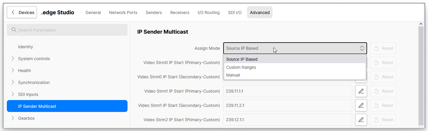
The method used for the multicast IP address assignments is defined using the Assign Mode parameter (in the IP Sender Multicast page of the blade's Advanced parameters).
- From HOME's 'Devices' list, click on the processing blade label to open the 'General' settings page (as described earlier).
- From the menu tabs, select Advanced and then, from the parameter tree (on the left) select IP Sender Multicast.
The Assign Mode field defines the method of assignment for the multicast IPs: Source IP Based, Custom Ranges or Manual.
Please note: If you change the Assign Mode to either Source IP Based or Custom Ranges, then the "new" multicast addresses are pushed immediately to the network(s).
Below the Assign Mode are the IP Start and IP Range fields for the processing blade. In each case, there are two fields (for each flow type) to deal with the primary and secondary network senders.
Before using this page, it is useful to know that:
- The IP Range fields show the current multicast addresses (when using Source IP Based or Custom Ranges).
- The IP Start values are only relevant when using Custom Ranges.
- If you change the multicast address of an individual sender (e.g. from the Senders tab or Advanced parameters), then this action will set the Assign Mode to Manual.
- When the Assign Mode is set to Manual, the IP Range and IP Start fields are ignored (as each multicast address must be set independently).
The number of visible fields is dependent on the blade's operating mode and options as follows.
- There are 2x Video, 2x Audio and 2x Meta fields for each blade with SDI to IP gateway functionality.
- If the Audio Router is enabled, then there are 2x Audio Router fields.
- If the blade's operating mode supports video proxies, then there are six additional Video fields. In this instance:
- The Video Strm0 fields are for the original 1:1 video flows (transmitted from the 100G ports).
- The Video Strm1 and Video Strm2 fields are for the 1:4, 1:16 and 1:64 video proxy flows (transmitted from the 25G ports).
To setup the multicast addresses, please follow the instructions below (for your preferred Assign Mode method).
Option 1: Source IP Based (Assign Mode)
If the Assign Mode is set to Source IP Based, then the IP Ranges are generated automatically from the media port source IPs (as described earlier).
This is the simplest method of assignment as it offers complete automation. Using this method ensures that every multicast IP is unique (assuming there are no source IP conflicts).
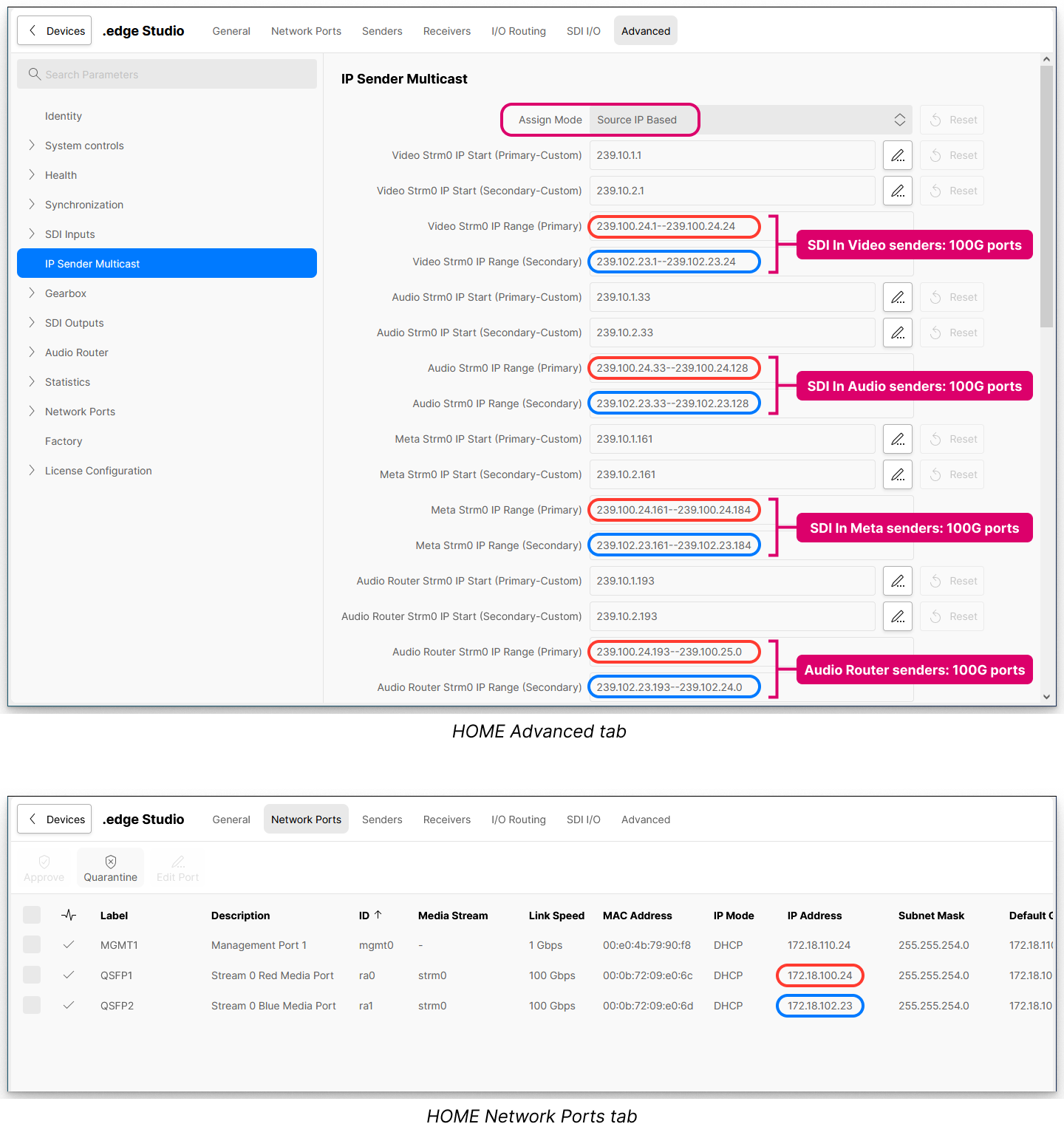
Once the Source IP Based mode is selected, the IP Range addresses are pushed to the network(s) immediately, and no further action is required. If you need to check the source IPs, then this can be done from the Network Ports tab.
In the examples below, the IP addresses for primary network are outlined in red and those for the secondary network are outlined in blue.
In this example, the blade's FPGA mode supports 100G Gateway SPS operation and so the Source IPs for the multicast addresses comes from the 100G ports. There are no proxy flows and so you see the IP Ranges for the SDI Input Video, Audio and Meta senders plus the Audio Router senders (if this option is enabled).
Option 2: Custom Ranges (Assign Mode)
If you wish to create your own custom IP ranges, then this is possible by editing the IP Start values and then switching the Assign Mode to Custom Ranges.
The IP Ranges are generated from the IP Start values by counting upwards (as described earlier). You can use either the default IP Start values or edit the fields (to fit your chosen multicast scheme).
1. Start by checking (and editing) the IP Start values for each stream essence.
The example below shows how to edit the Audio Strm0 IP Start value.
- Click on the pencil icon (to open the edit dialog).
- Enter the IP address.
- Click on Confirm (to apply the change).
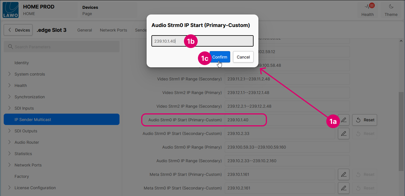
- Repeat these steps for each IP Start field.
- You can use the Reset buttons to reset to the default values.
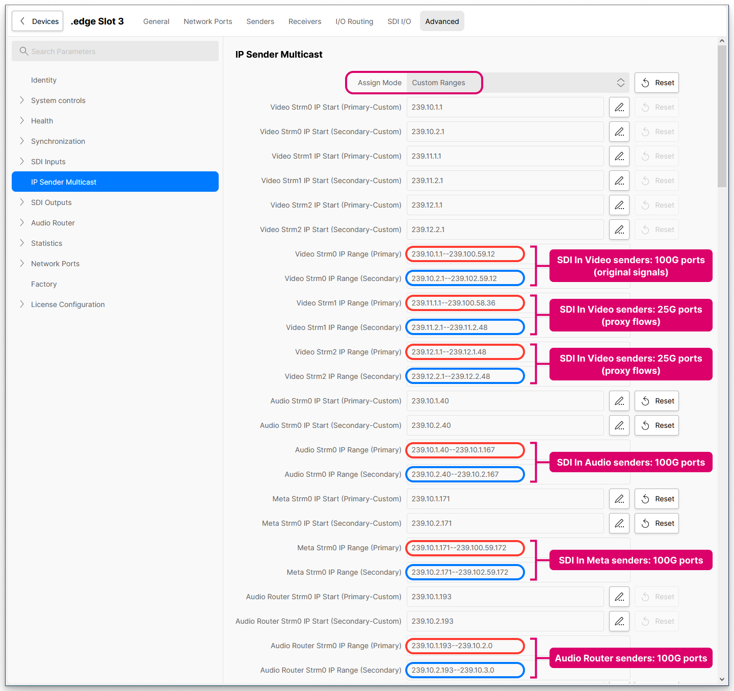
2. Once you are happy with the IP Start values, change the Assign Mode to Custom Ranges.
The IP Range fields update, and the addresses are pushed to the primary (red) and secondary (blue) networks.
In this example, the blade's FPGA mode supports 100G Gateway SPS + 25G Proxy SPS operation, and so you see the additional IP Ranges for the SDI Input Video Proxy flows.
3. If you need to edit an IP Range, then re-open the IP Start edit dialog and enter the new value.
Click on Confirm (to apply the change). The corresponding IP Range field updates, immediately, and the new addresses are pushed to the network.
Option 3: Manual (Assign Mode)
The Manual mode can be used if you wish to define the multicast IP addresses manually. In this mode, the IP Ranges in the IP Sender Multicast page are ignored (so that you can define the multicast address for each individual IP Sender).
Important: The user must ensure that each multicast IP is unique (to avoid any conflicts).
Please bear in mind that using this mode can be a lot of work, as you will need to check (and edit) the multicast address for each individual IP sender.
- Start by opening the IP Sender Multicast page and set the Assign Mode to Manual.
If you skip this step, then the system will automatically set the Assign Mode to Manual once the multicast address of an individual IP sender is changed. - Then open the SDI Inputs branch (of the Advanced parameters).
- Open SDI#01, IP Senders and Video.
- Click on the pencil icon(s) to edit the IP Primary Multicast and IP Secondary Multicast field(s). In each case, type in the required address and click on Confirm (to apply the change).
- Repeat for each essence: e.g. 1x Video, 3x Video proxies, 4x Audio and 1x Meta
- Then repeat for the next SDI input (up to 32 depending on the SDI Configuration).
- Then repeat the process for any additional IP senders (e.g. from the Audio Router).
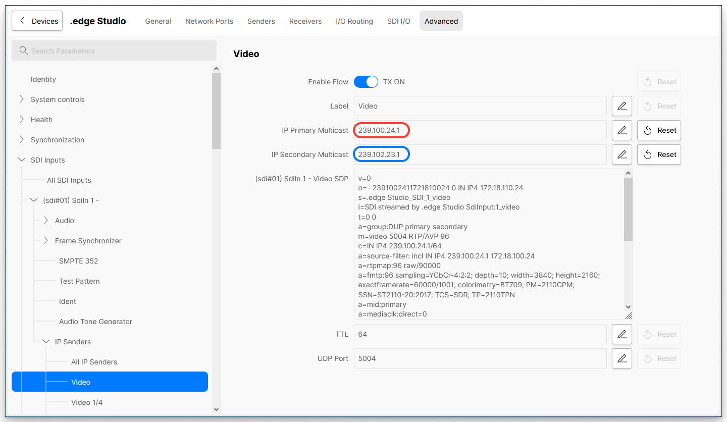
SDI Inputs → SDI#01 → IP Senders → Video
UDP Port, RTP and TTL Values
If you scroll further down the IP Sender Multicast page, then there are some additional fields. These can be used to change the UDP Port, RTP payload or TTL (TimeToLive), globally, for all IP senders.
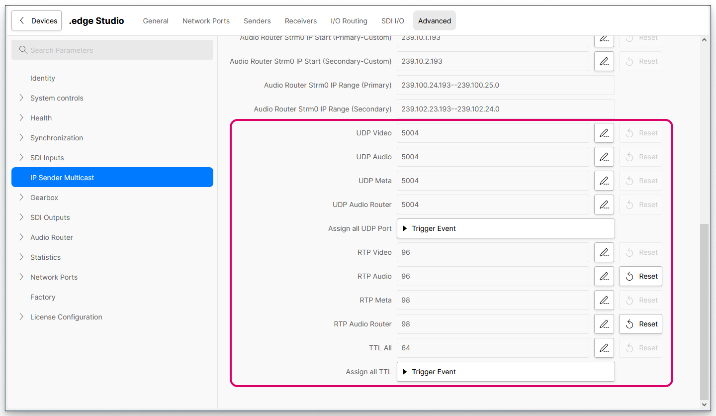
Advanced → IP Sender Multicast
- Start by entering the required values into each field. You can use the Reset button to enter the default value.
- Then select the Trigger Event button(s) to push the values to the IP senders. There are two Trigger Event buttons so that you can update the UDP Port numbers and RTP/TTL values separately.
Important: Any changes applied to an individual sender will be overwritten once you select Trigger Event.
Please note:
- The UDP Port numbers can be different for Video, Audio, Meta and Audio Router streams. The default value is 5004 (for all essence types).
- The RTP payload values can be different for Video, Audio, Meta and Audio Router streams. The default values are RTP Video (96), RTP Audio (97), RTP Meta (98) and RTP Audio Router (97).
- There is one TTL value for all streams. The default value is 64.
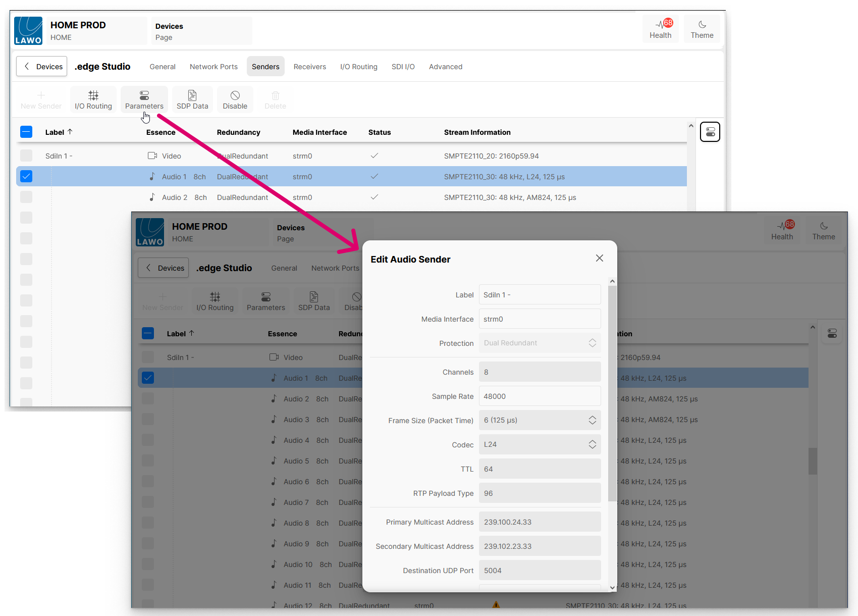
Check the IP Senders
All of the settings above can be checked (and edited) for each IP sender from the Senders tab as follows.
- From the main "Devices" list, click on the processing blade label (to open the "Device Details" as described earlier).
- Then select the Senders tab to view all of the IP senders.
- Select a sender (e.g. SdiIn1 Audio 1).
- Click on Parameters to open the "Edit Sender" dialog.
- From here you can check and edit all of the individual sender parameters, including the Primary and Secondary Multicast Address plus the Destination UDP Port, TTL and RTP Payload Type.
Please note: It is not possible to apply different RTP payload values to senders of the same type.
This means that, if the RTP Payload Type is changed for an individual sender, the new RTP value is applied to all senders of the same type. e.g. to all Audio Senders.