.edge - Operating Principles
Before configuring .edge, it is useful to understand how each processing blade is controlled and where its settings are stored.
Configuration and Control
All of the parameters for a processing blade are controlled, via the network, in one of three ways: using HOME, Ember+ or REST API.
As .edge supports native control via Lawo's HOME, this topic assumes that you using HOME as the control interface. Note that the same parameters can be accessed (via Ember+ or REST API). This supports integration with external control systems such as Lawo's VSM.
Prerequisites
It is expected that customers will have a HOME system (for device management) and so, once the HOME server(s) are configured, .edge devices are automatically detected by HOME.
You can learn how to configure the processing blade's network interfaces later.
For now, it is useful to know that, by default, the MGMT 1 port is configured for DHCP. This means that, once a blade is connected to the HOME network using MGMT 1, its control IP address is assigned automatically (by HOME's DHCP server).
Opening a Connection to HOME
The computer must be connected to the same network and subnet as the HOME management system server(s).
The HOME UI is accessed by entering the IP address, or domain name, of the HOME server into a web browser and then signing in.
- Open your web browser application and type in either
http://HOME-IP-address:5000/or the domain name of the HOME server followed by port:5000. Press Enter. - At the "Sign in" screen, enter the following credentials: Username = lawo; Password = lawo.
- Following a successful sign in, the HOME 'Devices' page appears.
For more information and troubleshooting, please see Opening a Connection to HOME (in the HOME User Manual).
HOME UI Operation
The image below explains the basic operation of the 'Devices' page (when viewed on a reduced-width screen).
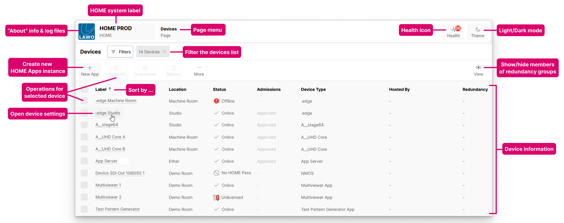
The HOME user interface can operate in either light or dark mode. Click on the Theme icon (top right) to toggle between the modes.
The Filters button can be used to filter the contents of the list. For example, to view only the devices in a particular location.
For more information about these, and other features of HOME, please see HOME - User Interface Operation.
Identifying the .edge Devices
In HOME's 'Devices' list, each .edge processing blade appears as a separate device. So, if you connect all four processing blades (from a single frame), then HOME displays these as four separate entries.
By default, the blades are assigned a default label: .edge_Slot1 to .edge_Slot 4, where slot 1 is the master processing blade (fitted to the highest physical slot in the frame).
- If a processing blade does not appear, or its Status shows as Offline, then check that it is powered and connected to the HOME network.
- If the status of a processing blade is showing as Quarantined, then it must be approved before you can continue. To learn more, please see Approve or Quarantine a Device (in the HOME User Manual).
- If you need help identifying each processing blade, then you can use the Identify Hardware function.
- The label and location of each processing blade can be edited using the Edit Device Info function.
For more information about the fields in the 'Devices' list, please see HOME - Devices (in the HOME User Manual).
Reconfiguring a Blade
All of the settings for a processing blade can be accessed, from HOME's 'Devices' list, by clicking on the device label (1) and choosing a menu tab (2).
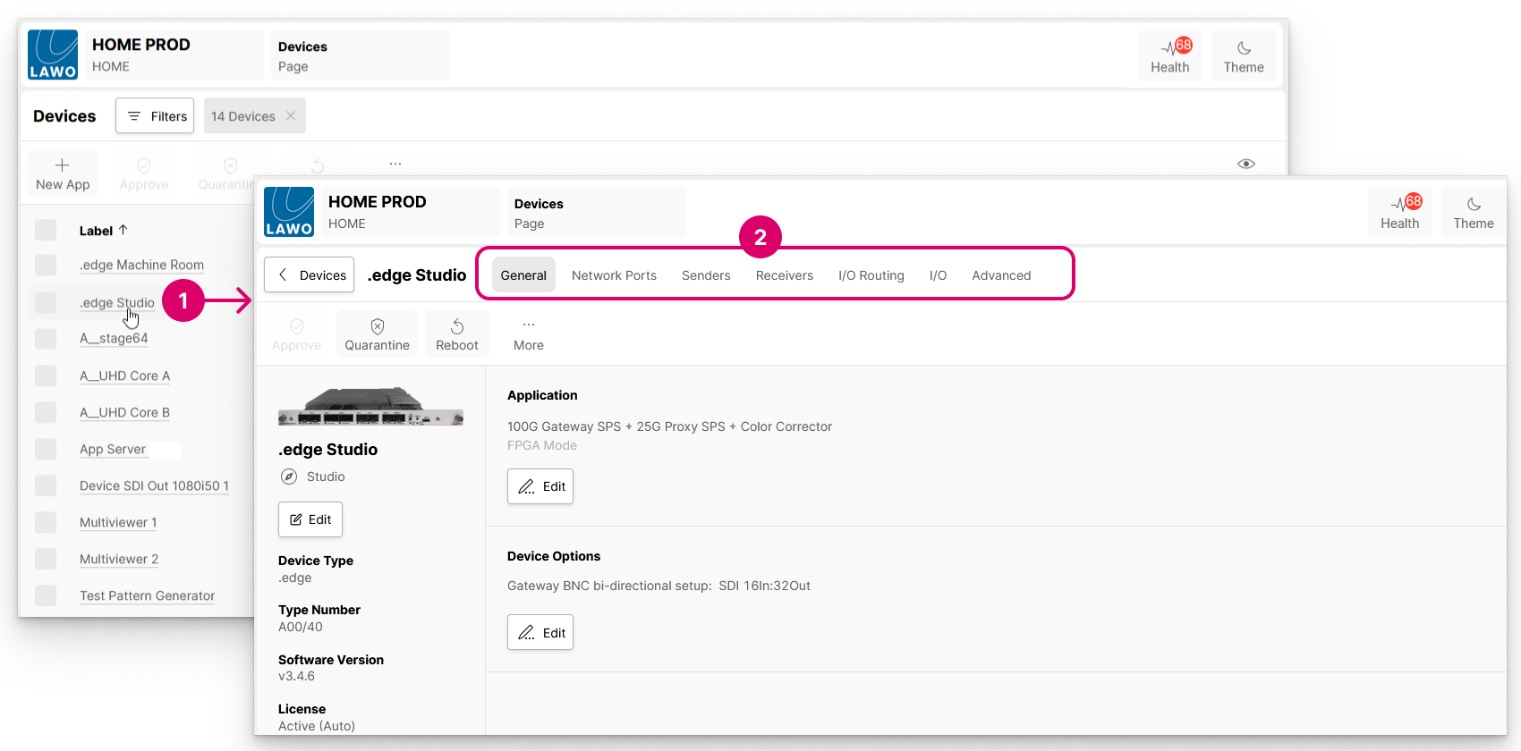
The menu tabs provide access to a variety of device-specific parameters such as the label and location, configuration options, IP settings, senders and receivers, and so on.
If a blade is Offline or has No HOME Pass, then a page with minimal content opens.
In this instance, check that the device is powered and connected to the network, and that it has a valid HOME Pass (license). For more information about the licensing, please see HOME - HOME Passes.
To return to the main 'Devices' list, click on the < Devices button (to the left of the device label). From here, you can repeat the steps above to access another device or app.
Where are the settings saved?
The latest settings are stored automatically on the processing blade whenever a change is made.
Device Settings (overview)
For each .edge processing blade, there are seven pages of settings. The first five (General, Network Ports, Senders, Receivers and I/O Routing) are available for most streaming devices. The last two (I/O and Advanced) are specific to .edge.
Click to expand the descriptions below for an introduction to each page.
The General settings is the first landing page that appears whenever you click through to an individual device. It includes information about the processing blade (on the left) and other settings (on the right).
The informational fields (on the left) include the current label and location, Software Version and Serial Number (important for licensing). The Edit button can be used to edit the device label and location. The Identify Hardware function can be used to identify the blade by flashing its Call HOME LED on the front panel.
The settings (on the right) show the Application (FPGA mode) and Device Options (SDI I/O configuration). The Edit buttons can be used to modify the settings (as described in .edge - Operating Mode and .edge - SDI Configuration).
The Network Ports page lists all of the processing blade's active network ports. From here you can check the status of a port or edit its network settings.
The Senders and Receivers pages list the processing blade's senders and receivers. These are pre-defined according to the SDI I/O configuration and Audio Router option. For example:
- If the SDI configuration = 24 In:24 Out, then there are 24 SDI senders + 24 SDI receivers, where each one handles multiple flows (that correspond to the SDI input or output): 1x Video, 4x Audio and 1x Meta(data).
- If the Audio Router option is enabled, then there are an additional 64 AudioTx senders and 128 AudioRx receivers. In this instance, each one handles a single Audio flow.
If you select a sender or receiver, then it is possible to adjust the I/O Routing (for the audio streams), edit the streaming parameters or access the SDP data. In addition, the "Show Sidebar" button (on the right) reveals the available properties for the selected sender or receiver. For example, for an audio sender, you can adjust the delay or turn on the test tone.
The I/O Routing page can be used to map the audio channels of IP receivers to the audio channels of the IP senders for the Audio Router.
Please note:
- If the Audio Router option is not enabled, then there are no signals to configure.
- If you wish to shuffle the audio channels of an SDI sender or receiver, then this is done from the Senders or Receivers tab (as described here).
The I/O page can be switched between SDI Inputs and SDI Outputs. It provides a quick overview of the connections including signal present (for Video and Audio), and which options are enabled (Frame Sync, Ident, Test Pattern, Gearboxing).
The "Show Sidebar" button (on the right) reveals the available properties for the selected input or output. For example, for an SDI input, you can turn on the ident and test pattern, or adjust the gearboxing and input frame sync (if the relevant licenses are active).
The Advanced page provides access to ALL of the available parameters for a processing blade. It is designed for technical users who need access to more advanced settings and informational fields.
Signal Streaming
Once a processing blade is part of the operational network, its streaming connections can be managed from HOME's 'Stream Routing' page.
The image below explains the basic operation of the page:
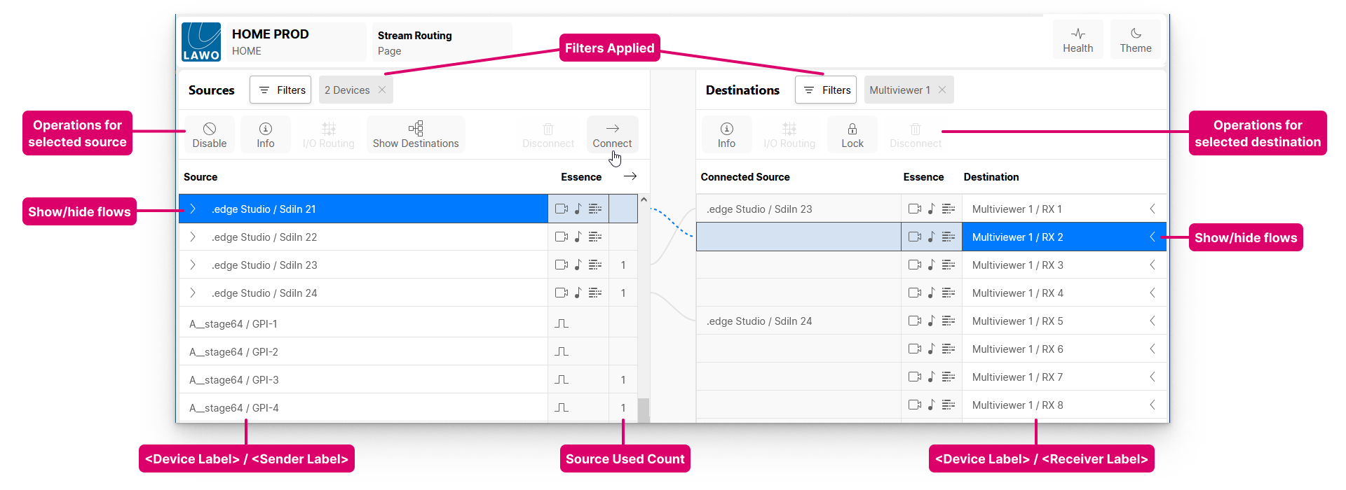
The IP senders and receivers are either pre-defined (according to the device configuration) or created manually. You can check the current configuration from the Device → Senders or Device → Receivers page (as described here). As part of the configuration, users can choose the stream transport, video resolution, number of audio channels, etc. This allows the IP senders and receivers to be tailored to the application and network (to help manage the bandwidth of the switches and NICs).
Once a connection is made, signals are streamed via the device's media Network Interface Cards (NICs). Or, in the case of HOME Apps, the NICs of the target app server. To achieve redundant streaming, compatible with SMPTE ST2022-7, the NICs must be configured in pairs to support the primary and secondary streams.
If a device supports audio streams, then the 'I/O Routing' (for the senders and receivers) maps the audio channels carried by the streams to the device's local audio inputs and outputs.
For more information, please see .edge - Stream Routing.