.edge - Audio Handling
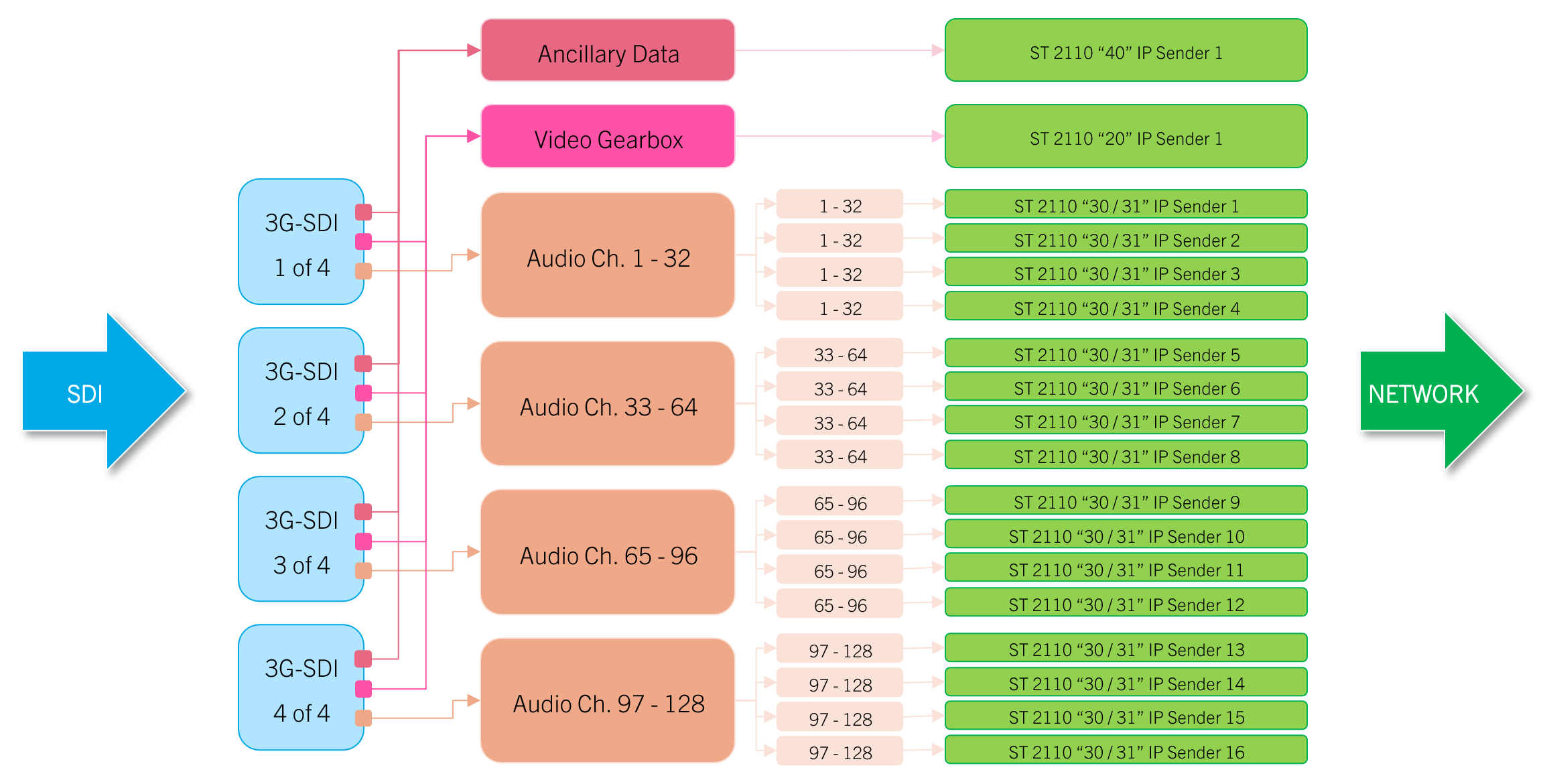
This topic describes what happens to the different essences during the SDI to IP conversion process. In particular, it is important to understand how the audio channels are handled, as .edge supports audio shuffling and test-tone insertion (on both the input and output sides). These parameters can be adjusted whenever you configure an IP sender or SDI output.
Overview
Options for IP Senders
- Audio (de-embedding) – independent mono audio channel mapping per IP sender, selectable number of channels (up to 16 or 32 depending on the SDI signal type)
- Test tone generator insertion – 400Hz to 1kHz frequency control with decreasing ramp (0.5dB per channel)
Options for SDI Outputs
- Audio (embedding) – independent mono audio channel mapping per SDI output, selectable number of channels (up to 64)
- Test tone generator insertion – 400Hz to 1kHz frequency control with decreasing ramp (0.5dB per channel)
Examples
The examples that follow describe how this works for different SDI signal types.
SD and HD (SDI)
For SD and HD signals sent to an SDI input, .edge accepts the usual 16 audio channels. These can be routed to four IP senders, in any combination.

SDI to IP Conversion (for SD/HD-SDI)
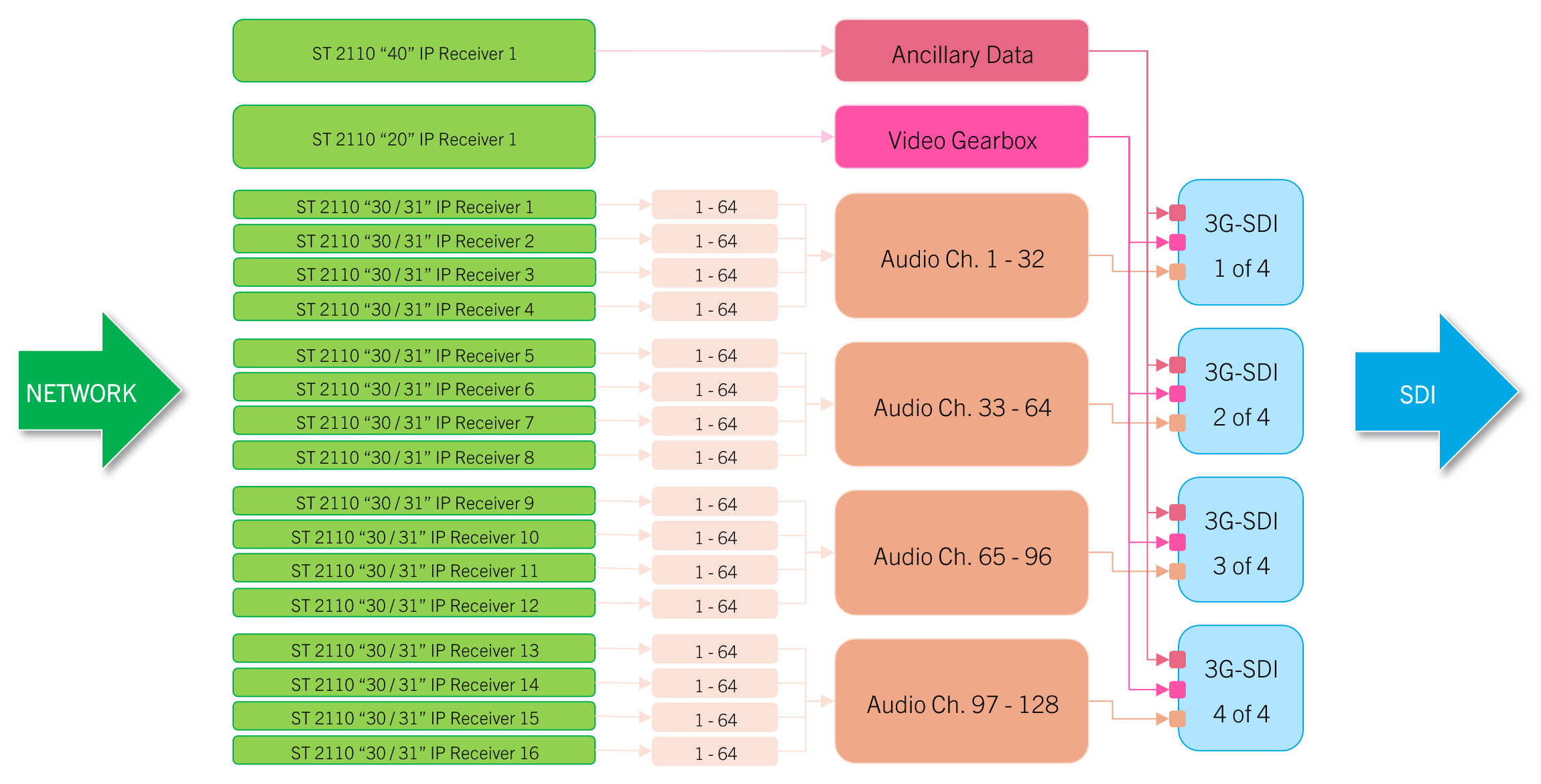
When receiving audio from the network, each IP receiver accepts up to 64 audio channels. These can include other audio signals available on the IP network as well as the ones received by the SDI input.
For the final audio packaging, any of the 64 channels sent to the four IP receivers can be shuffled into the final 16 audio channels sent to the SDI output.
Thus, it is possible to replace some or all of the original audio channels with those from a different source (e.g. audio mixing console).

IP to SDI Conversion (for SD/HD-SDI)
3G 1080p (3G-SDI)
For 3G input scenarios (at 1080p), the conversion works similarly, except that each IP sender accepts up to 32 audio channels.

SDI to IP Conversion (for 3G-SDI)
On the receiving side, each IP receiver can handle 64 audio channels (as before).
For the final audio packaging, any of the 64 channels sent to the four IP receivers can be shuffled into the final 32 audio channels sent to the SDI output.

IP to SDI Conversion (for 3G-SDI)
UHD 2160p (4 x 3G-SDI)
In quad-link 3G-SDI configurations (2160p, UHD), 128 audio channels (4 x 32 ch.) are supported and can be assigned to four IP senders per leg.

SDI to IP Conversion (for 4 x 3G-SDI)
On the output side, 4 x 4 audio receivers each support 64 audio channels and can output 32 of them. Thus, .edge supports a combined 128 audio channels (4 x 32 ch.), as defined for the 12G/Quad-Link standard.

IP to SDI Conversion (for 4 x 3G-SDI)
UHD 2160p (1 x 12G-SDI)
Single-link 12G-SDI works in the same way as quad-link 3G-SDI, the only exception being that there is no need to gearbox the video.
Configuration via HOME
To configure the audio de-embedding (and embedding) you will need to open the I/O Routing page for either the senders (or receivers). This is done as follows.
- From the main "Devices" list, click on the processing blade label (to open the "Device Details" as described earlier).
- Select the Senders tab (to configure the de-embedding) or the Receivers tab (to configure the embedding).
- Select the audio sender (or receiver) you wish to adjust and select the I/O Routing button.
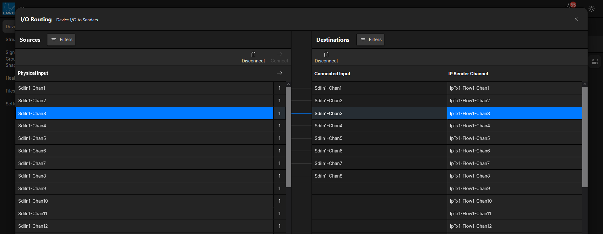
The I/O Routing page is used to connect the IP channels of the senders and receivers to the audio channels of the SDI inputs and outputs. The operation is very similar to the "Signal List" display on Lawo's mc2 consoles.
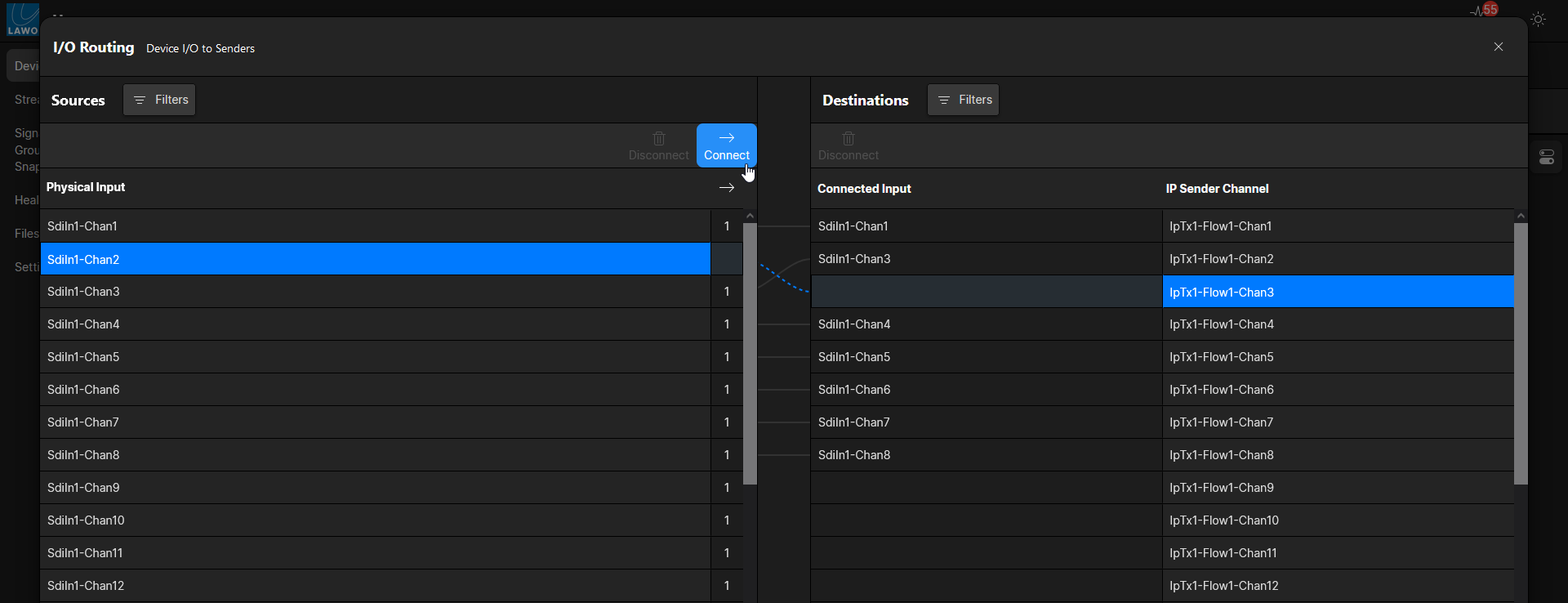
To make a connection, select a source (on the left) and a destination (on the right); then click Connect. The screenshots below show an example.
1. Start by opening the I/O Routing for an audio sender.

The default I/O routing is 1:1.

2. Select a source (on the left) and a destination (on the right) - the prepared connection is shown as a dotted line.
3. Click Connect to confirm.
In the example below, channels 2 and 3 are swapped.
