diamond - Communication Modes
As part of the system setup, a communication mode must be assigned to each control surface module.
There are three possible options: CAN+IP, CAN or IP.
- CAN+IP - allows a module to communicate with other modules via CAN, and Power Core via IP. This is the default setting for the frame's IP module (that sits above the Ethernet connector board).
- CAN - supports CAN only and not IP. Choose this mode for all modules that connect to an IP module via CAN, either internally or externally.
- IP - supports IP only and not CAN. This option can be used if the frame includes a single module and that module communicates with Power Core via IP.
Either CAN+IP, or IP, must be selected for the frame's IP connector board (to handle the IP connection to Power Core). All other modules must be set to CAN.
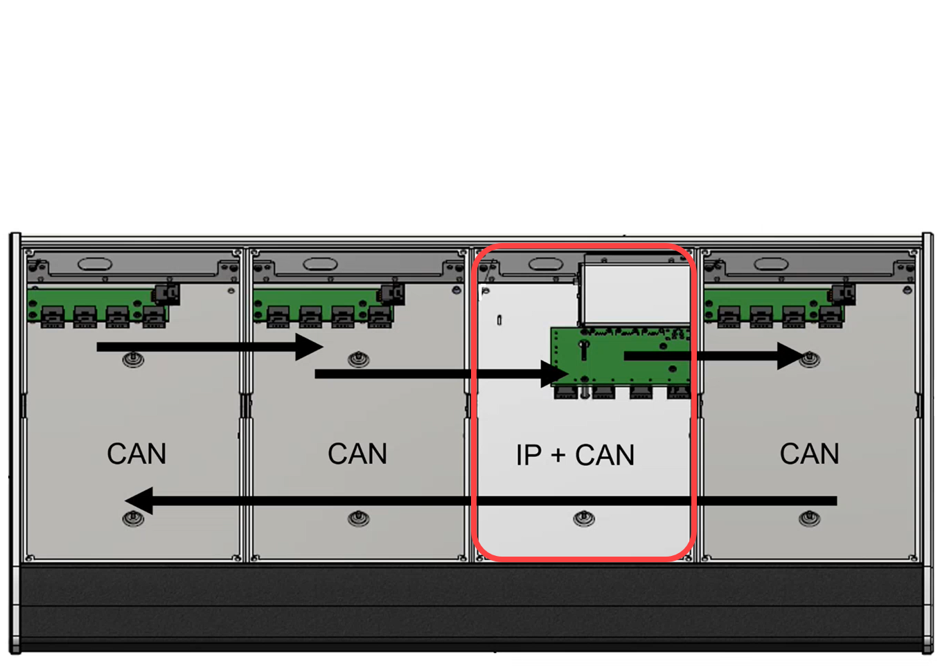
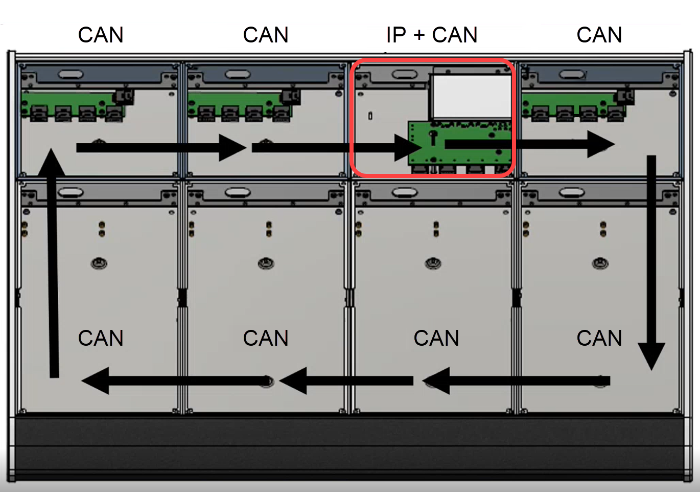
The images below show the internal wiring and communication modes for two examples: a standard frame (on the left) and extended frame (on the right). The position of the frame's IP module/connector board is highlighted in red.
|
|
The communication modes are shown on the surface displays during boot-up. In the example below, the frame's IP module is the upper Fader Extension module (assigned to slot 39).

How to Reset the Communication Mode(s)
A module can be reset to either IP or CAN using the following key combinations (while the module is booting).
Reset to IP
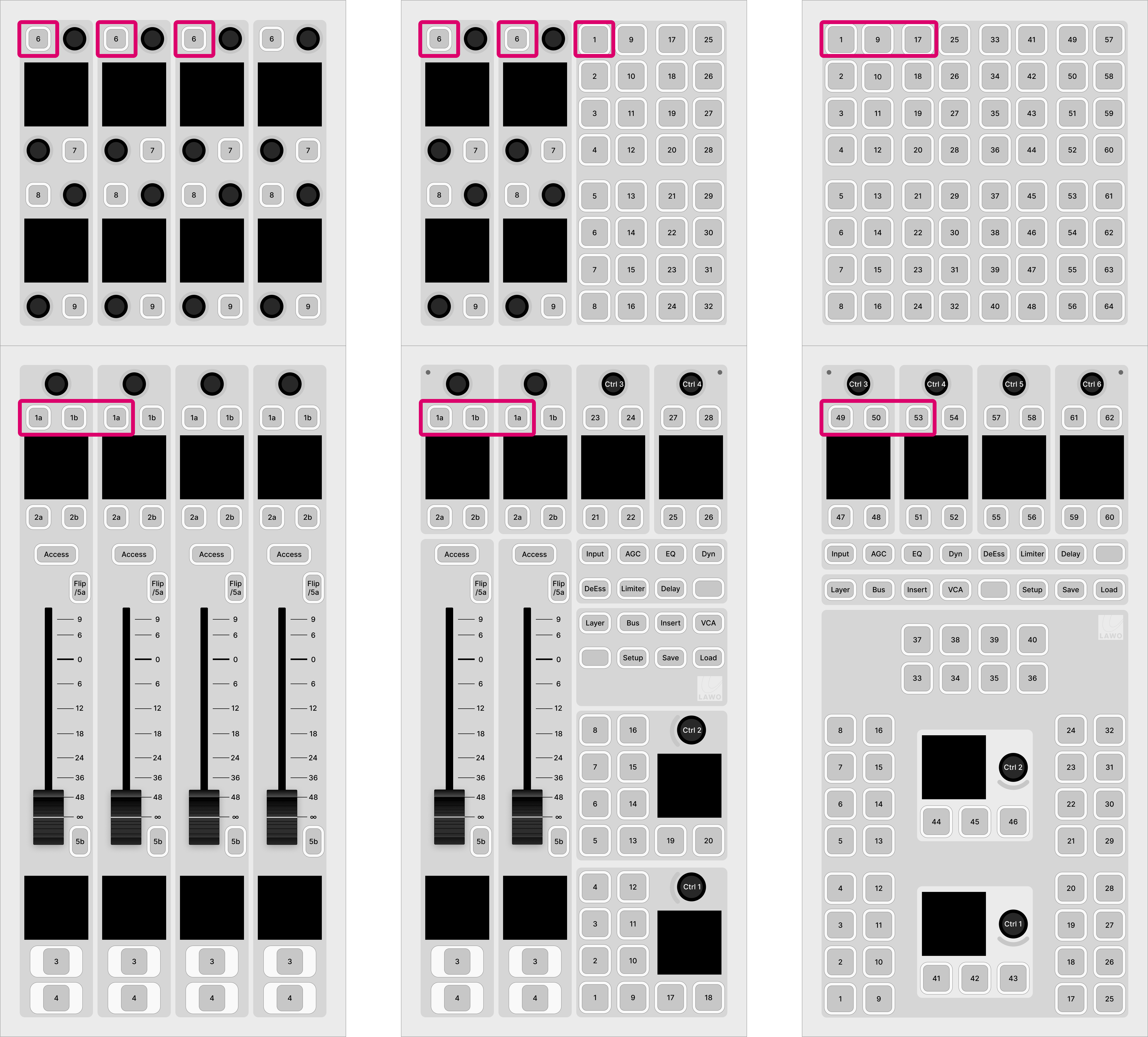
To reset a module's communication mode to "IP" and IP address to the default (192.168.101.241), press and hold the 3 upper left keys (during boot-up). The images below show the correct key combinations.
Reset to CAN
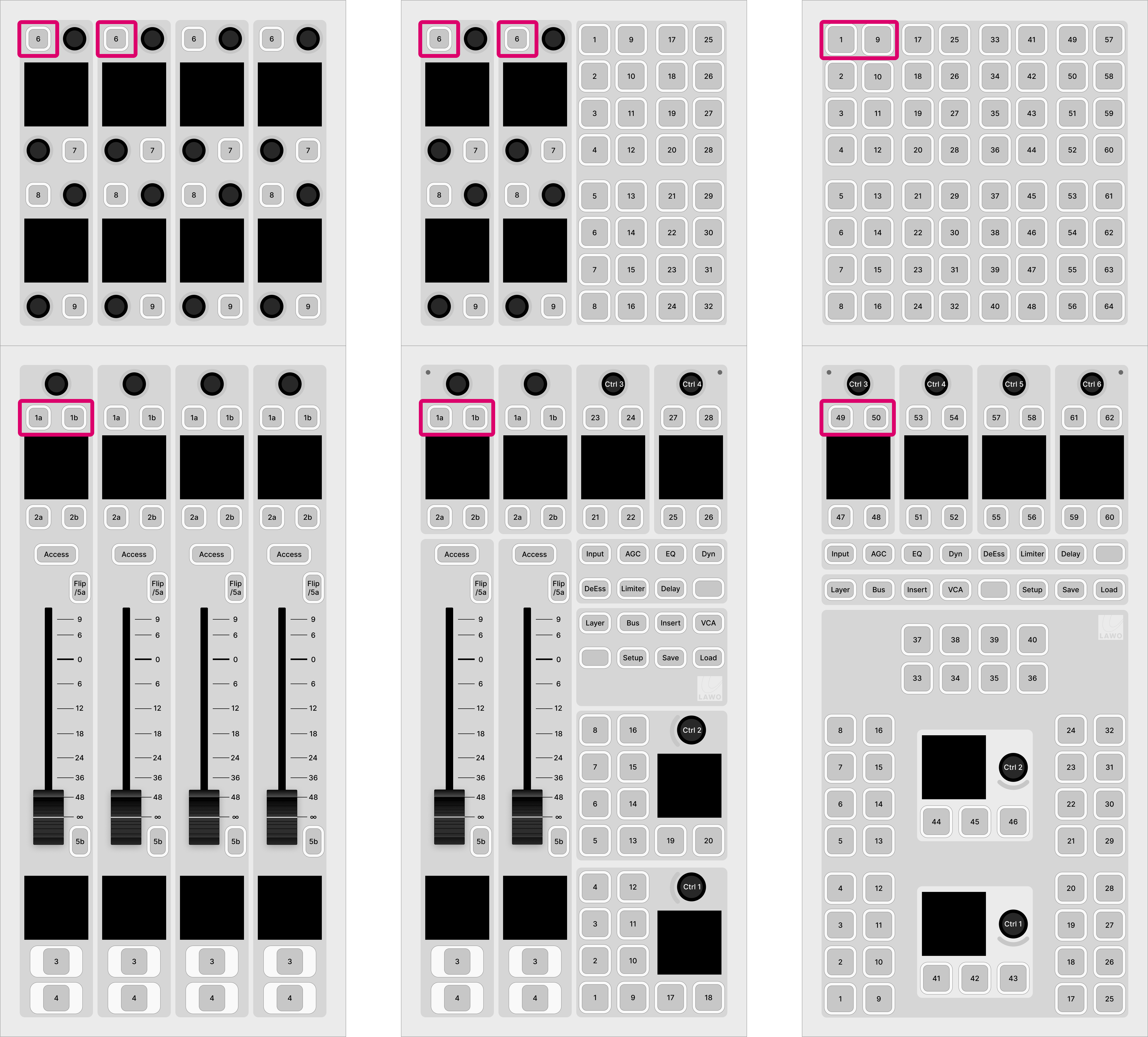
To reset a module's communication mode to "CAN" and slot ID to "0", press and hold the 2 upper left keys (during boot-up). The images below show the correct key combinations.
Reset to CAN+IP
The mode CAN+IP can be assigned to an IP module by opening a Web UI connection and changing the Mode parameter in the "Control Interface" settings.
Practical Examples
In practice these operations can be used as follows.
To set up the frame's IP module:
- Press and hold the 3 upper left keys (during boot-up) - the communication mode is set to "IP".
- Connect your configuration PC directly to the IP module (using the ETHERNET port on the underside of the frame).
- Open a Web UI connection using the default IP address of 192.168.101.241.
- Log in as either Supervisor or Administrator. The default passwords are orion for Supervisor and hydra for Administrator.
- Select the "System Control" tab and enter the correct Mode parameter in the "Control Interface" settings.: either CAN+IP or IP (if the frame has only one module).
- Reboot the IP module/frame (using the Reboot System button in the "System Control" tab).
- Select the "Network" tab and enter the required network settings. See diamond - Network Settings.
- You can now connect the diamond frame to the network.
To set up a CAN-bus module:
- Press and hold the 2 upper left keys (during boot-up) - the communication mode is set to "CAN".
- Open a Web UI connection to the diamond frame (using the network settings assigned to the IP module).
Log in as either Supervisor or Administrator. The default passwords are orion for Supervisor and hydra for Administrator.
- Select the "Surface Modules" tab and enter the correct slot ID for the module. See diamond - Slot IDs.
- In this instance, the module is ready for operation as soon as the correct slot ID is assigned. A reboot is not required.