diamond - Configuring the IP Connection to Power Core
This topic describes how the IP communication with Power Core is achieved.
If the surface consists of a single diamond frame, then this must connect to Power Core via IP. The Ethernet connection can be made directly (point-to-point) or via a network (LAN or WAN).
If the surface consists of more than one frame, then the network communication with Power Core can be achieved in one of two ways:
- The first diamond frame connects to Power Core via IP, and the second frame is daisy-chained to the first using an external CAN bus cable (CAN A).
- Each diamond frame connects individually to Power Core via IP.
If you have a diamond frame that is wider than 4 modules, then it behaves like two separate frames (with two ETHERNET / CAN connector boards).
The rest of this topic explains how to connect and configure each scenario.
The IP connection(s) to Power Core may use either a Multicast or Unicast IP address scheme. If you wish to use Unicast IPs for more than one frame, then this requires some additional configuration (in the ON-AIR Designer).
Configuring a Single Frame
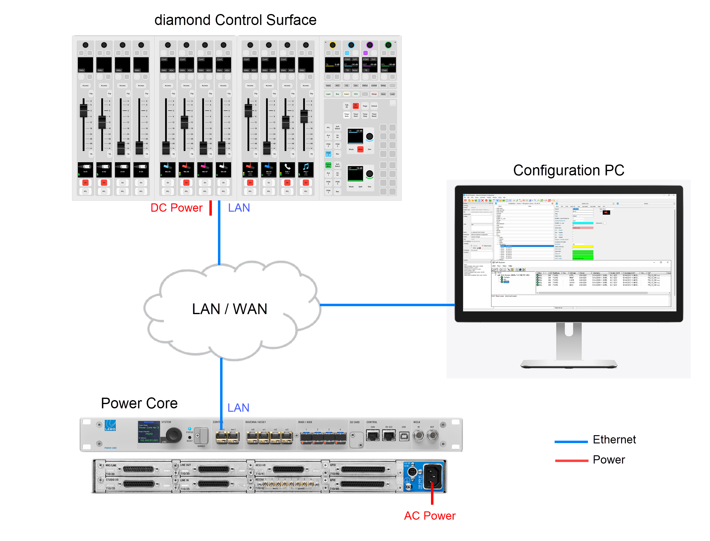
The diagram below shows the connections for a single diamond frame. The Ethernet connection can be made directly (point-to-point) but is more usual to connect via a network.
- To connect the diamond frame, use the ETHERNET port (on the underside of the frame).
- To connect Power Core, it is recommended to use the first control port: dwc0.
While the diamond frame is booting, the modules show their communication mode (on the surface displays).
- The module that sits above the frame's connector board must show CAN+IP (or IP if the frame has only one module).
- All other modules must show CAN.
If you need to reset a module's communication mode, then this can be done from the surface. See diamond - Communication Modes.
The IP connection from the surface to Power Core is configured using the "Control Interface" parameters stored on each device.
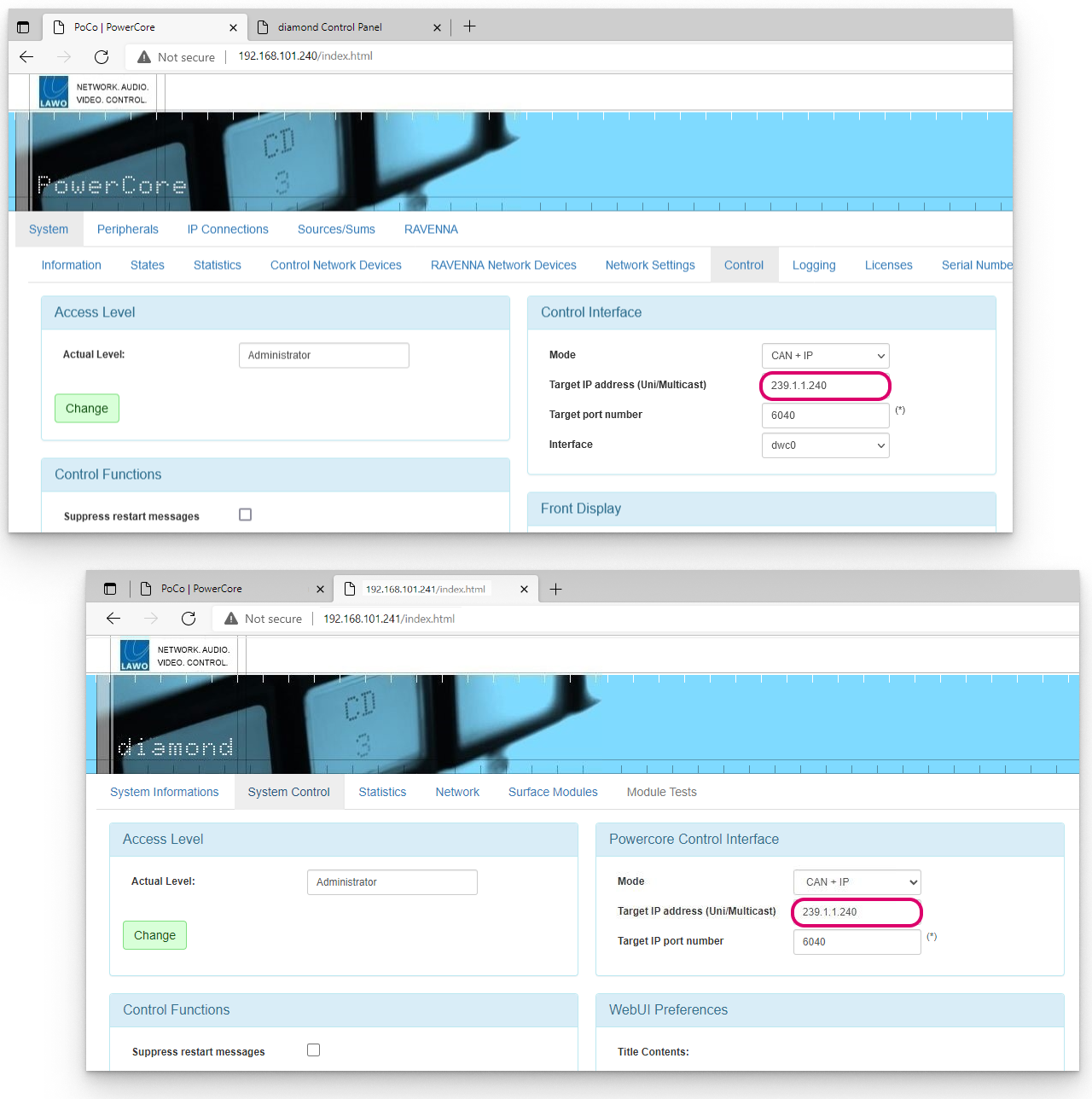
To check or edit the settings, open a Web UI connection to both the diamond frame and Power Core, and log in as either Supervisor or Administrator. Then look for the "Control Interface" parameters (in the "System → Control" tab). It is important to check both sides of the connection, so open a separate browser window for each device.
The Target IP address determines the IP address scheme.
- To use Multicast, the Target IP Addresses in Power Core and diamond must be identical. So, enter a suitable IP address group in Power Core and then copy it to diamond. The default setting is 239.1.1.240
- To use Unicast, you must enter the reciprocal IP addresses. So, enter the diamond control port IP address (in Power Core) AND enter the Power Core control port IP address (in diamond).
The other fields can be left at their default values.
If you make any changes to the "Control Interface" settings, then you must reboot the device(s).
The screenshots below shows an example of a multicast configuration using the default multicast IP address group.
If everything is correctly connected and configured, the surface synchronizes to Power Core once the IP connection is made.
Configuring a Surface with Multiple Frames
The following options apply if the diamond surface has more than one connector board. For example, if there is more than one frame OR the frame is wider than 4 modules (5ME or above).
Option 1: IP to Power Core + CAN bus daisy-chain
In this example, the first frame connects to Power Core via IP, and the second frame daisy-chains to the first using an external CAN bus cable. If you have a third frame, then it is possible to add this to the CAN A daisy-chain by re-plugging the internal CAN connectors.
This option is ideal for split frames within the same studio or wider frames with two connector boards (5ME or above).
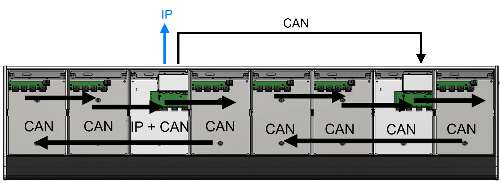
The communication modes (shown on the surface during boot-up) are similar to those on a single-frame console.
- The module above the frame's Ethernet connector board must show CAN+IP (or IP).
- All other modules must show CAN. This includes the module above the second connector board on the right of the frame.
The IP connection to Power Core is also configured in the same way as for a single-frame console, so configure the "Control Interface" settings (as described above).
Once the IP connection is configured, use a CAT 5e cable to connect CAN A on the first frame to CAN A on the second frame.
If you have a third frame, then this can be added to the daisy-chain as follows: inside the second frame, connect the internal CAN A to the CAN B output; then run an external cable from CAN B on the second frame to CAN A on the third frame.
When daisy-chaining more than one frame, the CAN A cable length must not exceed 13 meters including the internal wiring. For more information about how to calculate the CAN A bus cable length, see diamond - Wiring.
If you wish to connect a KSC or GPIO panel, then this must be connected to CAN B on the last frame. On the last key panel in the chain, fit the CAN bus terminator supplied with the system.
If everything is correctly connected and configured, the surface synchronizes to Power Core once the IP connection to the first frame is made.
Option 2: Individual IP connections to Power Core
In this example, each frame connects individually to Power Core via the IP network.
This option can be used to install frames remotely from each other in different studios / locations.
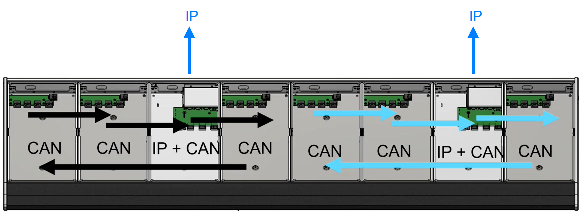
This time the communication modes (shown on the surface during boot-up) will be slightly different.
- All modules that sit above an Ethernet connector board must show CAN+IP (or IP).
- All other modules must show CAN.
For the IP connections to Power Core, it is possible to use either a Multicast or Unicast IP address scheme.
- To use Multicast IPs, the Target IP address fields in the "Control Interface" settings must be identical. Take care to check all of the diamond IP frames and Power Core. For the example above, open three Web UI sessions: one for Power Core and one for each diamond frame, and remember to reboot the devices if you make changes to the "Control Interface" settings.
- If you wish to use Unicast IPs, then this requires some additional configuration (in the ON-AIR Designer). More information will follow.
For the wiring, when frames are connected via IP, there is no need for an external CAN connection and so the CAN A ports must be terminated.
The CAN B ports can be used to connect a KSC or GPIO panel; you can make this connection from either frame. On the last key panel in the chain, fit the CAN bus terminator supplied with the system.
If everything is correctly connected and configured, each frame synchronizes independently to Power Core, This happens as soon as each IP connection is made.