diamond - Slot IDs
As part of the system setup, a slot ID must be assigned to each control surface module. This determines the functionality of the module according to the matching slot ID/address defined in the configuration.
The image below shows how this works for a diamond surface with multiple frames. You can see the ON-AIR Designer 'Frame → Surface' configuration (at the top) and the console frames (below). The slot IDs are highlighted in different colors to show the assignments to each diamond frame.
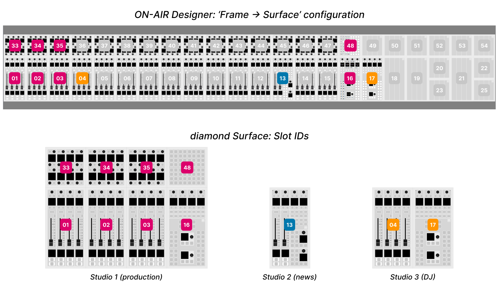
On the surface, the active slot IDs affect which fader numbers are controlled (from the Fader/Combo Modules) and which Access Group a console belongs to (via the Central/Combo Modules).
In our example, the studio 1 console controls faders 1 to 24, in two layers, (via IDs 1 to 3) and belongs to Access Group 1 (via ID 16); studio 2 controls faders 97 to 100 and belongs to Access Group 3 (via ID 13); studio 3 controls faders 25 to 32 (via ID 14) and belongs to Access Group 2 (via ID 17).
For more information about the 'Frame → Surface' configuration, please refer to ON-AIR Designer User Manual. Here we deal with the assignment of the slot IDs to the surface modules.
Important: each module's address must be unique. It is not permitted to assign the same slot ID to more than one module. If more than one module has the same slot ID, then you may see some odd behaviours once the console is operational.
How to Check and Assign the Slot ID(s)
The active slot IDs are shown on the surface displays during boot-up, and are configured using the "Surface → Modules" tab in the Web UI.
To check the settings:
- Open a Web UI connection to the diamond frame.
- Log in as either Supervisor or Administrator. The default passwords are orion for Supervisor and hydra for Administrator.
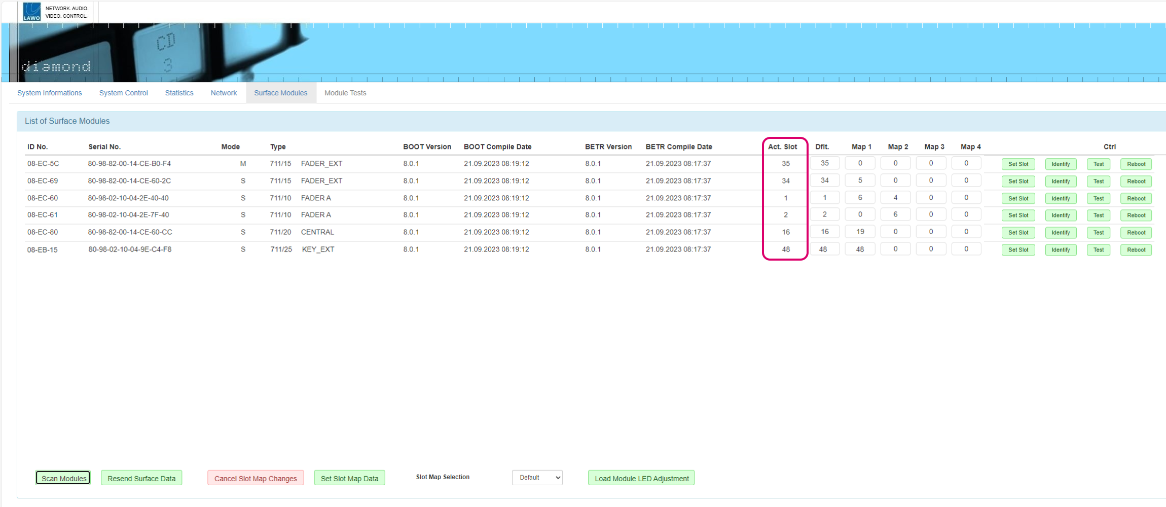
- Select the "Surface Modules" tab and look at the Act. Slot values - these show the active slot ID for each module.
The active slot ID can be changed either, permanently, by editing the Dflt (default) value or, temporarily, by loading one of the alternate mappings (Map 1 to 4).
Editing the Default Slot IDs
During the initial setup, you should use the Dflt value to assign the correct slot ID to each physical module. This is done as follows.
- Type the required slot ID into the Dflt field - the edited value and Set Slot button highlight in yellow.
- Press Set Slot to make the assignment.
- Wait for the Act. Slot field to update and check its value.
- Repeat these steps for each module.
The screenshot below shows how the Web UI looks when a default value is changed but not yet saved.

Using the Alternate Mappings
The alternate mappings (Map 1 to 4) can be used, during operation, to provide access to different sets of faders and/or central controls. For example, if an assistant has a frame with two Fader Modules, they can use mappings to access up to four different sets of faders. In this instance, the mapping data is stored globally and recalled using the Slot Map Selection option (at the bottom of the page) or via Ember+ (for more convenient control).
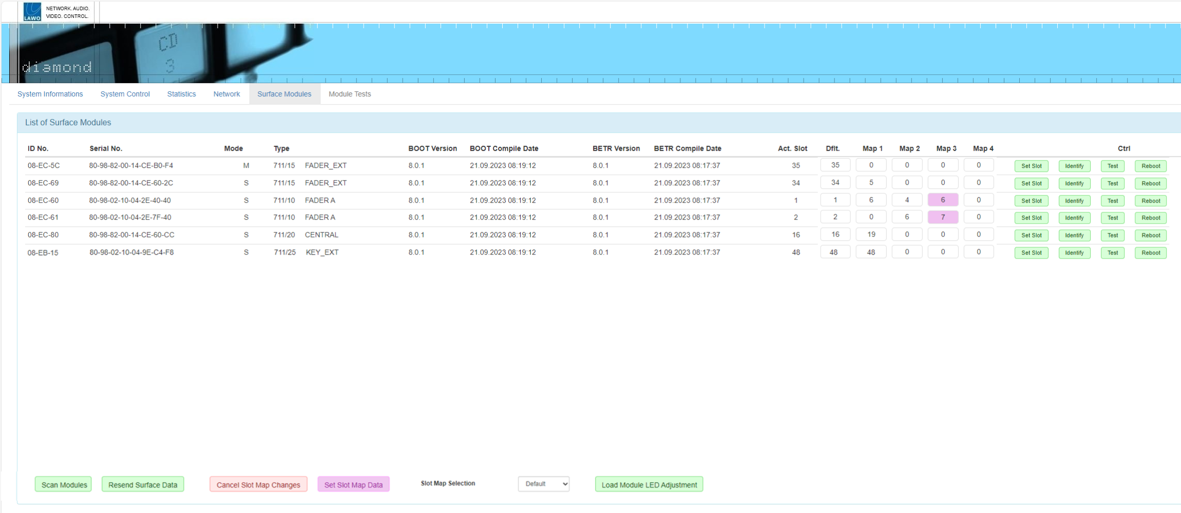
- Start by entering the required slot IDs into the Map # fields - the edited values and Set Slot Map Data button highlight in magenta.
- To save all of the changed values, press the Set Slot Map Data button. (Or to cancel all changes, press Cancel Slot Map Changes).
- To load a mapping, click on Slot Map Selection and choose an option from the drop-down menu. You can choose any of the four alternate mappings (Map 1 to 4) or revert to the Default slot IDs (defined in the Dflt fields).
- Wait for the Act. Slot fields to update and check their values. Note that all zero (0) values are ignored.
The screenshot below show how the Web UI looks when some of the mapping values are changed but not yet saved.
 The screenshot below shows the options in the Slot Map Selection menu. Once an option is selected, the active slot IDs update to match. So, in this example, the Act. Slot and Dflt values should be the same.
