diamond - Setup Quick Start
This topic describes the recommended workflow to configure a system from scratch.
Prerequisites
The instructions below assume that the customer is connecting a single diamond frame to Power Core. The connection must be made via TCP/IP Ethernet, either directly or via a network (LAN or WAN).
When connecting via a network, it is expected that all switches/routers meet the control network requirements described here.
If the diamond surface consists of more than one frame, then you will need to decide how to connect the additional frames: either via CAN bus (to the main frame) or via IP (to the network). All possible options are explained here.
The IP connection(s) to Power Core may use either a Multicast or Unicast IP address scheme. If you wish to use Unicast IPs for more than one frame, then this requires some additional configuration (in the ON-AIR Designer).
Instructions
To set up the system you will need a PC that is installed with a suitable web browser and Lawo's ON-AIR Designer software. How to prepare the configuration PC is described later in diamond - Configuration Tools.
1. To boot and configure the system, the following connections must be made:
- The diamond frame must be grounded.
- The diamond frame must be connected via Ethernet to the network/Power Core.
- Both components must be powered.
Once power is applied, the system boots in a few seconds:
- On the surface, the displays show information about each module and then, after a few seconds, the Lawo logo.
- On Power Core, the boot-up progress is shown on the front panel display.
While the diamond frame is booting up, check the communication modes shown on the surface displays:
- The module that plugs into the frame's IP connector board must show CAN+IP (or IP if the frame has only one module).
- All other modules must show CAN.
If you need to reset a module's communication mode, then this can be done from the surface. See diamond - Communication Modes.
2. Start the configuration by connecting your PC's LAN port directly to diamond frame.
This is done using the frame's ETHERNET port. For the cabling and network requirements, see diamond - Wiring: ETHERNET.
3. Configure the network settings for the frame's IP module.
This step is necessary if you wish to fit diamond into an existing network OR install more than one device (to avoid IP conflicts).
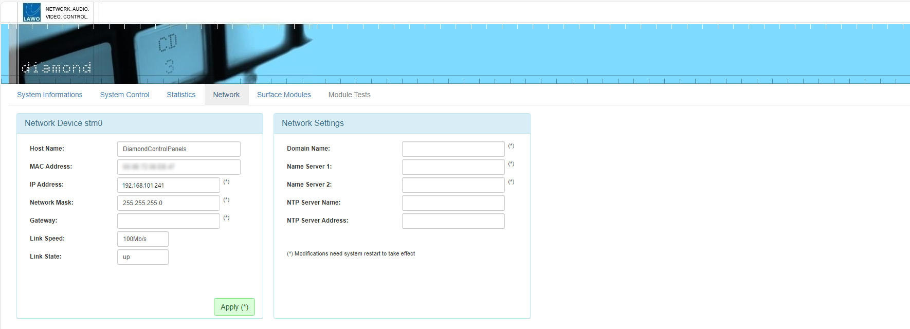
The settings are edited by opening a Web UI connection to the frame and adjusting the parameters in the "Network" tab.
- The Web UI can be reached by entering the current IP address: 192.168.101.241
- Log in as either Supervisor or Administrator. The default passwords are orion for Supervisor and hydra for Administrator.
- Open the "Network" tab and enter the required network settings.
The following fields can be edited: IP Address, Network Mask and Gateway. Type in the new value(s) and select Apply to save the changes.
The screenshot below shows an example.
At this stage, you can reconnect your devices via the control network OR continue on (if you plan to connect the frame directly to Power Core).
It is recommended to check the network connection to your configuration PC by re-opening the diamond Web UI.
4. Configure the surface modules.
This step ensures that the IP module knows about all other modules in the frame, and that the correct slot IDs are assigned.
Start by opening the "Surface Modules" tab in the diamond Web UI - you will see all modules connected to the IP module (via high-speed CAN). If the list is empty, press the Scan Modules button (at the bottom of the page).
The screenshot below shows an example where the frame is populated with six modules.

The Mode column can be used to identify the master (M) module. This is the module that connects to Power Core via IP. During boot-up, the communication mode of the master module must show as CAN+IP (or IP if the frame has only one module). All of the slave (S) modules must be set to CAN. If you need to reset a module's communication mode, then this can be done from the surface. See diamond - Communication Modes.
The Act. Slot column shows the module's active slot ID. This is important as it determines the functionality of the module (as explained later).
During the initial setup, you should use the Dflt value to assign the correct slot ID to each physical module.
- Start by entering the required slot ID into the Dflt field - the edited value and Set Slot button highlight in yellow.
- Press Set Slot to make the assignment.
- Wait for the Act. Slot field to update and check its value.
- Repeat these steps for each module.
Note that the alternate mappings (Map 1 to 4) can be used to change the slots ID during operation. For now, it is recommended to leave these values at 0.
5. Configure the IP connection between the diamond frame and Power Core.
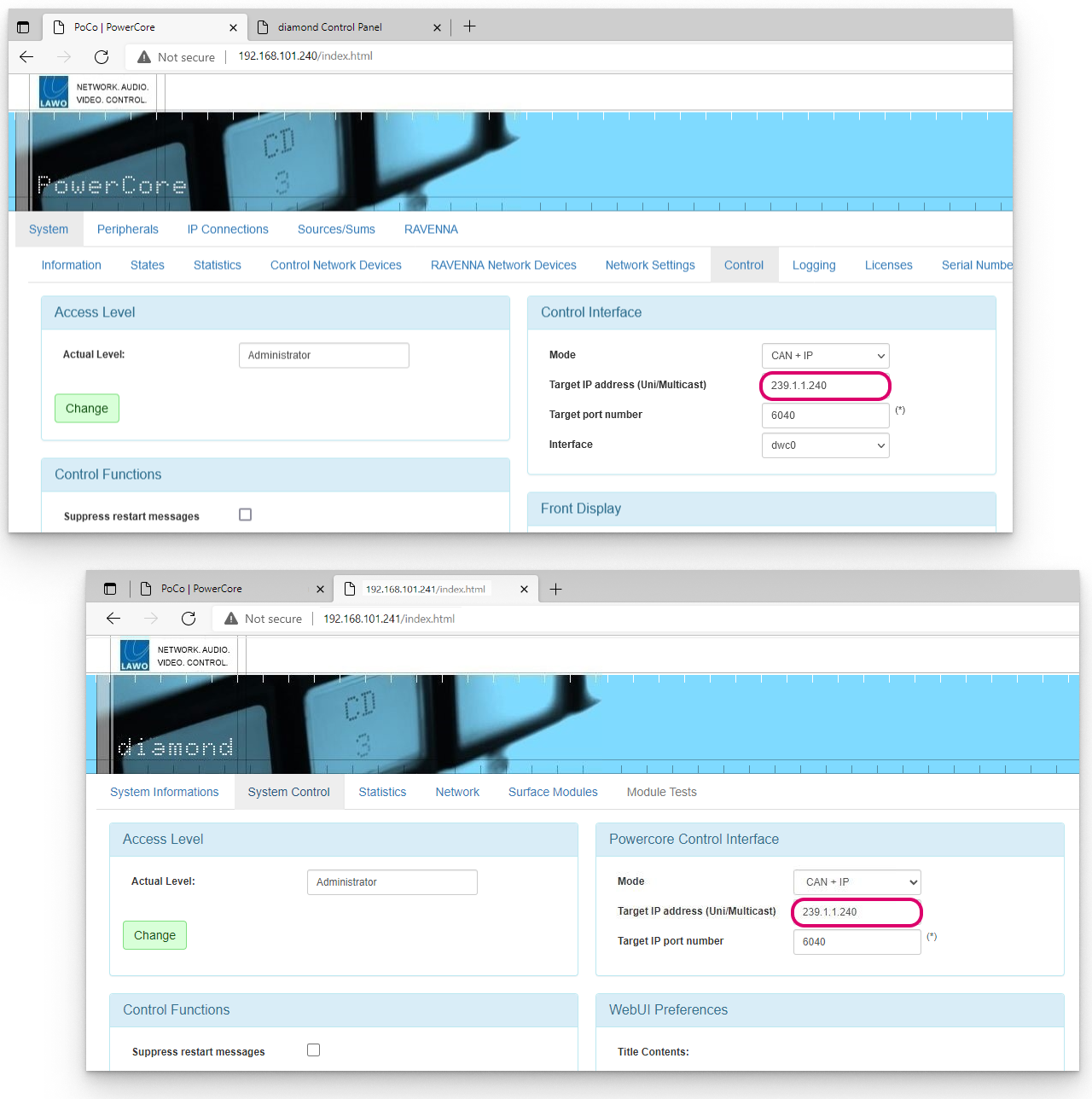
This is done by opening a Web UI connection to both the diamond frame and Power Core. Then editing the "Control Interface" parameters (in the "System → Control" tab). It is important to check both sides of the connection, so open a separate browser window for each device.
The Target IP address determines the IP address scheme.
- To use Multicast, the Target IP Addresses in Power Core and diamond must be identical. So, enter a suitable IP address group in Power Core and then copy it to diamond. The default setting is 239.1.1.240
- To use Unicast, you must enter the reciprocal IP addresses. So, enter the diamond control port IP address (in Power Core) AND enter the Power Core control port IP address (in diamond).
The other fields can be left at their default values.
If you make any changes to the "Control Interface" settings, then you must reboot the device(s).
The screenshots below shows an example of a multicast configuration using the default multicast IP address group.
If everything is correctly connected and configured, the surface synchronizes to Power Core once the IP connection is made.
6. Once the IP connection to Power Core is established, the basic setup of the diamond surface is complete.
The next steps are to check the software version(s) running on the hardware components, activate the license(s) and upload a configuration. These are done in the same way as for any other Power Core system, so please follow the links below for more information.
- Start by using SoP Explorer to upgrade Power Core to the required software release. See Power Core - Updating the Firmware.
- Activate the software license(s) using the online license portal. The license(s) must be installed onto the USB memory stick that connects to the Power Core DONGLE port. See Power Core - License Activation.
- Using ON-AIR Designer, create a diamond configuration and export it to Power Core (via "Transfer Config to Unit"). The configuration does not have to be the final version, but should define the correct surface layout and main license package. See Power Core - Uploading a Configuration.
- Return to SoP Explorer and check that it can see the surface.
- Finally, use SoP Explorer to check the status of the surface components. If upgrades are required, run the "Software Update Wizard" until all surface components are shown in green.
Important: When preparing the system configuration, please note the following points.
- It is important that the configured options match the licensed feature set. Otherwise, if the license limits are exceeded, the Power Core alarm will sound.
- Never assign a Central and Combo module to the same DSP access group. If both modules are fitted, one must be configured to run in monitor mode.
Next Steps
Once you have completed the steps above, the system is ready for operation.
You can use the "Surface Modules" tab (in the diamond Web UI) to check the status of the individual modules.
Then go to diamond - Operation to learn more about the functionality of the device.
Troubleshooting
This message appears if there is a problem with the network connection to Power Core.
- Check the network cabling and IP addresses of the surface and Power Core.
- Check the "Control Interface" settings in both the surface and Power Core.
- Check that the module above the frame's connector board is fitted correctly, with all screws tightened. If the screws are not fixed properly, then the module may not be plugged fully into the connector board underneath. This can lead to an intermittent network connection.