Power Core - Configuring the System
This topic describes how to customize the functionality of Power Core using ON-AIR Designer.
It is assumed that you have installed the software and have a valid network connection to the system (as described here).
Overview
In both cases, you must use ON-AIR Designer to prepare a project offline. Then open a valid network connection to the core, to create and transfer the new system file(s). You will need to do this during the initial setup to get the system operational, and subsequently to make changes to the functionality.
What you will need
To modify an existing configuration, you will need a copy of the current project as a .db3 (or .mdb) file.
For Power Core systems, it is recommended to retrieve a copy of the project stored on the device (using 'File → Load Project from Unit'). Alternatively, you can use one of the standard configurations available from the Downloads area at www.lawo.com (after Login).
If you plan to use VisTool with your device, then it is a good idea to edit the VisTool and ON-AIR Designer configurations in parallel. For more information on editing a VisTool project, see the VisTool documentation.
First Steps
You can check the version of ON-AIR Designer while the software is starting. It can also be checked later (by selecting Help → Info).
At the top of the page you will find the main menus and toolbar.
To start working with the software, you will need to open a project. Multiple instances of ON-AIR Designer can be open at the same time (to work on several projects simultaneously).
Please note: It is not possible to open multiple projects within a single ON-AIR Designer instance nor to edit a single project from multiple ON-AIR Designer instances.
To open a project, use one of the following methods:
- File → Load Project from Unit - downloads a copy of the project stored on the device (recommended).
- File → Open - opens an existing project stored locally on your computer.
- File → New - creates a new configuration using the 'New Project Wizard'.
Please click on the links above for full instructions.
Editing the Project
Once a project is open, it can be edited and then saved (offline).
In the example below, the three docking areas are outlined in blue and the floating windows are outlined in red. How to customize the layout is described later. First, we describe the functionality of the configuration tools.
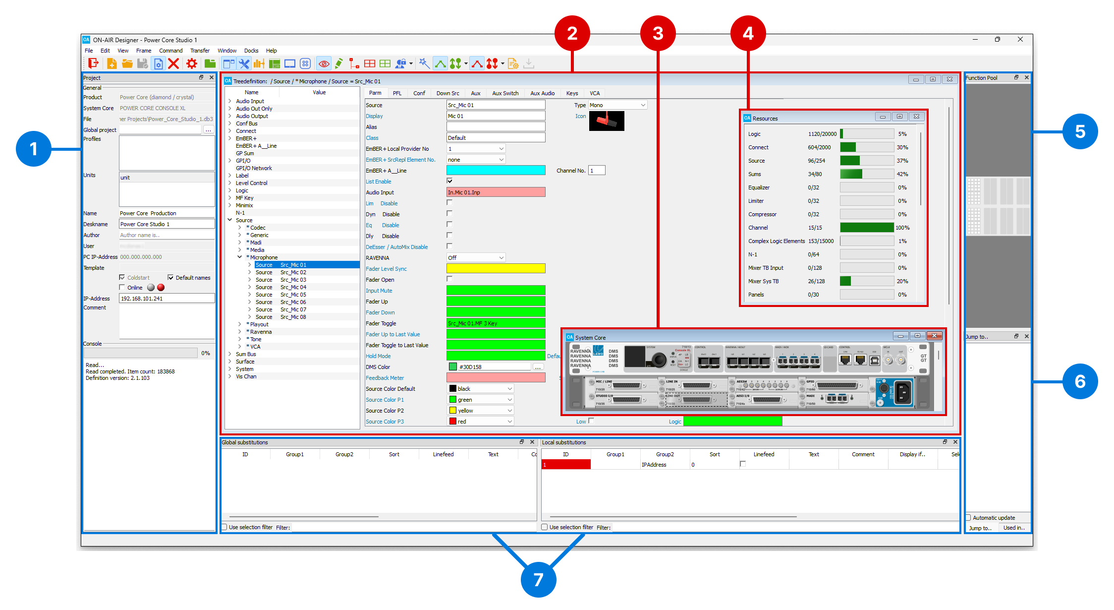
1. Project
The 'Project' window defines the general properties of the system. These include the Product description, System Core type, etc. If more than one Unit is defined, then it is possible to use substitutions (to configure multiple systems).
From here, you can also make an Online connection to the selected unit, and view the progress of operations such as load, save and transfer.
2. Treedefinition
The 'Treedefinition' is used to specify all the elements of the system, from sources and buses to MF Keys and logical functions. Once the hardware is configured (using the Frame windows), this is where most of the work is done.
Each of the branches (on the left) represents an element, or element group. To navigate around, either double-click on a branch name or use the open/close arrows. To insert, copy or delete an element, right-click on a branch.
Once an element is selected, its parameters appear (on the right) - in our example, for the source named Src_Mic 01. Use the tabs (at the top of the parameter area) to select a page. Then edit the parameter fields. If a field has a color, then it can be linked to another element in the configuration. In this instance, the colors indicate the expected signal type: red for an audio signal; green for a logical function; yellow for a variable control; and so on.
To make an assignment: double-click (inside) the field to open a 'Treeselection' dialog; locate the signal you wish to assign and select OK to confirm. In the example above, the mic 01 source Fader Toggle function is triggered by the mic 01 source MF Key 3.
3. Frame → System Core
The 'Frame' windows define the system components, and ensure that the correct parameters appear in the 'Treedefinition'.
There is a separate window for each component: the System Core (the DSP Core), Surface (the control surface), Panels (any optional key panels) and Screen (for VisTool functions).
In each case, you will see a graphical representation. Right-click to configure an option - for example, to add an expansion I/O card to the 'System Core'. Once the option is configured, the 'Frame' updates and any changes are reflected in the 'Treedefinition'.
Important: Each frame must be configured correctly to ensure that all permitted options are available in ON-AIR Designer.
For Power Core, please pay attention to the hardware revision and licenses. If the configured licenses (in ON-Air Designer) exceed what is available (on the license dongle) then, once the configuration is uploaded, the Power Core alarm will sound.
4. Resources
The 'Resources' window can be used to check the amount of DSP resource used by the project.
The counters show how many resources are left out of the maximum available. For Power Core systems, the maximum numbers vary depending on the main license. Note that the add-on license resources such as N-1 and Mixer TB Input are displayed regardless of whether the add-on is enabled or disabled.
If you try to add a resource which exceeds any of the limits, the software warns you by displaying the message: 'No resources available'.
5. Function Pool
When configuring a surface, the 'Function Pool' can be used to move a function or prepare MF Keys before positioning them on a module. This is ideal if you know what functionality is required, but are not yet sure of the MF Key layout.
6. Jump to, Used in & Parameter Line
The following functions can be used to interrogate the 'Treedefinition'. In each case, the panel can be opened in the docking area on the right or floated above the central workspace.
- Jump to.. shows all occurrences of a reference (in the 'Jump To' docking panel). When using substitutions, it can be combined with Used in...
- Parameter Line shows all available options for a parameter (in the 'Parameter Line' docking panel).
7. Substitutions
If you are configuring more than one unit, use the 'Global' and 'Local' substitution windows to individualize parameters as required. In the other configuration windows, a substituted parameter is indicated by a colored frame and grey background. To learn more about this feature, please Configuring Multiple Systems.
Inputs and Outputs
The Command → Inputs and Command → Outputs windows list all of the configured inputs and outputs including any loopbacks.
From here, you can edit the same I/O parameters as in the "Audio Input" and "Audio Output" branches of the 'Treedefinition', but in list form. This can often be quicker than using the 'Treedefinition' if you have lots of signals to reconfigure.
Saving the Project
It is recommended to use "save as" regularly, to keep a copy of the project at different revision stages. This allows you to revert to an earlier version if, during testing, any mistakes are found.
To overwrite the current project, use one of the following methods.
- Select File → Save from the main menus.
- Click on the
 Toolbar icon.
 - Press CTRL + S on your computer keyboard.
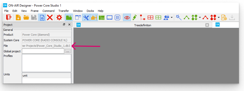
This overwrites the current file (specified in the "File" field in the 'Project' window).
To save into a new project file, use "save as" as follows.
1. Open the "Save" dialog box using either of the following methods.
- Select File → Save As... from the main menus.
- Press CTRL + SHIFT + S on your computer keyboard.
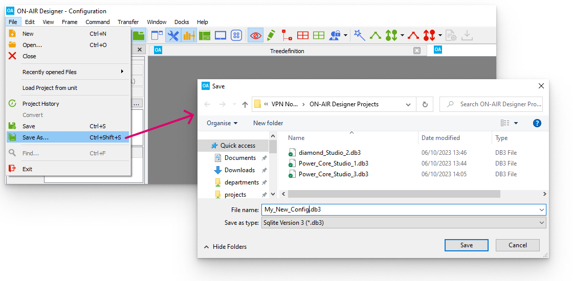
2. Choose a folder location and enter a suitable file name.
The default file type is .db3 which is fine for all current products.
For compatibility with legacy systems, the file type can be changed to .mdb using the Save as type option at the bottom of the dialog box.
Note that a project containing substitutions cannot be saved as a .mdb file.
3. Select Save to save the file.
Uploading the Configuration
Once you have finished editing the project, it is time to transfer the configuration back to the Core. This is done using Transfer → Config to unit.
Important:
- At the end of the transfer, Power Core will cold start. Please make sure that the system is NOT in use before starting the transfer.
- The transfer will replace the existing configuration stored on the device. Please make sure you have a backup of the existing project before proceeding.
To perform the transfer, you must have a valid network connection to the device:
- Use the Online status indicator (and IP Address field) in the 'Project' window to check the network connection (as described here).
- If there is a problem with the network communication, then the Transfer → Config to Unit option is greyed out.
![]()
1. In the 'Project' window, select the unit from the Units field (if multiple units are configured).
2. Tick the Online checkbox and make sure that you have a valid network connection to the device - the green indicator must be lit to continue.
If the red indicator is lit, then check the IP address of the device and edit the IP-Address field to match - the online indicators will update.
3. If any changes have been made to the configuration, then these must be saved before the transfer.
Use either "File → Save" or "File → Save As" to save the project. You can use any file name and location.
If you edit the IP Address field in the 'Project' window, then the file must be saved, closed and re-opened.
4. Select Transfer → Config to unit from the top menu bar, or click on the ![]() Toolbar icon - a confirmation box appears.
Toolbar icon - a confirmation box appears.
5. Check the details and select Yes to start the transfer.
The software now compiles the necessary files and transfers them to the device. The progress is shown in the Console status area at the bottom of the 'Project' window.
Once the transfer is complete you will see the lines "File loaded to unit" and "Sending restart". The device will go offline while it restarts. This is perfectly normal but may take a few seconds.
6. The new configuration data is loaded at the end of the boot-up sequence and the transfer is complete.
If your computer's firewall prevents the transfer, then change your firewall settings and retry.
7. You should now test the operation thoroughly to check that the system is working as expected.