diamond - Cabling Considerations
All external connections are made to the frame's connector board which is located on the underside of the frame.
Connector Board Position
The connector board can be located beneath any module and its position is specified at the time of order. The images below show two examples: a standard frame (on the left) and extended frame (on the right). The position of the frame's IP module/connector board is highlighted in red.
|
|
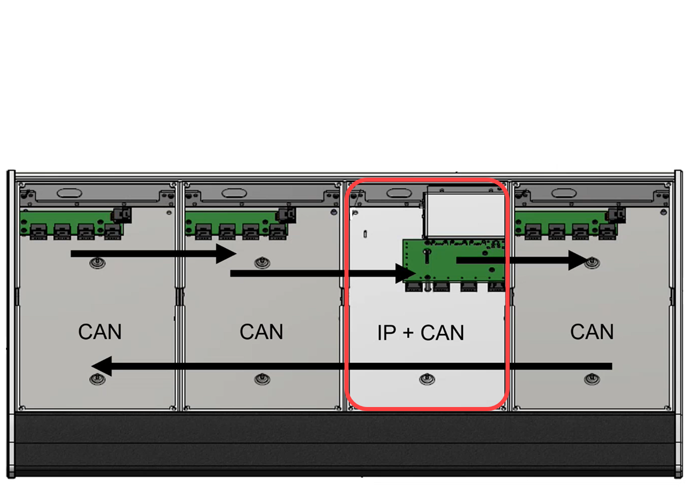
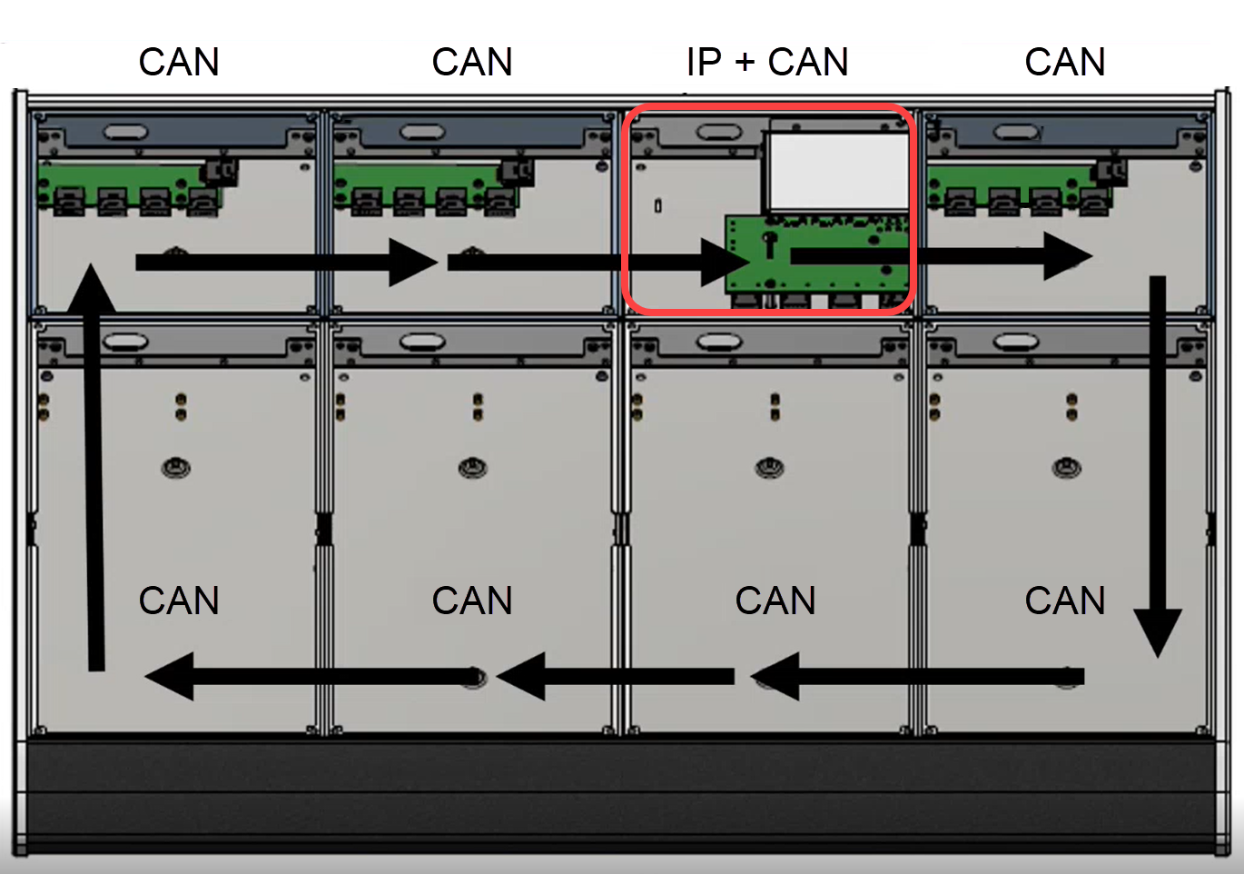
When specifying the position, please consider the following points.
- All external cabling is made to the frame's connector board, so you must make sure that the cable tray is accessible.
- The slot above the connector board must be fitted with an active module (and not an empty slot / blind plate). This is because the ETHERNET connector on the board plugs into the module above. So if there is no module, then the ETHERNET port is inactive.
- For frame widths of 5 ME or above, a second power distribution and connector board are required. In this instance, a second external power supply is provided and the two parts of the frame must be connected externally. There are two possibilities:
- The first part of the frame connects to Power Core via IP, and the second part daisy-chains to the first using an external CAN bus cable. Usually, this is the preferred option.
- Each part of the frame connects individually to Power Core via IP.
- If the surface consists of more than one frame, then the additional frames are treated in a similar manner: either each frame can connect individually to Power Core (via IP) or daisy-chain to the main frame (via CAN bus).
Internal Wiring
Internally, the control surface modules are connected via high-speed CAN in a daisy-chain fashion.
- The CAN bus wiring starts from the termination on the frame's connector board, and then daisy-chains to and from each module, before returning to CAN A on the connector board.
- Each module has three wired connections: 1 x power to the frame's power distribution board, and 2 x CAN bus to the next/previous module.
- For the module that sits above the frame's connector board, there is a fourth connection to the external Ethernet port. This connection is made by a series of pins on the underside of the module that plug into the connector board when the module is mounted into the frame. This is why it is important that a module is always fitted to this slot position (to ensure that the external Ethernet connection to Power Core can be made).
As part of the system setup, a communication mode must be selected for each control surface module. There are three possible options: CAN, IP or CAN+IP.
For more information about how to configure the communication modes, and the IP connection to Power Core, see the System Setup chapter.