Power Core RP v2 - System Settings
MADI Mode Configuration
The front panel MADI Ports in Power Core RP v2 can be configured independently or can act as a redundant pair.
1. Navigate to the Tree Definition window in ON-AIR Designer (Command > Treedefinition in the top menu bar). Expand the System folder, select the Definition sub-folder, then select the MADI tab.
To configure MADI Front Port 1 and 2 as a redundant pair, check the P2 Tx = P1 Tx box. To configure MADI Front Port 3 and 4 as a redundant pair, check the P4 Tx = P3 Tx box.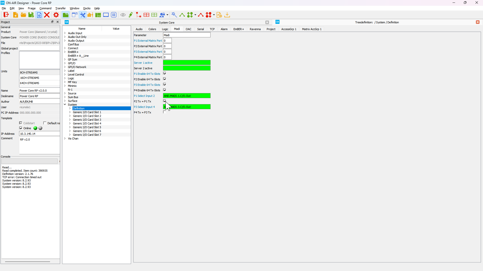
If only one redundant MADI pair will be configured MADI Front Port 1 and 2 must be used.
2. In the Tree Definition window expand the Logic folder, then select the Button 16 element named BT16.SYSTEM.MADI.MODE in the MADI Mode Configuration sub-folder.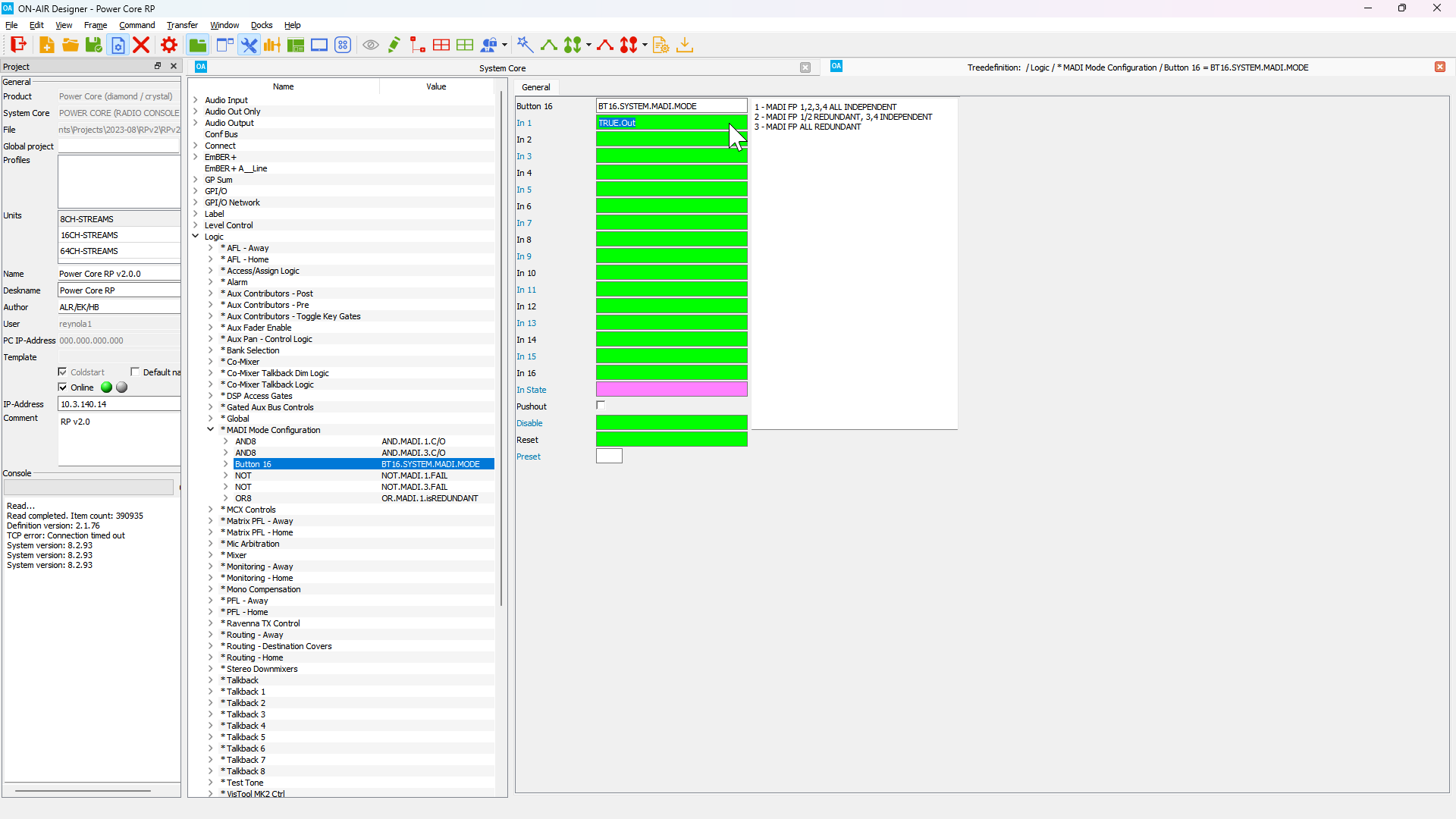
The MADI redundancy mode is set by changing the input to the Button 16 element. By default, a True logical input is assigned to Input 1, which indicates that all four MADI Front Ports are independent.
Move the True logical input to Input 2 to configure MADI Front Port 1 and 2 as a redundant pair, with MADI Front Port 3 and 4 as independent ports.
Move the True logical input to Input 3 to configure MADI Front Port 1 and 2 as a redundant pair, with MADI Front Port 3 and 4 as a second redundant pair.
3. To change the logical trigger for a Button 16 input, double click on the green field corresponding with the Input you wish to trigger. This will open the Tree Selection window. Navigate the tree to the Global folder, expand the NOT element labeled TRUE, and select the TRUE.Out element.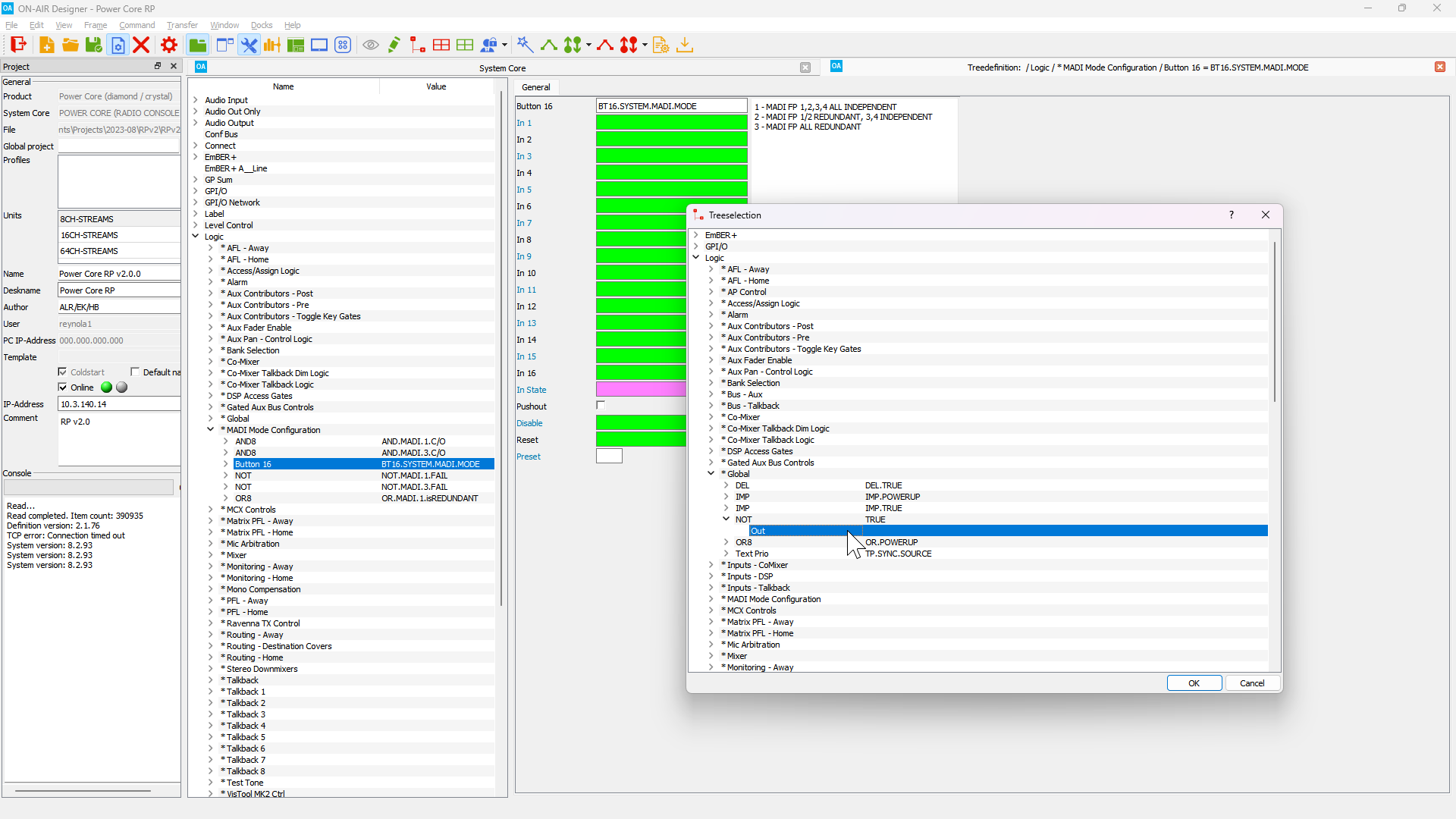
To delete a logical trigger from a Button 16 input, click on the green field containing the trigger and press the DELETE key. 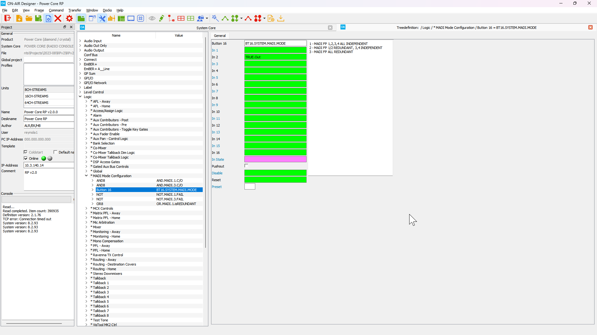
PTP Settings
It is often necessary to change the PTP domain used by the Power Core RP v2, or to configure the system as a PTP master.
New PTP settings may be entered in the Web UI, however changes made in the Web UI are only temporary and will be reset after the next coldstart.
To permanently change the Power Core RP v2 PTP Settings the ON-AIR Designer configuration file must be edited.
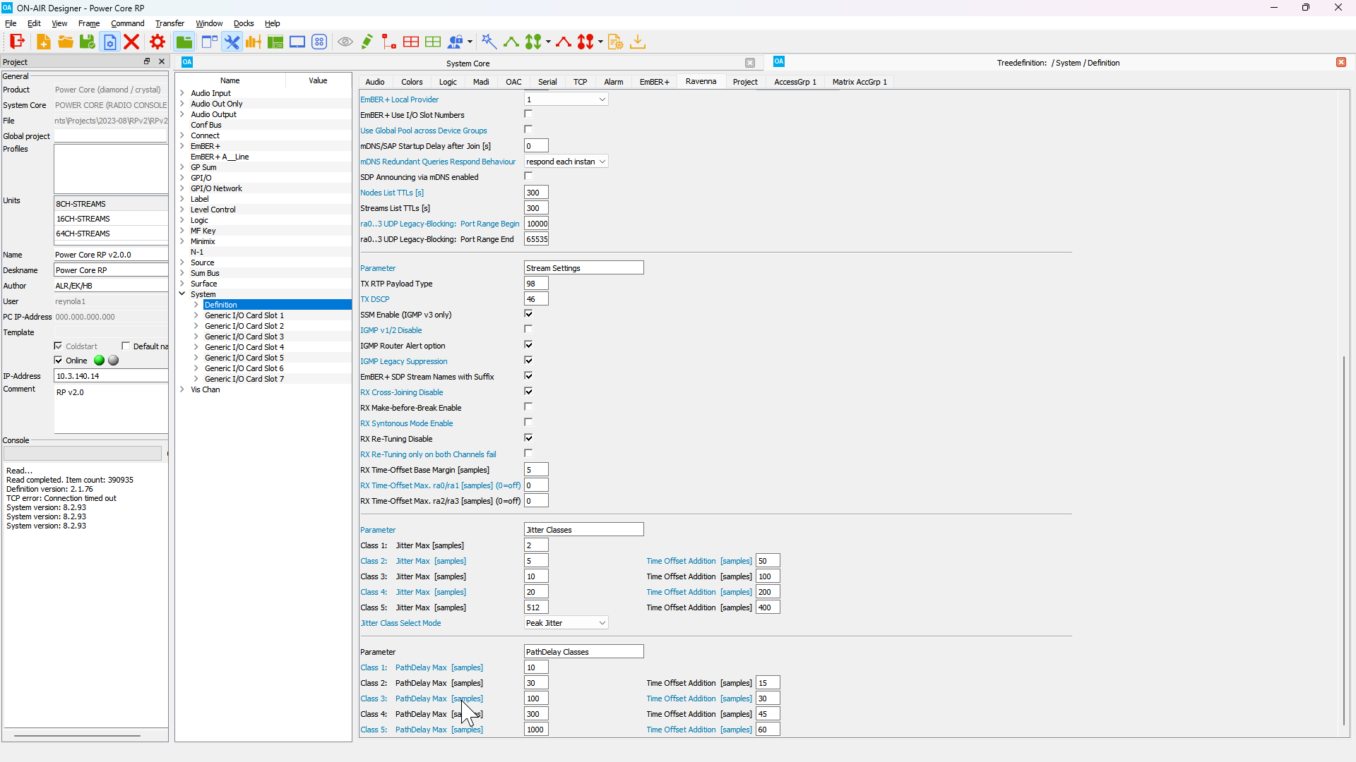
Navigate to the Tree Definition window in ON-AIR Designer (Command > Treedefinition in the top menu bar). Expand the System folder, select the Definition sub-folder, then select the RAVENNA tab. The PTP Settings section contains all PTP related parameters. 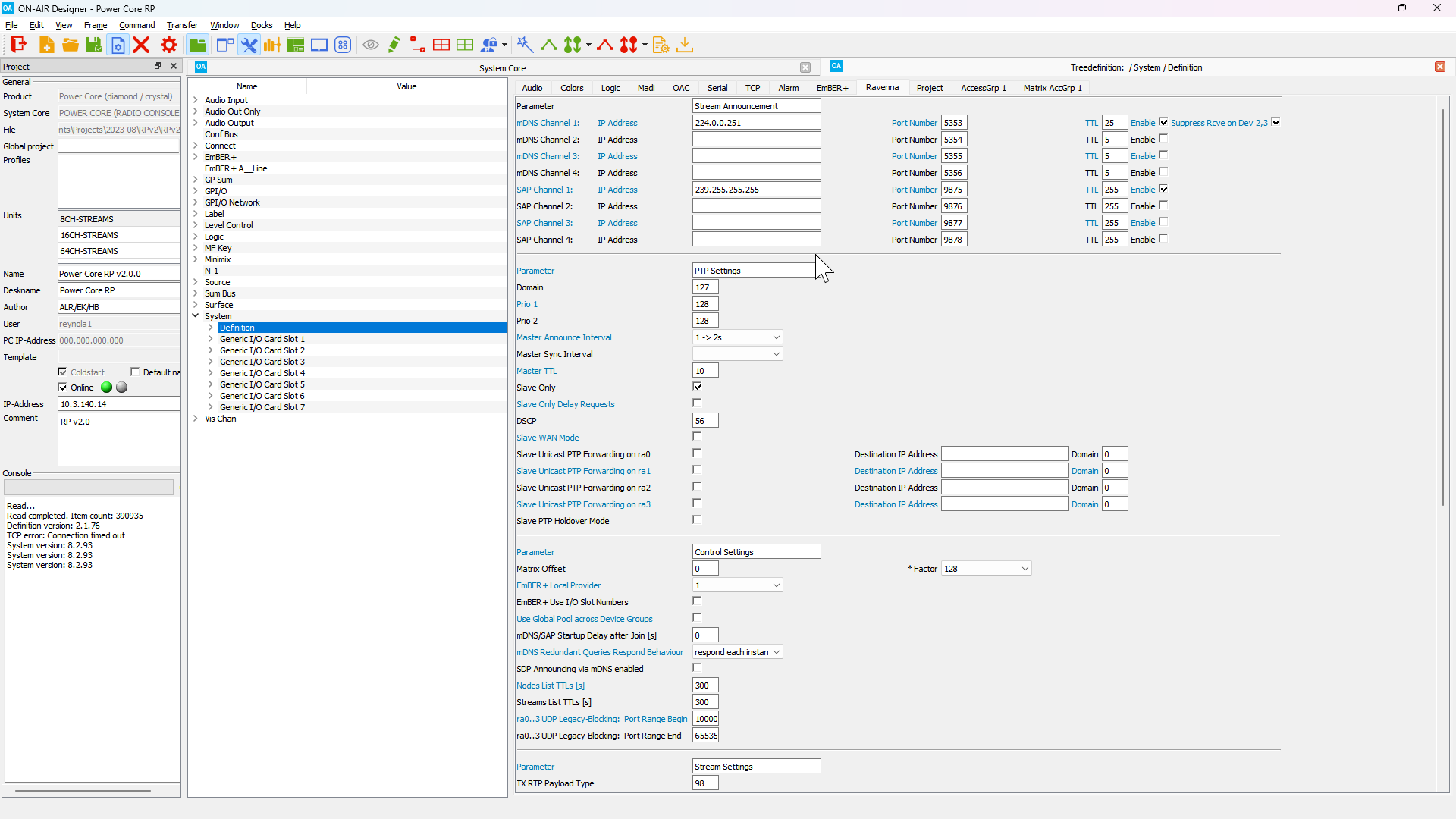
Network and RAVENNA Settings
Global network and RAVENNA settings can be configured in ON-AIR Designer.
Navigate to the Tree Definition window in ON-AIR Designer (Command > Treedefinition in the top menu bar). Expand the System folder, select the Definition sub-folder, then select the RAVENNA tab.
In the Stream Announcement section, the following parameters may be configured:
- mDNS Channel 1-4 - Set the multicast IP address to be used by mDNS advertisements. The default address is 224.0.0.251, however it is possible to use a custom multicast address in situations when routed mDNS advertisements are necessary.
- SAP Channel 1-4 - Set the multicast IP address to be used by SAP advertisements. The defualt address is 239.255.255.255.
Custom multicast addresses for mDNS and SAP advertisements are not standardized and may not be supported by other vendors.
In the Stream Settings section, the following parameters may be configured:
- TX RTP Payload Type - Set the RTP payload type for all streams generated by Power Core RP v2.
- TX DSCP - Set the DSCP value for all streams generated by Power Core RP v2.
- SSM Enable (IGMP v3 only) - Set this for environments with a IGMPv3 querier or when only source specific multicast joins should be sent.
- RX Syntonous Mode Enable - Set this to enable syntonous mode for all stream receivers
- RX Time-Offset Base Margin - The minimum time offset to be used for all stream receivers. Useful to ensure a minimum time offset when operating in Syntonous mode.
- RX Time-Offset Max. ra0|1/2|3 - The maximum time offset that may be set for any stream received on the corresponding device group.