Power Core RP v2 - Audio I/O Configuration
Adding an Audio IO Extender
The audio (and GPIO) capabilities of Power Core RP v2 can be expanded further by adding one or more Audio I/O Extenders.
For more information about the Audio IO Extender, see Power Core RP v2 - Audio I/O Extender.
To add an AIOX unit to the Power Core RPv2, the MADI port the AIOX will be connected to must be changed to an AIOX port.
1. Navigate to the System Core page in ON-AIR Designer. (Frame > System Core in the top menu bar). 
2. Right click on the MADI port that will be used to connect the AIOX and select AIOX Interface Port. ON-AIR Designer will make a series of database changes, this may take a few seconds. 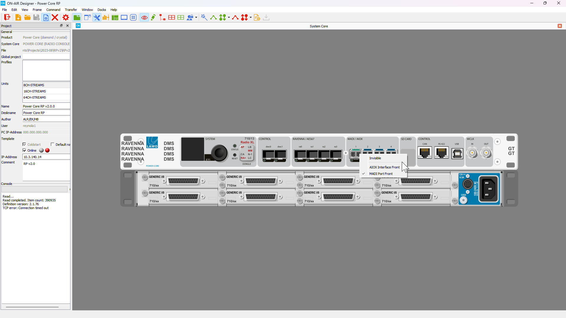
3. Once the AIOX has been added, you will see the AIOX appear underneath the Power Core. 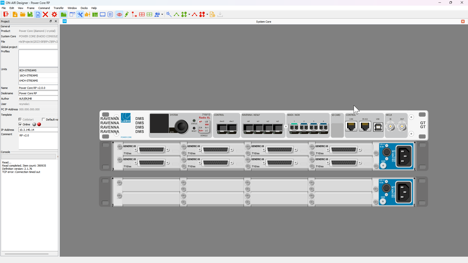
4. Right click on each of the IO card slots in the AIOX and select Generic I/O Card. By using the Generic I/O card, any type of card can be physically installed and hot-swapped.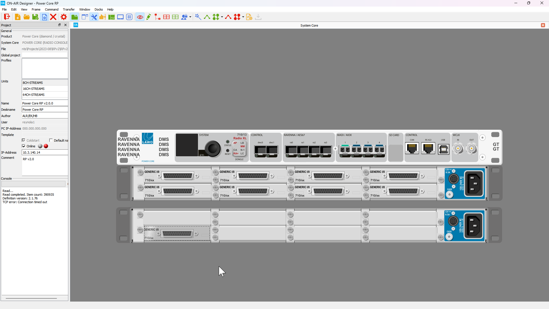
5. If you wish to configure a redundant connection to the AIOX, repeat Steps 2-4, this time choosing the next available AIOX/MADI port. For example, if the AIOX is connected to MADI Front Port 1, the redundant connection will use MADI Front Port 2.
6. Once all I/O cards have been added, signal names must be defined for the I/O channels. To do this, open the Tree Definition window (Command > Treedefinition in the top menu bar).
With the Tree Definition window open, expand the Audio Input folder and select the first Generic I/O Card in the AIOX. 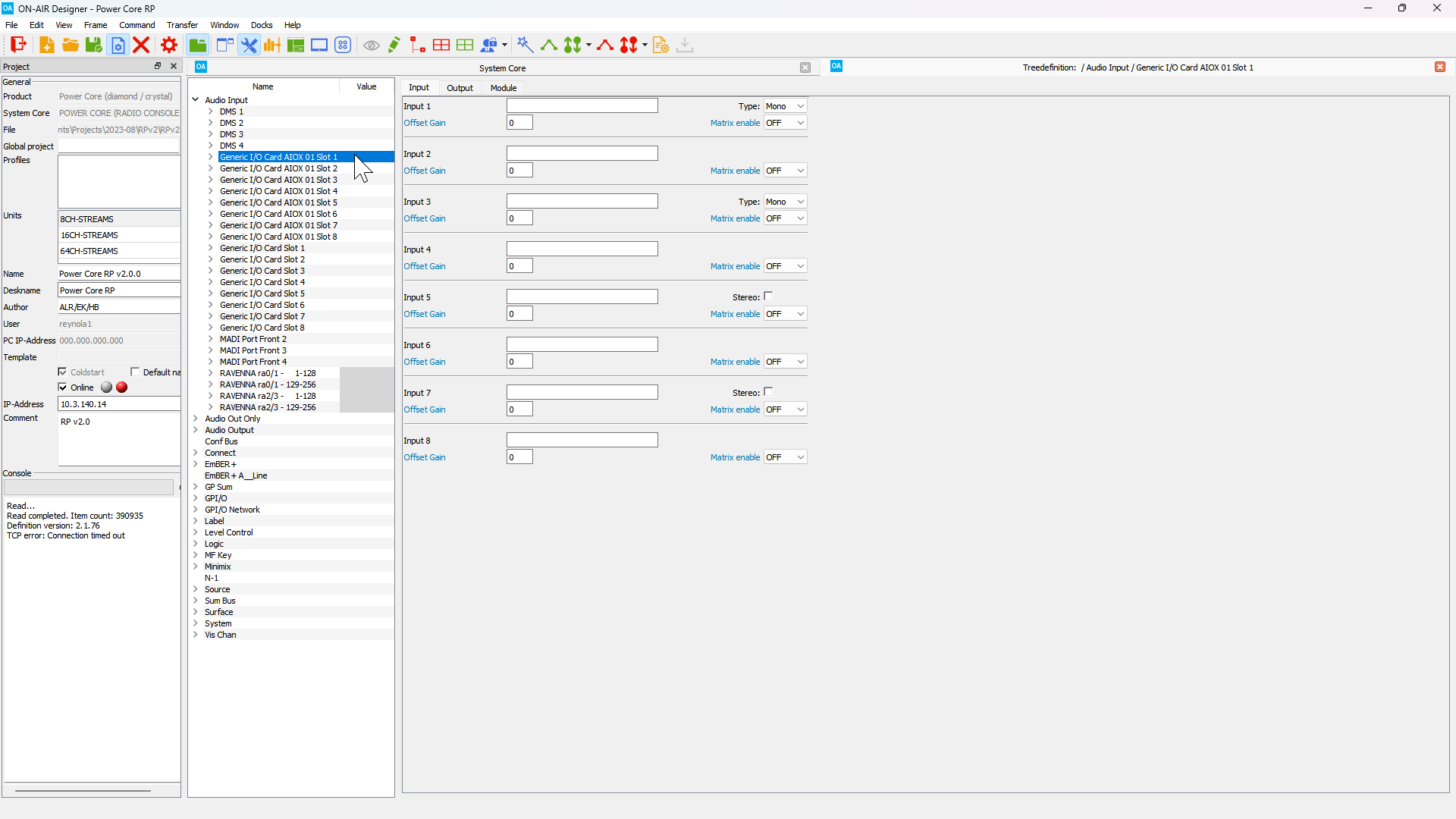
7. Each Input signal must have a label defined. Labels should follow the form GROUP.NAME where the Group and Name labels are both 8 characters or less.
Names should not start with a number and should only include alphanumeric characters (A-Za-z0-9). Underscores and dashes are also supported.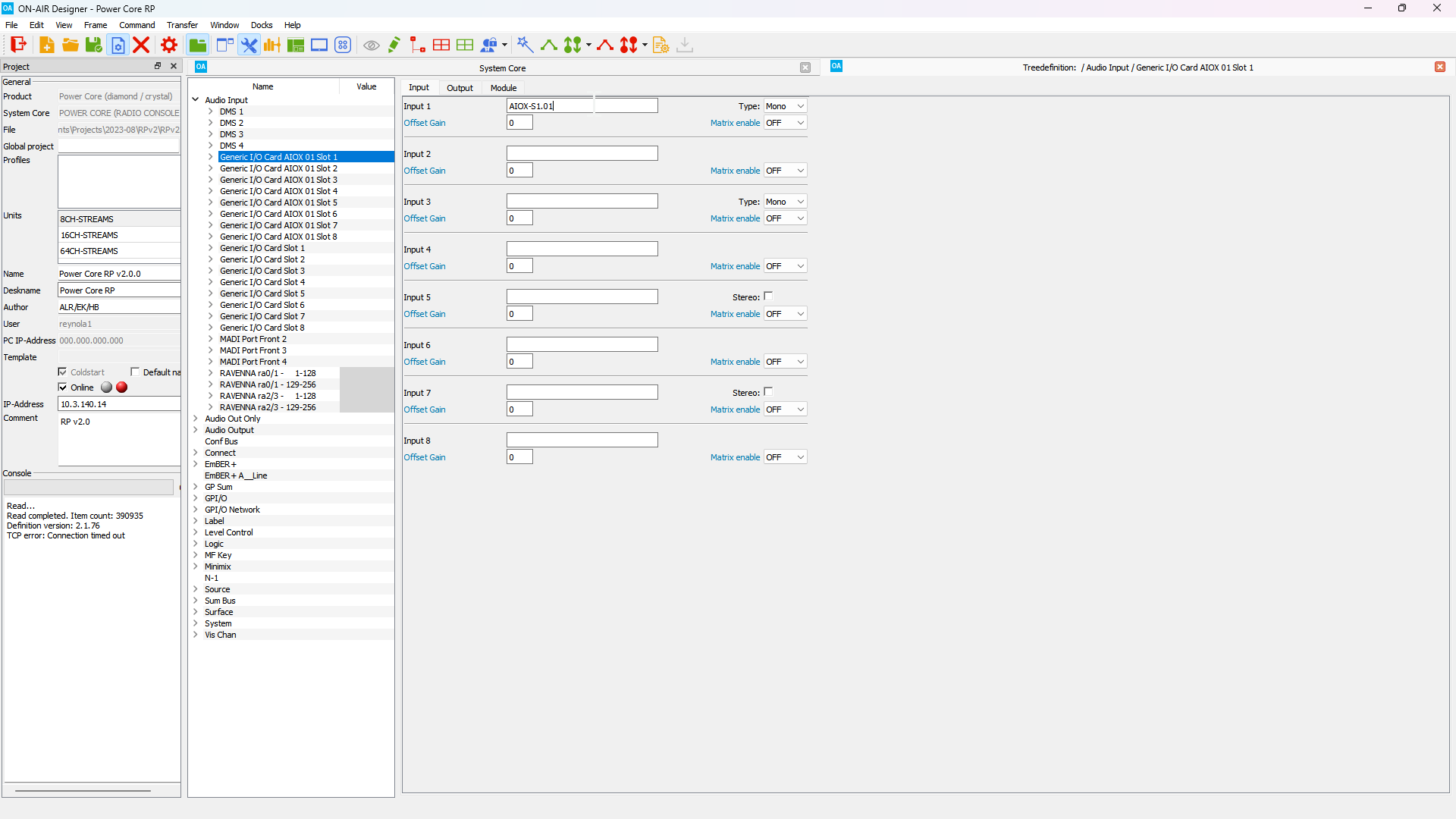
Lawo recommends using AIOX signal names in the form AIOX-xxSy.zz, where xx is the AIOX number (1-20), y is the slot number (1-8), and zz is the zero padded channel number (01-08).
8. Once the Input signals have been labeled, they must be Matrix Enabled so that they can be used in the routing system. Click the Matrix enable drop down box and select ON.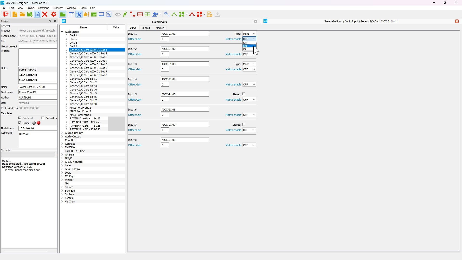
9. Click on the Output tab and repeat the process for the output signals. 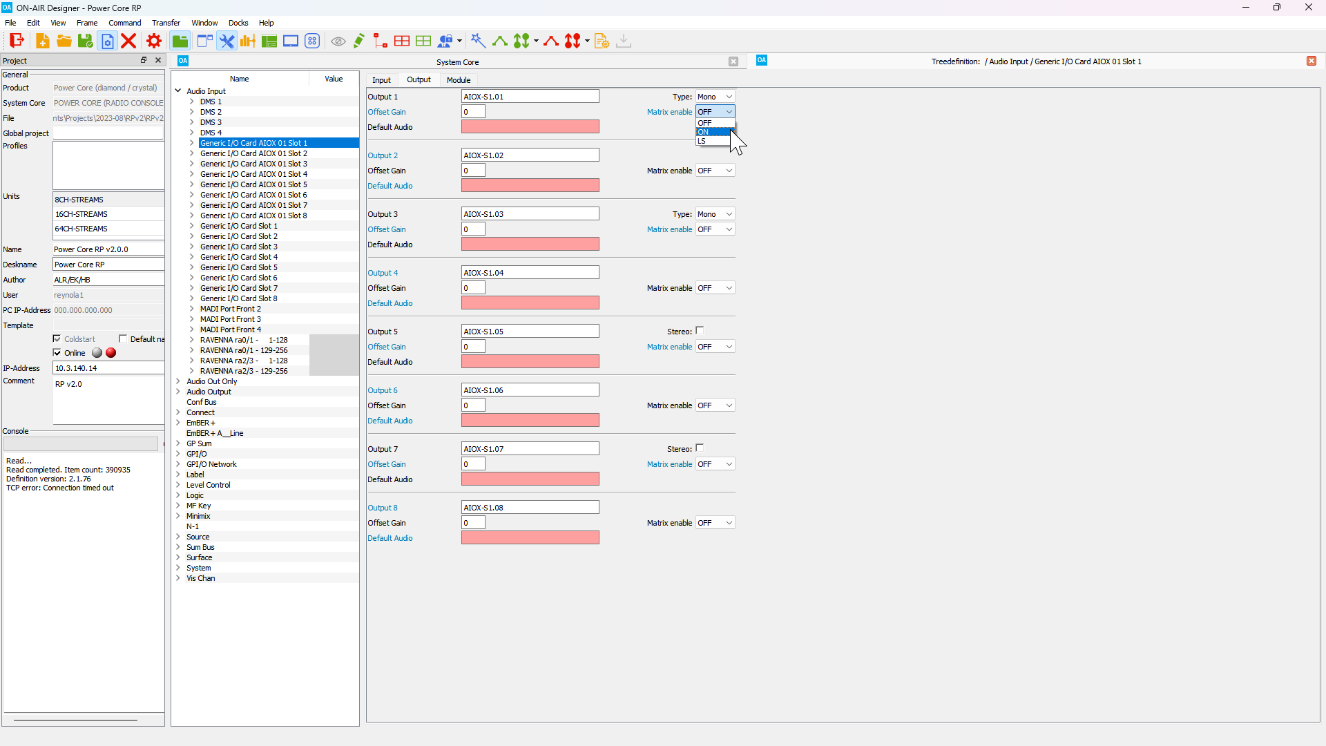
10. Repeat Steps 7-9 for each of the new Generic I/O cards.
Remember that IO signal names will only be reflected in the VisTool RP GUI. HOME will automatically generate signal labels for physical IO.
11. Save the updated configuration and follow the steps to load the updated configuration.
Adjusting the Talkback Input Level Detection Thresholds
Each of the Talkback inputs can detect when level is present on the input. This is used to trigger the insertion of the Talkback input into any selected Aux Buses, and also dim the program content of the selected Aux Bus.
The level at which a signal is considered to have audio present can be configured in ON-AIR Designer, as well as well as the length of time for which audio has to be present or silent to trigger the insertion.
1. Navigate to the Tree Definition window in ON-AIR Designer (Command > Treedefinition in the top menu bar) and open the Audio Input folder. Select the DMS 1 folder to open the DMS 1 signal configuration window. 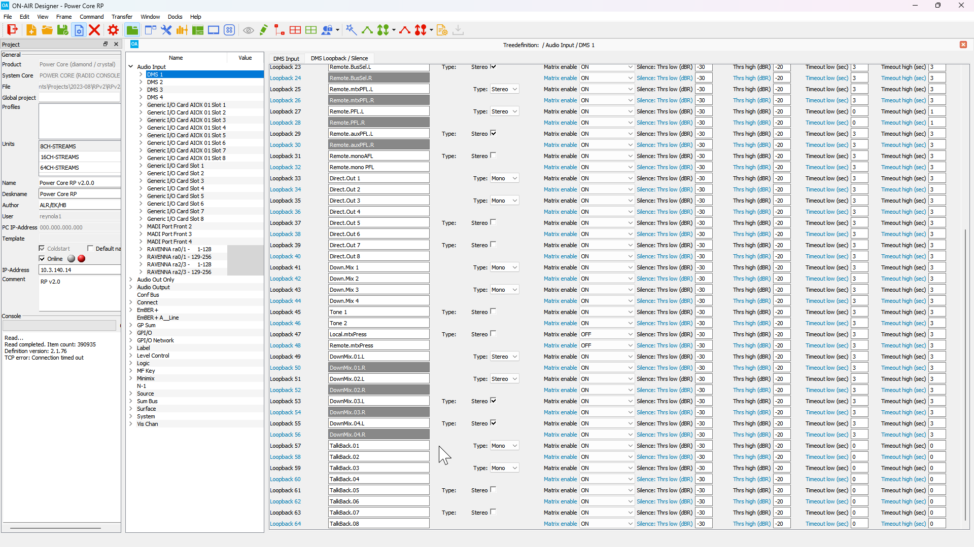
2. The Talkback inputs are configured to use Loopbacks 57-64. To the right of each Talkback loopback signal are the Silence: Thrs low (dBr) and Thrs high (dBr) property boxes. The Thrs low property sets the value at which the signal will be considered silent. The Thrs high property sets the value at which the signal will be considered present. The default value for silence is -30dBr and the default value for level present is -20dBr.
To convert from relative decibels (dBr) to decibels Full Scale (dBFS), add the Relative System Level to the dBr value, then add 18dB. For example, with a Relative System Level of -38:
-30dBr = -30dBr + -38dB +18dB = -50dBFS
For more information about the relative decibels see Power Core RP v2 - System Reference Levels.
3. The Timeout Low and Timeout High values can be adjusted to govern the behavior of the talkback insertion. In order for Talkback to be inserted, the signal level must exceed the value defined in the Threshold High property for the time defined in the Timeout High property. The Talkback input will remain active until the signal level is below the value defined in the Threshold Low property for the time defined in the Timeout Low property.
4. Co-Mixer Inputs 1-8 can also be used in the Talkback system. These signals are located in the DMS 2 folder and use Loopbacks 33-40.
Configuring RAVENNA stream receiver time offsets
By default, the Power Core RP v2 will use the dynamic stream tuning process described in Power Core RP v2 - Stream Tuning. However, it is also possible to configure either a fixed time offset per receiver, or maximum time offset value for each device group.
1. To configure a fixed time offset for a specific receiver navigate to the Tree Definition window in ON-AIR Designer (Command > Treedefinition in the top menu bar) and select the RAVENNA stream group that contains the receiver you wish to edit.
2. Each stream receiver has a Fixed Time Offset property. The default value is 0, which means the receiver will use the dynamic tuning process. To set a fixed time offset enter the desired time offset in samples.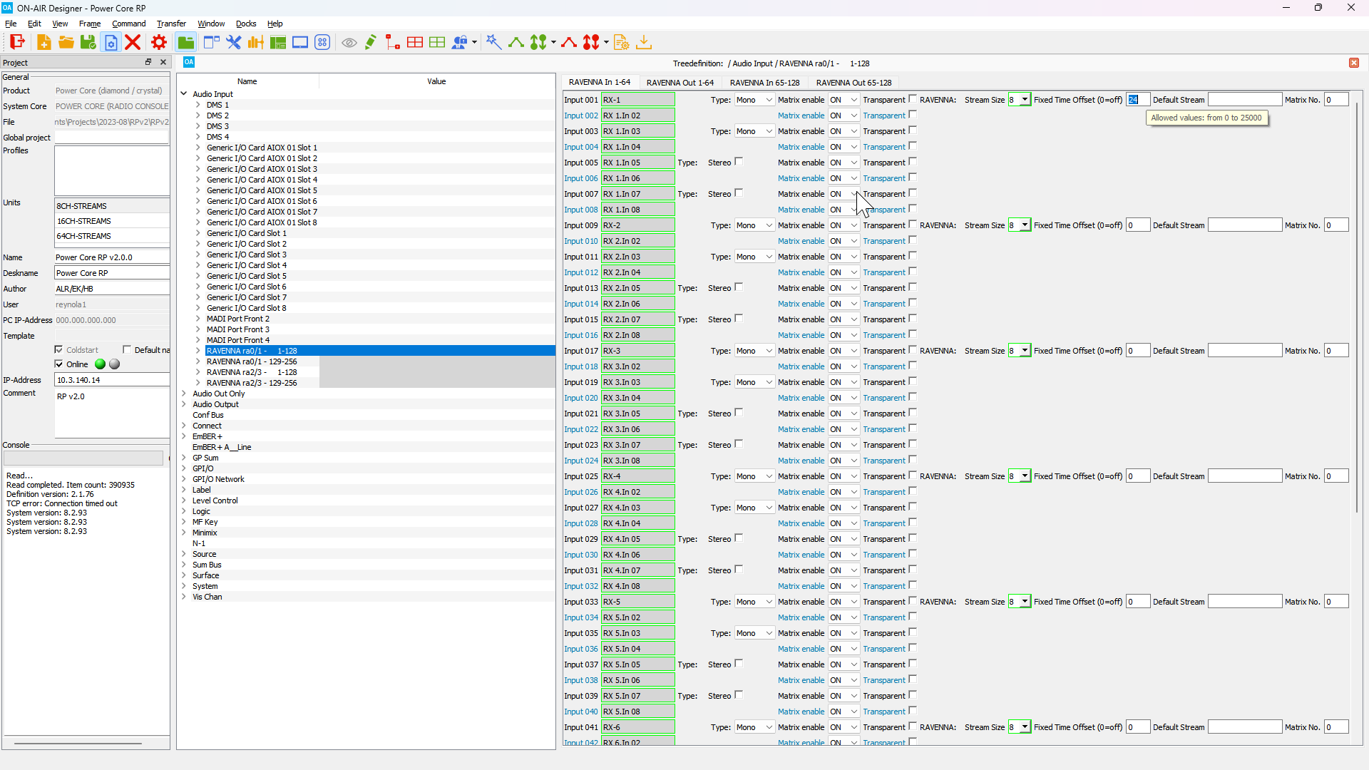
1. To configure a maximum time offset navigate to the Tree Definition window in ON-AIR Designer (Command > Treedefinition in the top menu bar). Expand the System folder, select the Definition sub-folder and then select the Ravenna tab.
2. Scroll down to the Stream Settings section of the Ravenna tab. Set the RX Time-Offset Max property in samples for the ra0/1 device group.
For a Revision 3 Power Core it is also possible to define separate maximum time offsets for the ra0/1 and ra2/3 device groups–this is useful when one device group is used on a WAN link.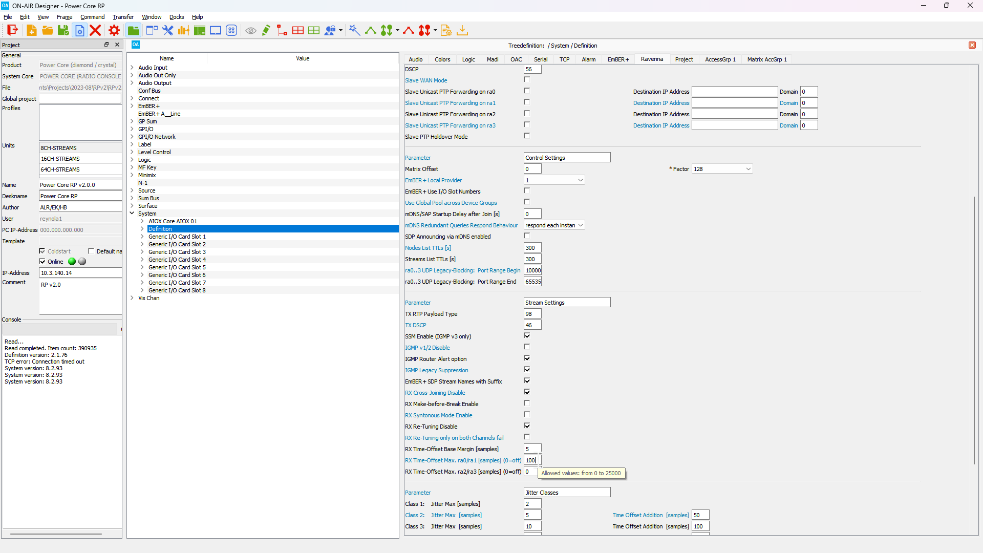
Configuring RAVENNA stream sender parameters
The RAVENNA stream senders in Power Core RP v2 can be configured to use specific multicast addresses, stream names, codecs, UDP ports or samples per frame.
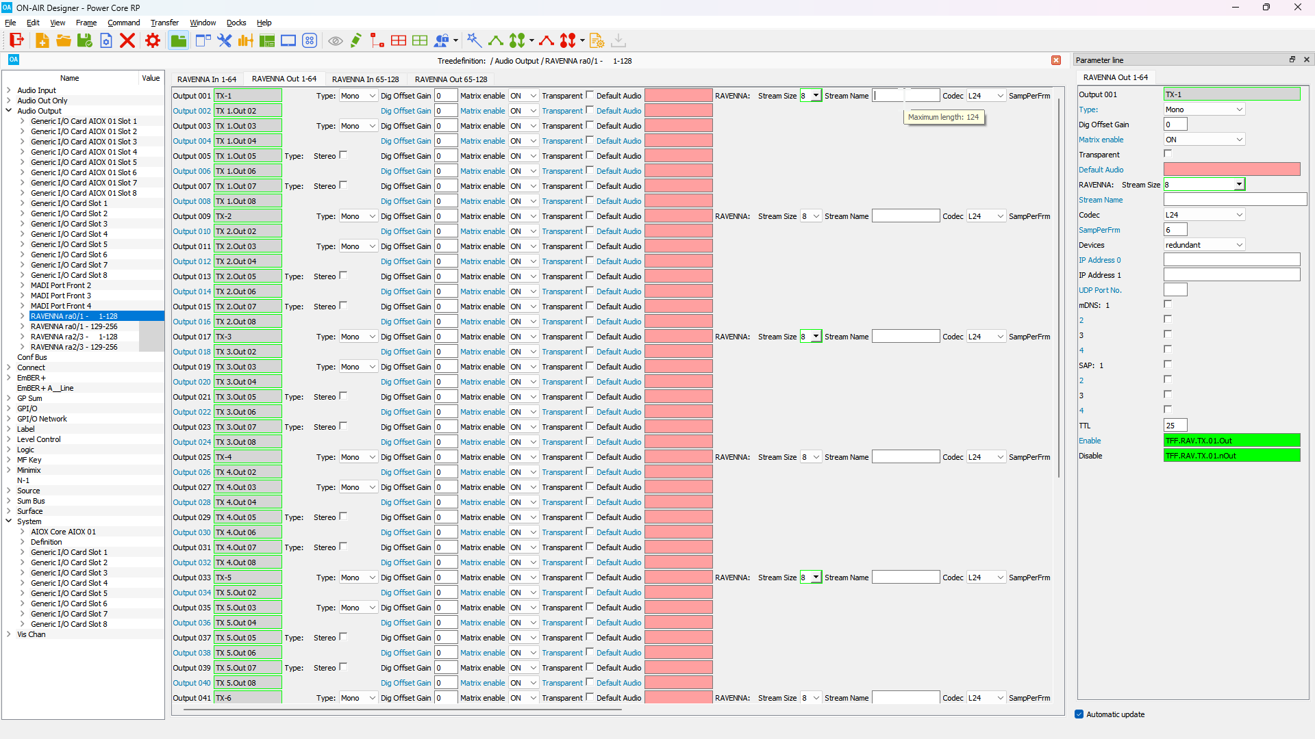
1. To configure a fixed time offset for a specific receiver navigate to the Tree Definition window in ON-AIR Designer (Command > Treedefinition in the top menu bar) and select the RAVENNA stream group that contains the sender you wish to edit.
2. For each sender editing the following properties is supported:
- Stream Name - This is the descriptive name of the stream that will be used to identify the stream. This name will also be used for mDNS and SAP advertisements (if enabled).
- Codec - 16 bit PCM (L16), 24 bit PCM (L24), 32 bit PCM (L32), and AM824 codecs are supported.
- SampPerFrm - The number of samples per frame. Values from 1 to 64 are supported, but make sure to not select a value that will cause the frame payload to be larger than 1400 bytes.
- Devices - Select the device(s) to use when sending the stream.
- IP Address 0|1 - Set a multicast IP address for the stream or the destination unicast IP address.
- UDP Port No. - Set the UDP port number to be used by the RTP stream.
- mDNS 1-4 - Enable mDNS stream advertisements on mDNS rings 1 - 4. mDNS rings are defined in
System>Definition>Stream Announcement. - SAP 1-4 - Enable SAP stream advertisements on SAP rings 1 - 4. SAP rings are defined in
System>Definition>Stream Announcement. - TTL - Define how many hops the stream supports in the network path.
Changing the stream widths for RAVENNA senders or receivers is not supported! Check with your Lawo Project Engineer before changing any settings not documented in this guide.