mc²36 - Fader Strip Controls
The fader strips provide dedicated mixing controls for the channels assigned to the current bank/layer.
All faders and rotary controls are touch-sensitive, and are clearly labelled by the panel's displays. Any fader strip can control any type of channel and supports six banks, each with two layers. This allows you to control inputs and masters from any fader position, and handle lots of signals from very few physical faders.
Controls Overview
Each fader strip is divided into the areas described below.
There are three possible variants: the single- or dual-fader channel bays (in a 32F or 48F console), and the main fader strips (in all console frames). Note that the lower controls (4 to 11) are identical for all variants. The upper controls (1 to 3) differ as follows:
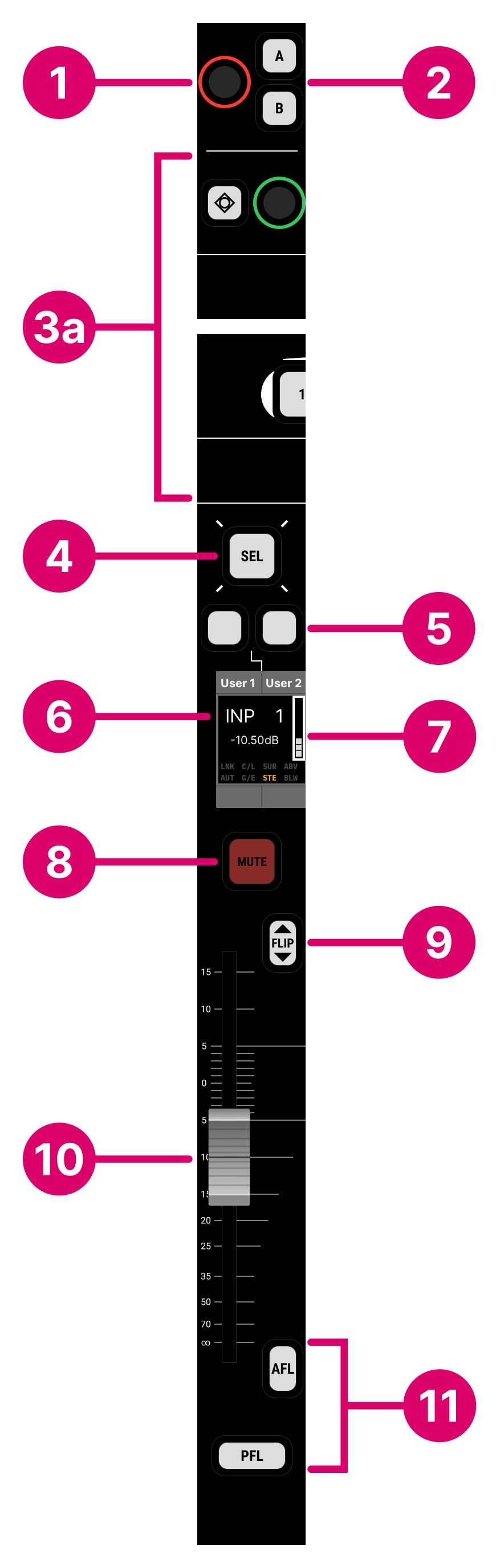
- In a 32-fader console, the channel bay is fitted with the standard fader panel, with input gain, A/B switching and an assignable Free Control (FC).
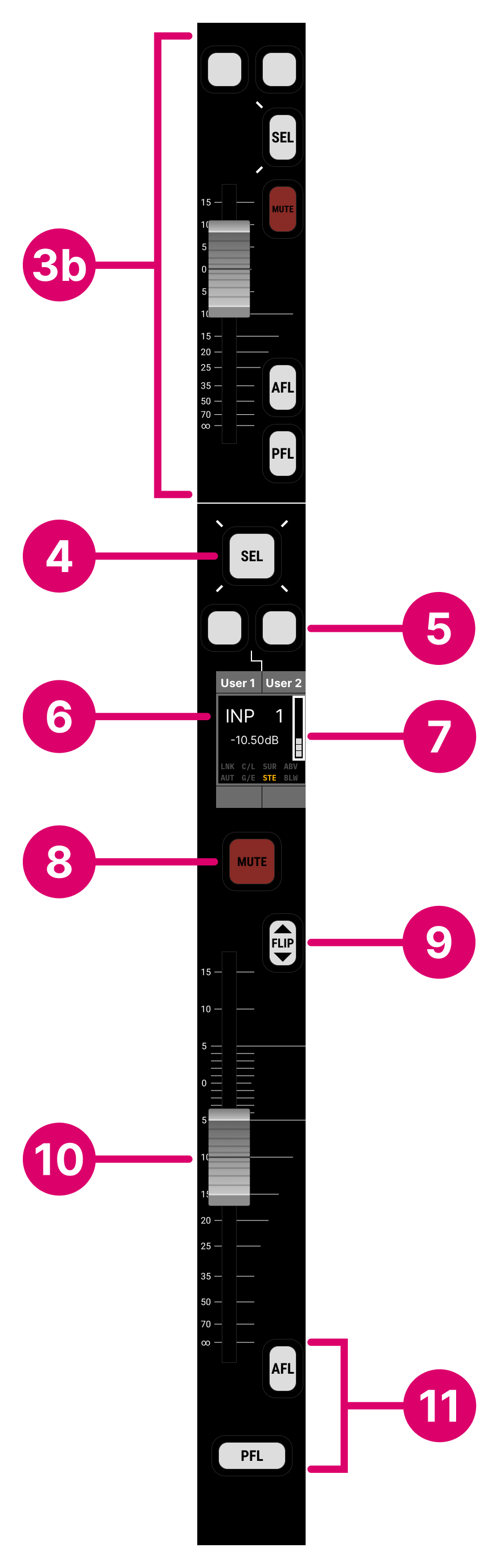
- In a 48-fader console, the channel bay is fitted with a dual-fader panel. This provides a second (upper) short-scale fader at the expense of the A/B switching and rotary controls.
- In a 16-fader console, there is no channel bay and so the console supports main fader strips only (with no upper controls).
Single-fader Strip |
Dual-fader Strip |
Main Fader Strip |

Operation
The main points of operation are as follows.
In a single-fader channel bay:
- The upper rotary control (1) always adjusts source gain.
- The other rotary control (3) is an assignable Free Control. This can be assigned or paged to any channel parameter: EQ Gain, Compressor Threshold, Aux send, etc.
In a dual-fader channel bay:
- The upper fader (3b) always controls the alternate layer.
On all fader strips:
- Press SEL (4) to select the channel. For example, to adjust its parameters centrally or perform an access/assign operation.
- The fader user buttons (5) are programmable and can trigger channel operations: e.g. Conference on/off, Talkback, Snapshot Isolate, EQ on/off, etc.
- The label (6) identifies the channel. If there is signal present at the channel input, then this is shown on the input meter (7).
- Press FLIP (9) to switch the fader strip to the alternate layer. On a dual-fader panel, this reverses the upper and lower fader assignments.
- Use the fader (10) and/or MUTE (8) to adjust the channel level.
- Press AFL or PFL (11) to monitor a channel in isolation.
The rest of this topic describes the controls in more detail.
1. Input Gain (32F only)
On a single-fader channel strip, the upper rotary control always adjusts source gain (either mic/line or INMIX gain depending on the source type). The amount of GAIN is shown at the bottom of the Channel Display.
Note that the same parameters can be adjusted centrally from either the Central Control Section or Main Display. This method must be used when working with dual-fader channel or main fader strips. See mc²36 - Channel Parameters.
2. A/B Input Switching (32F only)
On a single-fader channel strip, the A and B buttons can be used on input channels to switch between a main and backup source. For each channel, the sources must be connected to the A and B inputs using the Signal List display. If nothing has been assigned to an input, then the corresponding button cannot be selected.
Note that each channel supports a third (C) input. This, and the A/B buttons, can be switched from the input section on the Central GUI's Main Display or programmed onto a user button. This method must be used when working with dual-fader channel or main fader strips.
3a. Free Control (32F only)
On a single-fader channel strip, there is one assignable Free Control (FC).
The controls are color-coded, making it easy to distinguish between the parameter types: EQ (blue), dynamics (magenta), aux sends (green), etc. The current function and value are shown on the Channel Display.
The default assignments can be changed using the COPY/RESET AUDIO panel (as described here). At any time, you can override the default assignments by recalling an FC PRESET. These change the function of all Free Controls within the channel bay. When you deselect the FC PRESET, the controls return to their default assignments.
Each Free Control includes a touch-sensitive rotary control and push-button. The button function depends on the assigned parameter (e.g. Aux send on/off). The rotary control operates in the same way as other rotary controls on the surface:
- Turn for fine adjustment OR push down and turn for coarse adjustment*.
- Tap down twice in quick succession to reset the parameter value.
*The fine/course tuning behaviour can be reversed, globally, using the "Console → Potentiometer → Invert Pot Fine/Course Tuning" option (in the System Settings display).
FC PRESETS, BANK/LAYER & ISO BAY
Beneath the Free Controls on a single-fader channel bay is a horizontal strip of buttons that provide FC PRESET control, BANK/LAYER switching (locally for the bay) and ISO BAY.
Note that the same local BANK/LAYER and ISO BAY functions can be found at the top of the Channel Display.
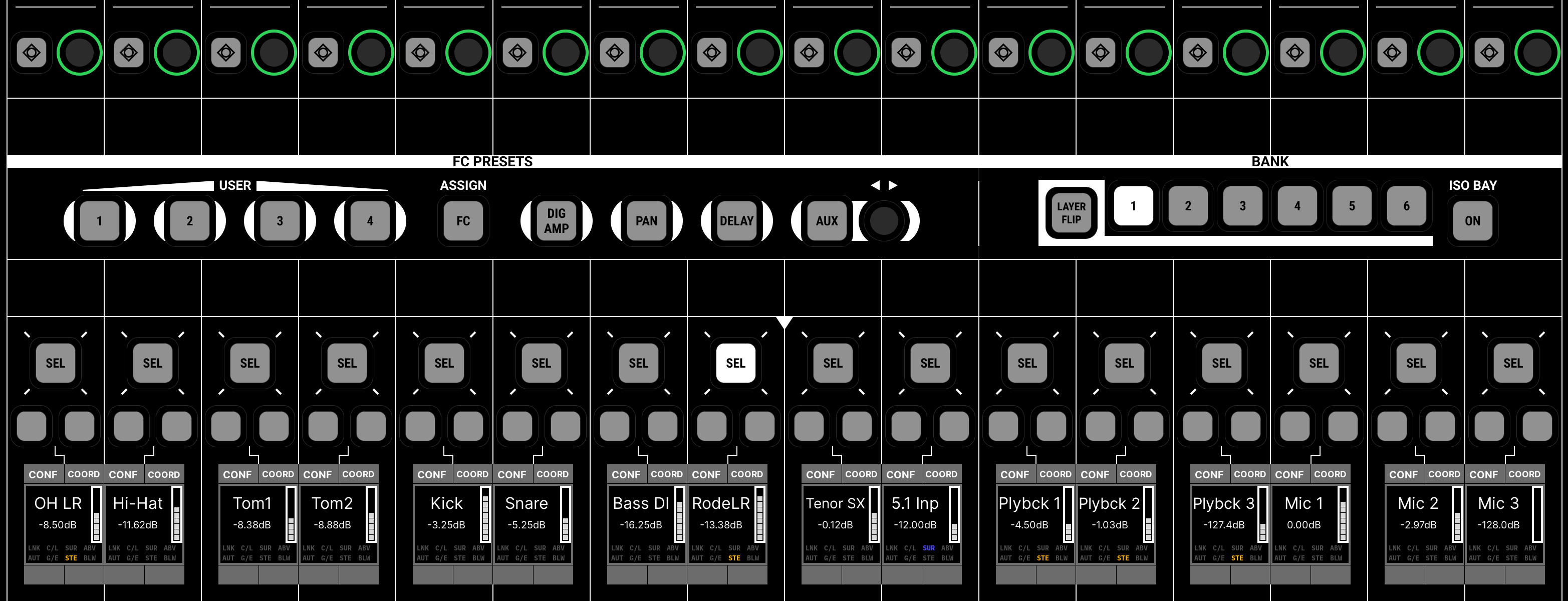
The FC PRESETs can be used to change the function of all Free Controls within the channel bay. For example, press DIG AMP to access the digital amplifier; PAN for panning; DELAY for delay and AUX for aux sends. If more than one parameter is available, then turn the rotary control to scroll through the available pages (e.g. Aux 1, Aux 2, Aux 3 and so on). When you deselect the FC PRESET, the controls return to their default assignments.
To access a different channel parameter, you can use the four user-defined FC PRESETS as follows:
- Start by assigning the required parameter to a fader strip's Free Control and press SEL (to select the channel).
- Then, press and hold a USER preset button (1 to 4) until it flashes - this stores the selected channel's Free Control assignment.
- For the recall, press the same numbered button - the stored Free Control assignment is recalled to all 16 fader strips within the channel bay.
The ASSIGN FC button is used, in conjunction with the COPY/RESET AUDIO panel, to edit the default Free Control assignments. See mc²36 - Free Control Assignment.
- Press a button to change the bank or flip layer of all 16 fader strips.
- If ISO BAY is off, then the bank and layer is reset by the global BANK/LAYER buttons (in the centre section).
- If ISO BAY is on, then the bay is unaffected by the global BANK/LAYER switching.
ISO BAY ON isolates the channel bay so that it is unaffected by the global BANK and LAYER switching. See mc²36 - Isolated Bay.
3b. Second Fader (48F only)
If the channel bay is fitted with the dual-fader panel, then the Input Gain, A/B switching and Free Control are replaced by a second (upper) short-scale fader. The upper fader always controls the alternate layer. Press FLIP (beside the lower fader) to reverse the assignments.
The upper fader comes with two user buttons, a fader strip SEL button, MUTE plus AFL and PFL monitoring. These operate in an identical manner to the first (lower) fader described below.
If you need to adjust other channel parameters, then press a fader SEL button and use the parameter control areas in the Central Control Section.
In this instance, there are no FC PRESETS (as there are no fader strip Free Controls) and the local BANK/LAYER switching and ISO Bay on/off can be accessed from the top of the Channel Display.
4. SEL (Fader Select)
The fader SEL button can be used to select a channel, otherwise known as placing a channel "in access". Once selected, you can adjust the channel's parameters centrally (from the Central Control Section or Main Display), or perform an access/assign operation such as moving the channel to a different fader strip.
On a VCA or bus master, you can press and hold the SEL button to activate Reveal In Place. The slave channels appear beside the master so that you can quickly adjust their parameters.
5. Fader User Buttons
The two fader user buttons can perform "channel-related" custom functions such as mix minus control (CORD and CONF), snapshot isolate (SNAP ISO) and talkback (TALK).
Four pages of functions are available, switched from the centre section's FADER USER BUTTON panel. The functions are clearly labelled by the display.
All user buttons are programmed from the Custom Functions display and are stored at a system level. This means that any changes will affect all users.
6. Label
The fader strip label display can show either a text label or image to identify the channel.
The "labels" are switched globally from the centre section LABEL buttons. From here, you can choose which text labels are in view, and whether LiveView images are enabled.
- CHANNEL NAME = the system name of the channel (e.g. INP 1). This is system-defined and cannot be edited.
- USER LABEL = the user label given to the channel (e.g. Guest).
- INHERIT SOURCE = the user label given to the source connected to the channel (e.g. Mic 1).
If the IMAGE button is enabled, then the 'Signal Thumbnails' assigned to the channel or source are displayed instead of the text labels.
The background color of the display can also be used to quickly identify the channel.
7. Input Meter & Status Indicators
The fader strip label display includes a signal present meter. The pickup point is always at the channel input. This allows you to check that signal is present before opening a fader.
Below the label and meter are several channel status indicators. When lit, the indicators show the following information:
- LNK = processing modules within the channel are linked as part of a link group
- AUT = automation is enabled (for the fader).
- C/L = either the compressor or limiter is active.
- G/E = either the gate or expander is active.
- SUR = the channel format is surround.
- STE = the channel format is stereo.
- ABV or BLW = when using timecode automation, indicates that the level stored in the play pass is above or below the current fader level.
8. Channel Mute
Press the MUTE button to mute the channel.
The mute position can be set globally for all channels to either after fader or after the input mixer. In addition, you can disable the MUTE button operation, globally, to prevent accidental operation during a live show. Both options are defined in the System Settings display: select "Global → Status" and then look for the "Channel Mute" and "Mute" options.
9. Layer FLIP
Press FLIP to switch the fader strip to the alternate layer. On a dual-fader panel, this reverses the upper and lower fader assignments.
Layers can also be switched locally within the bay or globally from the centre section.
10. Fader
By default, the fader adjusts the channel level from -∞ to +15dB.
The faders can be switched, globally, from the FADER CONTROL panel (to adjust a different level parameter such as an aux send or the direct out).
All faders are motorised and touch-sensitive. The fader motors can be turned off (for non-moving VCA slaves). There is also a notch that can be set to any position, and an overpress function that is triggered when you pull back on the fader (e.g. for a fader start or backstop PFL). These options are defined in the System Settings display (under "Fader/Joystick → Fader").
11. AFL & PFL
Press AFL to listen to the post-fade channel signal. Press PFL to listen to the pre-fade channel signal. The listen buses can be switched to different monitor outputs using the Control Room Monitor (CRM) options on the Central GUI side panel.