mc²36 - Master Controls
The centre section provides master controls and navigation for the Central GUI.
This topic describes each of the control areas, from top to bottom and left to right.

MONITORING
The CRM 1 and CRM 2 rotary controls adjust the level of the control room monitoring outputs. The physical controls work in conjunction with the Central GUI (as described later).
PRODUCTION
The UPDATE button saves the current console settings into the active production. Note that the button overwrites (updates) the active production. If new snapshots have been saved, then the button flashes as a reminder to save.
To the left of the button is a USB port. This can be used to connect a memory stick to import or export productions and other user data.
TALKBACK
This area provides a central user button (ideal for global talkback). The user button is programmed from the Custom Functions display. Note that it can be assigned to any central user button function, not just talkback switching.
A talkback mic can be connected to the female XLR connector (beside the user button). This is wired directly to the TB connector on the console's rear panel. From here, it can be connected to the console's local MIC IN 16 (on the rear panel). The input must then be defined as the talkback source in the relevant Custom Functions.
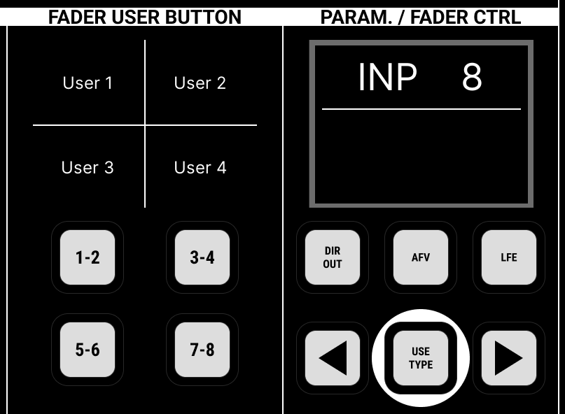
FADER USER BUTTON
This panel switches the fader strip user buttons, globally, between their four pages of functions. Press the 1-2, 3-4, 5-6 or 7-8 buttons to select a page. The current functions are shown on the FADER USER BUTTON panel (above the page buttons).
PARAM. / FADER CTRL
The display on this panel shows the selected parameter during operations such as a copy or reset.
The FADER CONTROL buttons can be used to temporarily assign another level parameter onto the console's faders. For example, press AUX SENDS to assign an aux send - the fader labels across the console show the parameter name (e.g. AUX 1), and flash to warn you that you are now controlling something other than the main channel level! You can now use the arrow buttons to scroll through the available aux sends.
Alternatively, touch an aux send control (on the Central Control Section) and then press USE TYPE - this switches the faders directly to say Aux Send 28 without scrolling.
The following level parameters can be controlled in this manner: AUX SENDS (send levels); DIG AMP (digital amplifier gain); INSERT SEND (insert send level); DIR OUT (direct output level); AFV (audio follow video On level); LFE (Subwoofer level).
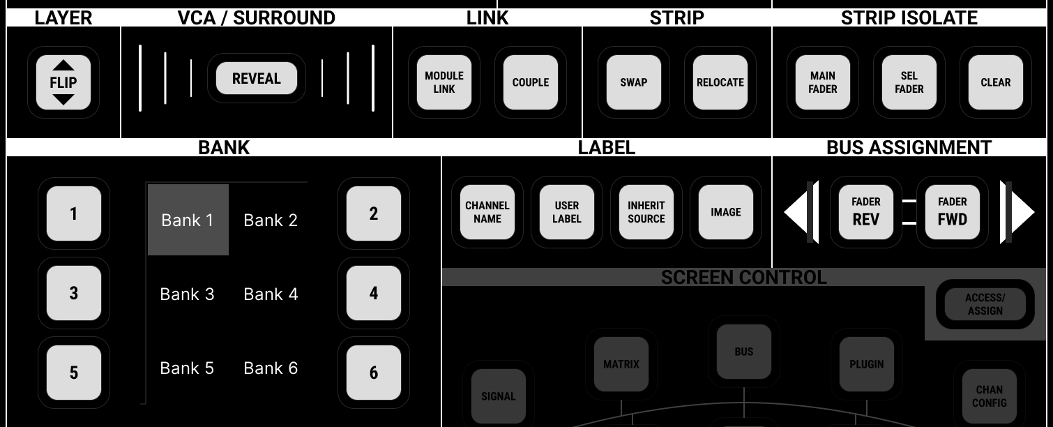
LAYER & BANK Switching
The BANK 1 to 6 buttons switch the fader strips, globally, between banks. One button is always lit; this is the active bank. Six banks are available. The banks can be labelled from the Central GUI side panel (using the Access/Assign 2 page).
Within each bank, you can press LAYER FLIP to invert the layers.
The bank/layer selections affect all fader strips across the console, except for those in an isolated bay (ISO BAY on) or with an ISO state active (under STRIP ISOLATE).
VCA / SURROUND
The REVEAL button reveals the channels assigned to a VCA or bus master so that you can apply offsets. The function can be used to reveal a VCA, Surround VCA, Group, Aux or Sum master.
First, select the VCA or bus master by pressing its fader SEL button. Then press REVEAL - the channels assigned to the VCA or bus appear in the global reveal position (defined using the "Console → Reveal" options in the System Settings display).
LINK
The MODULE LINK button is used to create link groups. If you wish to apply a link group offset, then the LINK OFFSET option can be found on the Central GUI side panel (Access/Assign 3 page).
The COUPLE button can be used to create a couple.
STRIP
The SWAP and RELOCATE buttons can be used to change which channels are assigned to the fader strips (via a swap or relocate).
The other strip assignment functions are available from the Central GUI side panel (using the Access/Assign 1 & 2 pages). For more information, see mc²36 - Strip Assignment.
STRIP ISOLATE
The STRIP ISOLATE options can be used to isolate fader strips from bank switching: either all main fader strips (in the centre section), or specific fader strips (in any bay).
- Turn on MAIN FADER to isolate all main fader strips.
- Or, press SEL FADER and then select the strips you wish to isolate (by pressing their fader SEL buttons: red = selected).
- To clear all isolations, press CLEAR.
LABEL
The LABEL buttons change what is shown in the "label" fields on the fader strips and GUI. From here, you can choose which text labels are in view, and whether LiveView images are enabled.
- CHANNEL NAME = the system name of the channel (e.g. INP 1). This is system-defined and cannot be edited.
- USER LABEL = the user label given to the channel (e.g. Guest).
- INHERIT SOURCE = the user label given to the source connected to the channel (e.g. Mic 1).
If the IMAGE button is enabled, then the 'Signal Thumbnails' assigned to the channel or source are displayed instead of the text labels.
For more information, see mc²36 - User Labels.
BUS ASSIGNMENT
The FADER REVERSE and FADER FORWARD buttons are used to make bus assignments either to or from the channel in access. For example, to assign several input channels to a sum:
- Select the SUM, either by pressing its fader SEL button or using the Access/Assign panel.
- Then press FADER REV - the fader SEL buttons across the console show the current assignments: red = assigned; flashing green = unassigned.
- Now press the fader SEL buttons to change the assignments.
The same method can be used to assign channels to a group, aux or VCA. FADER FWD works in a similar manner but this time select the channel you wish to assign from (e.g. an INP channel).
CENTRAL USER BUTTON
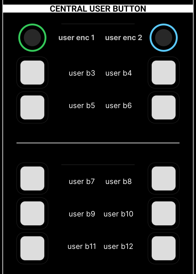
The user buttons can be used for master functions such as enabling the second metering row on the Channel Displays; start/stop/reset for integrated loudness measurements; copy and paste for copying levels to auxes, etc.
The rotary encoders can be assigned to master levels such as the headphone output levels.
All functions are programmed from the Custom Functions display and are stored at a system level. This means that any changes will affect all users.
SCREEN CONTROL
The SCREEN CONTROL panel works in conjunction with the Central GUI. It can be used for page selection and navigation.
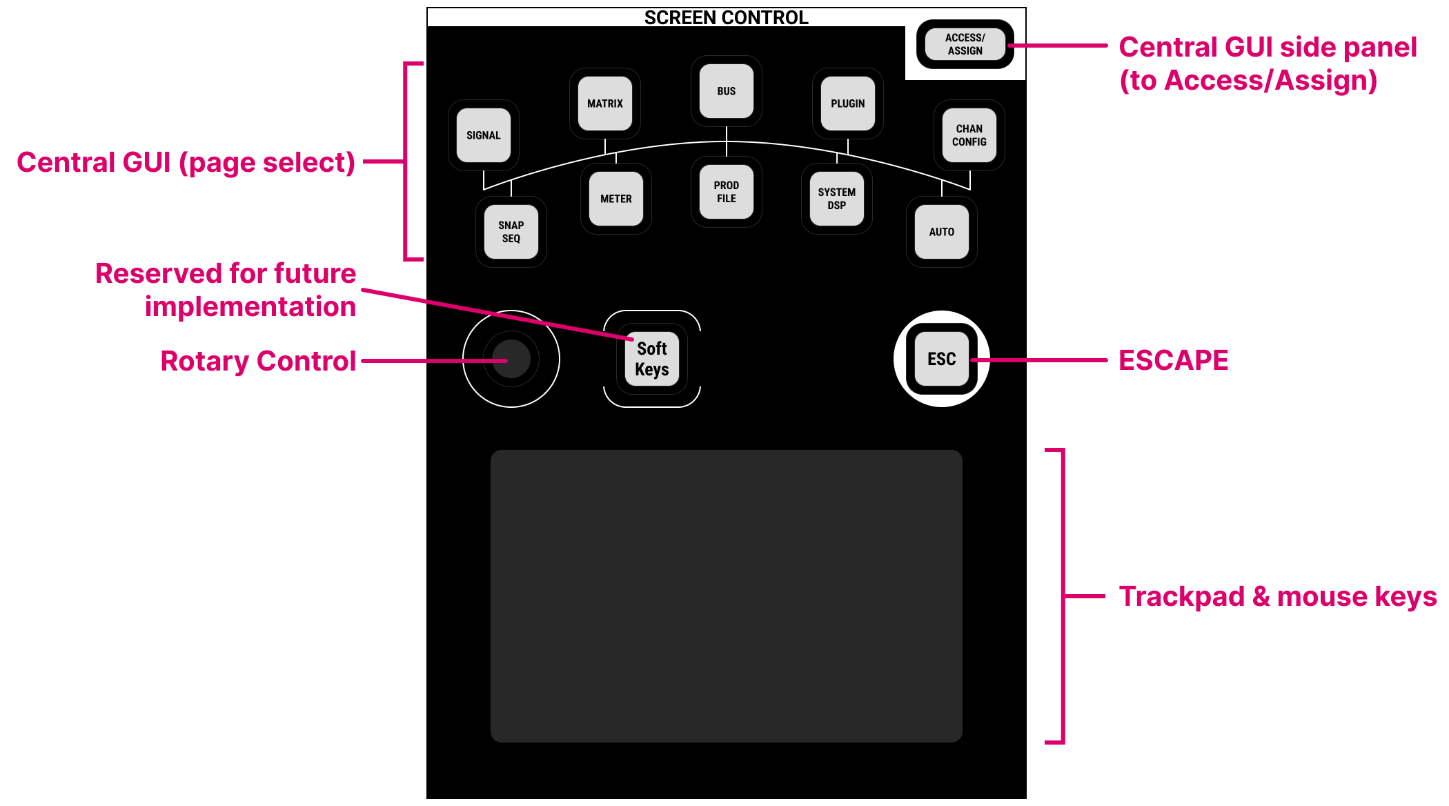
The following operations are possible:
- ACCESS/ASSIGN - press this button to switch the Central GUI side panel between MONITORING and ACCESS/ASSIGN. The side panel pages are described here.
- Display Selection - press a button (e.g. BUS) to change the Central GUI display. In most cases, the button provides access more than one page, so keep pressing to cycle through all available pages.
- Soft Keys - in the current release, this button has no function. It is reserved for future implementation.
- Rotary Control - this control can be used to adjust a value (once a parameter field is selected) or scroll up and down (when working in a list).
- ESC Key - press escape to cancel out of an operation.
- Trackpad & Mouse Keys - as an alternative to the touch-screen, you can use the trackpad and mouse keys to make selections. The mouse keys are located at the bottom of the trackpad: left-click to make a selection or enable/disable on-screen buttons; right-click to view the context menu options.
Note that, on the mc236, there are no soft keys on the SCREEN CONTROL panel. Instead, you can access these functions from the Central GUI touch-screen, either as a dedicated button or context menu (right-click) option.
The operation of the Central GUI is described in the next topic.