mc²36 - Control Room Monitoring
CRM 1 supports all possible surround formats, while CRM 2 is stereo. The connections are usually made using the local I/O so that the loudspeakers can connect to the console rear panel.
There are also two stereo headphone outputs: HP 1 and HP 2. The phones sockets can be found on the front buffer. By default, the two HP outputs follow the CRM source selectors with independent level control.
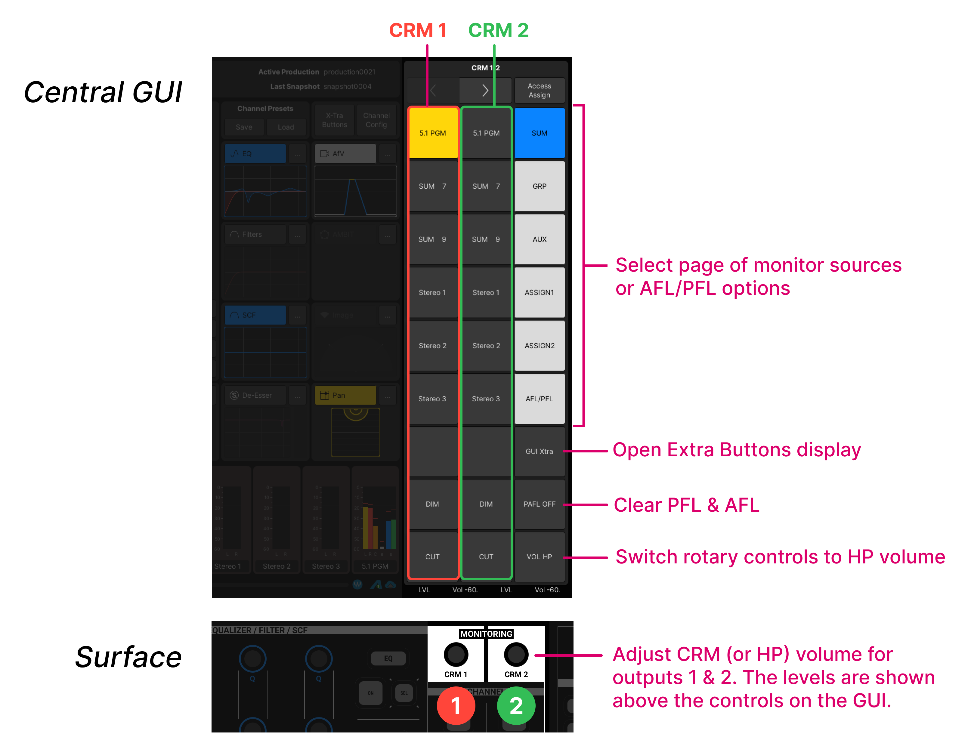
The CRM and HP levels are adjusted from the surface (using the MONITORING rotary controls below the Central GUI). All other options are adjusted from the touch-screen (using the Central GUI side panel).
The level controls for CRM 1 and CRM 2 are located on the surface (below the Central GUI). All other controls, including source selection, are handled from the touch-screen (via the Central GUI side panel).
The instructions below describe the default monitoring configuration. The operation may vary if the configuration is customized.
- Make sure that the Central GUI side panel is switched to monitoring mode by turning off the Access Assign button.
- Use the touch-screen arrow buttons to open the first page (CRM 1/2). Here you will find three columns of controls for CRM 1, CRM 2 and page selection/other functions.

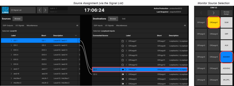
Monitor Source Selection
- Use the right-hand column to select a page of sources: SUM, AUX, GRP, etc.
- Select an option in the left column to assign a source to CRM 1.
- Select an option in the middle column to assign a source to CRM 2.
You can choose sources from different pages to assign say the 5.1 PGM output to CRM 1 and a stereo group to CRM 2.
The first three source pages provide "hard-wired" access to sums, auxes and groups, while pages 4 and 5 are reserved for assignable sources. The sixth page (AFL/PFL) provides access to the AFL/PFL monitoring options.
In the default configuration, headphone 1 follows the CRM 1 source selector and headphone 2 follows CRM 2.
Volume, CUT and DIM
- Turn the rotary controls to adjust the volume of each monitor output.
- Press down the display controls to DIM, CUT or open the volume
Alternatively, you can use the dedicated DIM and CUT buttons on the touch-screen side panel. The amount of dim defaults to 20dB but this can be adjusted using the Set function (described later).
The same rotary controls adjust the volume of the two headphone outputs when the VOL HP touch-screen button is active.
The current function and levels are always shown at the bottom of the touch-screen display: either LVL Vol -xxdB for loudspeaker control or LVL HP -xxdB for headphones.
Assignable Monitor Sources
The CRM 1/2 monitoring side panel provides two pages of programmable source selection buttons: ASSIGN 1 and ASSIGN 2. The buttons can be used to monitor any input by assigning sources to the button destinations from the Signal List display. 
In total there are 24 programmable buttons: 12 for CRM 1 and 12 for CRM 2. They are arranged over the two pages as follows.
ASSIGN 1
- CR1asgn1 to CR1asgn6 - 6 x surround sources for CRM 1.
- CR2asgn1 to CR2asgn6 - 6 x stereo sources for CRM 2.
ASSIGN 2
- CR1asgn7 to CR1asgn12 - 6 x surround sources for CRM 1.
- CR2asgn7 to CR2asgn12 - 6 x stereo sources for CRM 2.
To assign a source to a button:
- Open the Signal List display in the usual manner.
- Under Destinations, select Miscellaneous -> Loopback Inputs.
- Scroll down the list until you see the destination you wish to program (e.g. CR2asgn1).
- Then select a source (e.g. CD 1) and make the connection in the usual manner.
To monitor the source, press the corresponding button on the monitoring side panel (e.g. CR2asgn1). In our example, you should hear CD 1 on the CRM 2 output.
AFL & PFL
- The behaviour of the buttons is determined by the AFL, PFL and SIP options in the System Settings display.
- The A/PFL buses can be split to provide independent monitoring from isolated bays.
- In this instance, AFL and PFL in an isolated bay feeds AFL2 and PFL2.
- The Enable PFL2/AFL2 option must be enabled (under "Listen" in the DSP Configuration display).
- AFL1 supports surround; while AFL2, PFL1 and PFL2 are stereo.
- The format of the AFL1 bus is determined by the AFL1 Surround Format option (under "Listen" in the DSP Configuration display).
- The A/PFL buses can be switched to either or both monitor outputs (using the AFL/PFL page in the monitoring options).
- The A/PFL buses can also be connected to any available I/O. For example, to connect an external PFL speaker.
- The listen bus outputs can be found in the DSP Outputs → AFL & PFL Outputs directory (on the Sources side of the Signal List display).
To set up the AFL and PFL monitoring:
1. Select the AFL/PFL page on the monitoring side panel.

2. Use the first two columns to select the options for CRM 1 and CRM 2. For example:
- To assign AFL to CRM 1, turn on the AFL1 option in the left column.
- To assign PFL to CRM 2, turn on the PFL1 option in the middle column.
You can assign more than one bus to each output if you wish.
3. If a PFL is active, then the PFL CLR button lights in green. Press to clear all PFL selections.
4. To route AFL or PFL to an external output, use the Signal List display. The AFL & PFL outputs can be found in the Sources list under DSP Outputs.
5. To change the level of a listen bus, either assign it to a fader strip or use the Central Control Section.
You can place the bus in access by using the right-click To Access option in the Signal List.
This method can also be used to assign a listen bus to a meter.
6. To change the behaviour of the fader strip buttons, use the AFL, PFL and SIP options in the System Settings display.
Advanced Monitoring Parameters
On the Central GUI side panel, there are two additional monitoring pages that allow you to cut an individual speaker, adjust the dim level, etc.
 |  |
- Use the arrow buttons (at the top of the Central GUI side panel) to page to the CRM 1 (or CRM 2) page.
- Touch an option to activate its function - e.g. touch LF to cut the left front speaker.
The available parameters are as follows.
Individual Loudspeaker Mutes
There are individual mute buttons for each speaker output.
- To mute a speaker, touch the corresponding button - the mute button turns red when selected.
Individual Loudspeaker Level Trims
Each of the monitor outputs can be individually trimmed to help align your surround loudspeakers. Levels can be trimmed between -128 and +15dBr.
- Press SET and one of the speaker mute buttons (L, C, R, etc.) - the touch-screen updates to display the speaker trim level (e.g. TRIM FL for Trim Front Left).
- Use the rotary control to trim the speaker level.
Mono Left/Right
The MONO button can be used to check mono compatibility using the front left/right speakers.
- Press the MONO button to mono the Left and Right monitor outputs to both speakers. This automatically applies a 3dB reduction to the left and right channels to compensate for the mono sum.
- To adjust the mono gain reduction, press SET and MONO - the touch-screen displays TRIM MONO. Use the rotary control to adjust the mono trim level.
Stereo Compatibility Functions
The following functions can be used to check the left/right monitoring (for wiring or phasing issues).
- Press LtoB to assign the Left monitor output to both left and right speakers.
- Press RtoB to assign the Right monitor output to both left and right speakers.
- Press PH L to reverse the phase of the Left monitor output.
- Press PH R to reverse the phase of the Right monitor output.
Left/Right Monitor Balance
The monitor balance control allows you to offset the Left and Right monitor output levels to compensate for poorly aligned stereo speakers. Balance can be adjusted from -20dB to +20dB.
- Press SET (on its own) - the touch-screen displays BALANCE. Use the rotary control to adjust the left/right balance.
Dim Levels
The console features two independent monitor dim settings:
- Monitor Dim – actioned by pressing the DIM button.
- Talkback Monitor Dim – actioned by a user button or external GPI trigger (defined in the monitoring configuration). This can be used to automatically dim the main monitoring when you press a Talkback button.
To adjust the amount of dim:
- Press SET and DIM - the touch-screen displays DIM LVL. Use the rotary control to adjust the monitor dim level.
- Press SET again to set the amount of talkback dim - the touch-screen displays TB DIM LVL. Use the rotary control to adjust the talkback dim level.