vsmSnap - Configuration
Once the network settings for all panels and routers/switchers have been correctly configured, you are ready to use vsmSnap.exe to configure the functionality. The software supports multiple panels and multiple routers/switchers. This allows you to manage a large network from a single instance of the vsmSnap.exe application.
For each router/switcher you can:
- Define the input and output signal names and labels.
- Impose crosspoint restrictions to prevent specific connections.
For each panel you can:
- Assign the target router/switcher.
- Define the button functions, text labels and colors.
Once defined, the configuration data must be uploaded to each panel in the network. From here on, the data is stored on the panel and loads at boot up. At any time you can modify the functionality, by using vsmSnap.exe to edit the configuration and upload a new data set to selected panels across the network.
Configurations can be saved and loaded on your PC, as *.snap files, making it easy to store and recall different setups.
Working with the Software
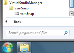
The vsmSnap application is launched from the Windows start menu under the path:
Start button -> All Programs -> VirtualStudioManager -> vsmSnap -> vsmSnap
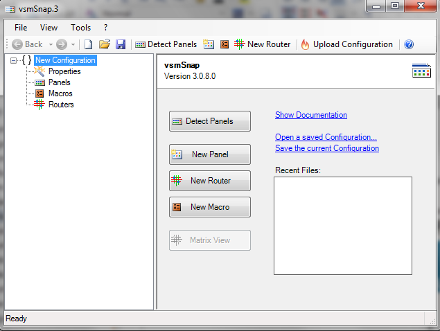
On startup, you will always see a New Configuration with an empty set of Properties, Panels and Routers in the "Configuration Tree" (on the left of the window):
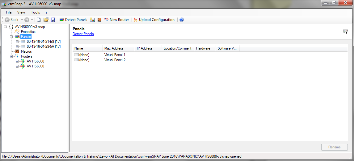
To open an existing configuration, select File -> Open (or File -> Recent Files) and choose a *.snap file - the tree updates to show all configured Panels and Routers:
Use the + and - buttons to open and close the branches of the tree.
Select a component (e.g. a panel) - its settings and any options are displayed in the "Parameter Area" (on the right):
Operations can be actioned from dedicated buttons in the "Parameter Area", from the Toolbar and Main Menus, or from the right-click context menu in the "Configuration Tree":
In each case you will see the status of the last operation at the bottom of the display.
Note that, before you can program a panel's functionality, you will need to add both the Panel and its target Router to the current configuration - these steps can be performed in either order.
To clear the existing configuration and start afresh, select File -> New to create a new configuration.
Note that the Macros entry in the configuration tree is not supported in this version of the vsmSnap.exe software.
Adding a Controlled Device
All the routers/switchers you wish to control must be added to the configuration, manually, as follows. Note that the routers/switchers can be either online or offline to perform this part of the configuration.
- Select Routers and Add Router (or click on the New Router button in the toolbar) - the "Router Configuration" window appears:
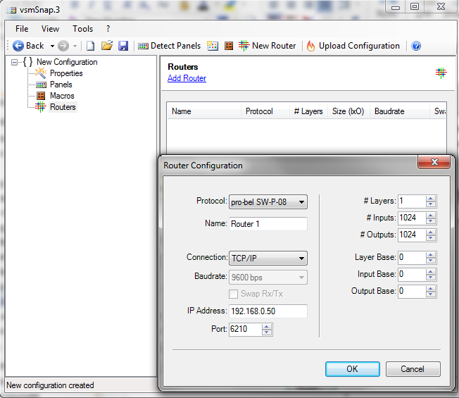
Edit the "Router Configuration" as follows:
Protocol select a protocol from the drop-down menu (e.g. pro-bel SW-P-08). Name enter a name for the Router. The name is used within the vsmSnap.exe software and is particularly useful if you are configuring multiple devices. Connection choose the connection type from the drop-down menu, either Serial - RS422 or TCP/IP. If using TCP/IP, the IP Address and Port number must be entered. IP Address enter the IP address of your Router. Port set the port number to 62010. 
Both the IP address and Port number MUST match those defined in the router/switcher's user interface earlier
# Layers, #Inputs, # Outputs
enter the number of layers (up to 4) supported by your Router, and the number of input and output signals (up to 1024) you wish to control. Layer Base, Input Base, Output Base
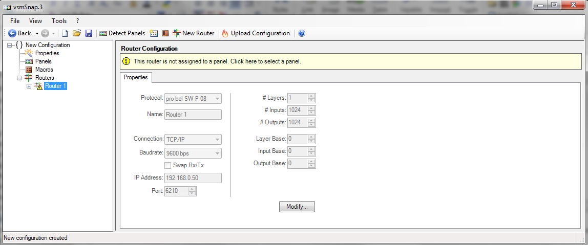
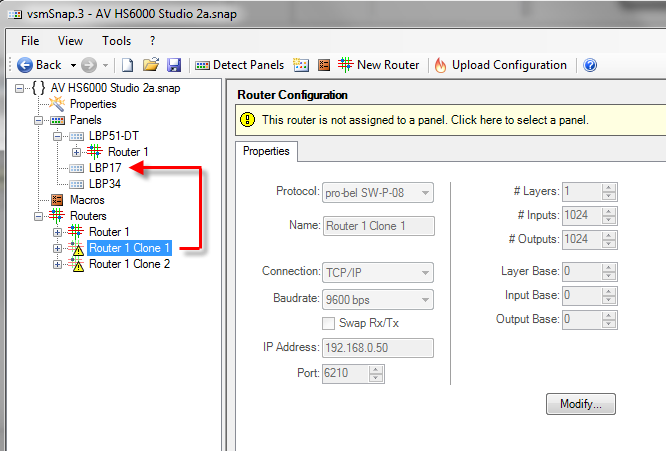
if your Router supports more inputs and outputs, then you can use these fields to apply an offset. For example, if you have specified 8 Inputs and an Input Base of 0, then it is the first 8 input signals from the Router which can be controlled. - When all the fields are complete, click OK - the Router is added to your configuration:

Note that the yellow hazard symbol beside the name is normal at this stage. It indicates that there is no panel assigned to the Router - Repeat these steps to add all the Routers required for your configuration. If you need to make changes, select the Router in the configuration tree and click on Modify - this will re-open the "Router Configuration" window.
To delete an existing Router, select it in the configuration tree, right-click and select Remove Router:
Defining the Signals
Once a Router has been added to the configuration, you can edit its signal names and labels, and set any crosspoint restrictions.
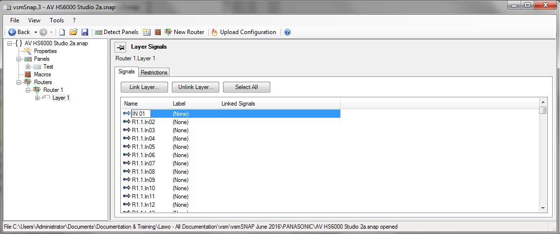
- Open up the Routers branch of the configuation tree and select a layer - e.g. Layer 1. You will now see two tabs in the parameter area: Signals and Restrictions:
- Select the Signals tab to edit the signal names and labels. In a new configuration, all signals are given a generic Name and an empty Label as shown above. In our example, R1.1.In01 = Router 1, Layer 1, Input 1. Empty label fields are always identified by the text: (None).
Both fields can be edited as described on the next page.
Bear in mind that the signal Label is what you will see on source and target select buttons during the operation of the panel (if no Button Label is defined):
It is also used within the configuration software: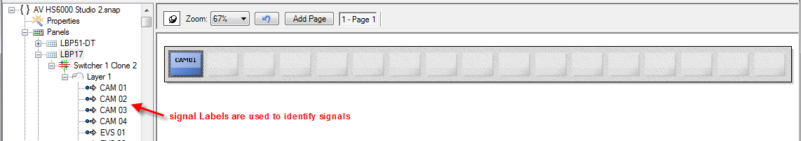
If the Label field is left empty, then the Name field will be displayed (both on the panel and in the configuration software). Every signal MUST have a Name; you cannot delete the Name field.
Note also that the text is automatically resized to fit the panel's LCD displays. For example, a shorter Label (CAM 1) will appear larger than a longer label (CAMERA 1). To remain legible, up to 12 characters are advised.
Editing Signal Names & Labels
- To edit a Name or Label, simply type your text into the field and press Enter
- To delete a Label, click to select the field, press DELETE on your keyboard, and then Enter - the entry updates to show (None).
Note that you signal Names cannot be deleted.
Shortcuts for Editing Multiple Entries
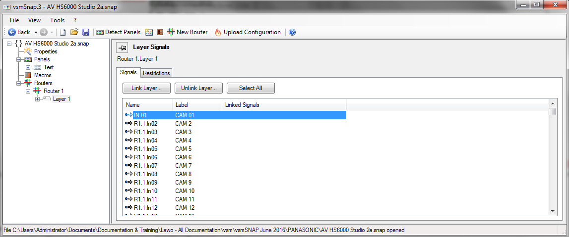
If you add an incremental value to the end of an empty Label field, then the software will auto complete all subsequent (None) Labels. This can be a fast way of labeling all inputs or all outputs - for example:
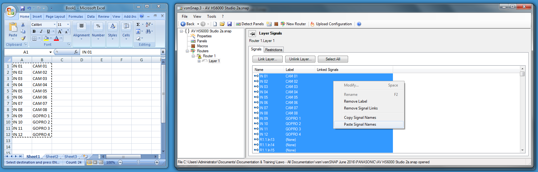
Alternatively, if you have lots of different Names and Labels to enter, you can copy and paste the entries from an Excel spreadsheet:
- First, create a spreadsheet with the text entries. Then select and copy both columns.
- Then, in vsmSnap.exe use the Select All button to select all signals. Right-click on any signal field and choose Paste Signal Names - the copied fields are entered:
- Or, to insert a range of Names and Labels, repeat as above, but press SHIFT on your keyboard to select a consecutive range of signals:

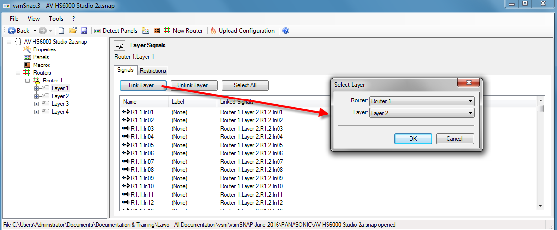
Linking Layers
If your Router supports more than one layer, you can choose whether signal Names and Labels are linked between layers using the Link Layer... and Unlink Layer... buttons:
Crosspoint Restrictions
- Select the Restrictions tab to define any crosspoint restrictions. This can be used to prevent specific connections such as CAM 01 connecting to MON 01; CAM 02 to MON 02; and so on:

- Click on an individual crosspoint to add or remove a restriction - a red X appears when a restriction is set.
- Use the Set 1:1 button to restrict all similarly numbered crosspoints: In 01 to Out 01; In 02 to Out 02; and so on.
- Click on the Clear button to remove all restrictions.
If your Router supports more than one layer, then you can use the Copy to all Layers button and Edit all Layers option. With a single layer, these options have no function.
Adding a Panel
All the panels you wish to configure must be added to the configuration, manually, as follows. If your panels are powered and connected to the network, then the quickest method is to use Detect Panels. Alternatively, if you are preparing a configuration offline, you can add a virtual panel now and then edit the physical panel's MAC address later.
Online Method (Detect Panels)
To use this method, all panels must be online and have a valid IP address for your network.
- If you have not already done so, run vsmDiscover to detect all panels connected to the network and configure the appropriate TCP/IP settings.
- In the vsmSnap.exe configuration tree, select Panels and Detect Panels (or click on the Detect Panels button in the toolbar) - the Panels list and configuration tree updates accordingly:

If a panel has not been detected, then check the following:
- Is it powered and connected to the network?
- Does the panel have a valid IP address for your network? See Connecting & Configuring the Network.
- Is the panel vsmSnap-enabled and running the correct firmware? The firmware revision must be >= 3.0.
- Are there any protocol restrictions in your network? If so, try the Poked Devices function explained later.
Offline Method (New Panel)
This method can be used if you are preparing a configuration offline, or the physical panel is not yet installed or connected.
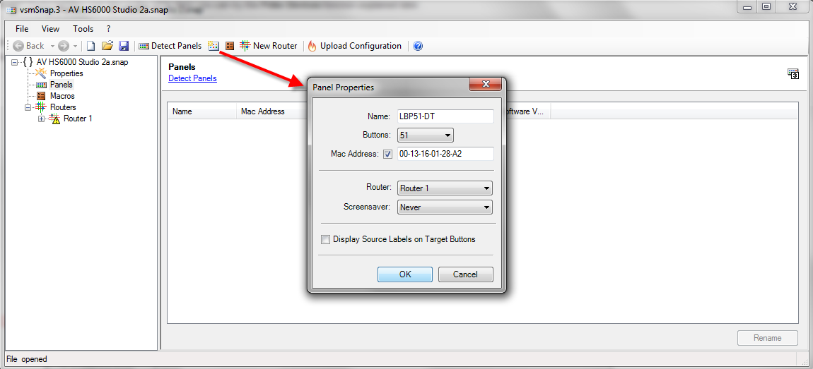
From the toolbar, select the New Panel button - the "Panel Properties" window appears:
Edit the "Panel Properties" as follows:
Name enter a name for the panel. The name is used within the vsmSnap.exe software and is particularly useful if you are configuring multiple devices.
Buttons select the number of buttons from the drop-down menu. This MUST match the number of buttons on the physical panel and cannot be edited later. MAC Address if you know the Mac address of the panel, tick the check box and enter the address here. The Mac address can be found on a sticker beside the RJ45 Ethernet connector on the vsmSnap panel.
If the Mac Address is unknown, leave the check box unticked and continue. You can edit the Mac address later.
The MAC address is what identifies each panel to the network. However, all communication, including the transfer of configuration data, is handled via TCP/IP. Therefore, once a panel is connected to the network, you will need to enter its Mac address in the configuration (as shown above) AND run vsmDiscover to map its Mac address to an IP address that is valid for your network.
Router select the target Router you wish to control from the drop-down menu. If you have not yet configured any Routers, then leave this field blank and assign a Router later.
Note that, within the configuration, you can assign one Router to one Panel at a time. Therefore, if you wish to control the same target device from multiple panels, you will need to make copies of the Router definition first. See Assigning the Target Router.
Screensaver select an option from the drop-down menu. By enabling the screensaver you can prolong the lifespan of the LCD button displays. Display Source Labels on Target Buttons tick this check box if you wish to display the source label below the target label on a target LCD button. If unticked, only the target label is displayed.
When all the fields are complete, click OK - a virtual panel is added to your configuration:
Repeat these steps to add all the panels required for your configuration.
If you entered the panel's Mac address in step 2, then as soon as the panel is connected to the network and configured using vsmDiscover, it will be "seen" by the configuration software. If you left the MAC address empty, then you will need to enter this later.
To make changes, select the panel in the configuration tree and click on Modify - this will re-open the "Panel Properties" window:
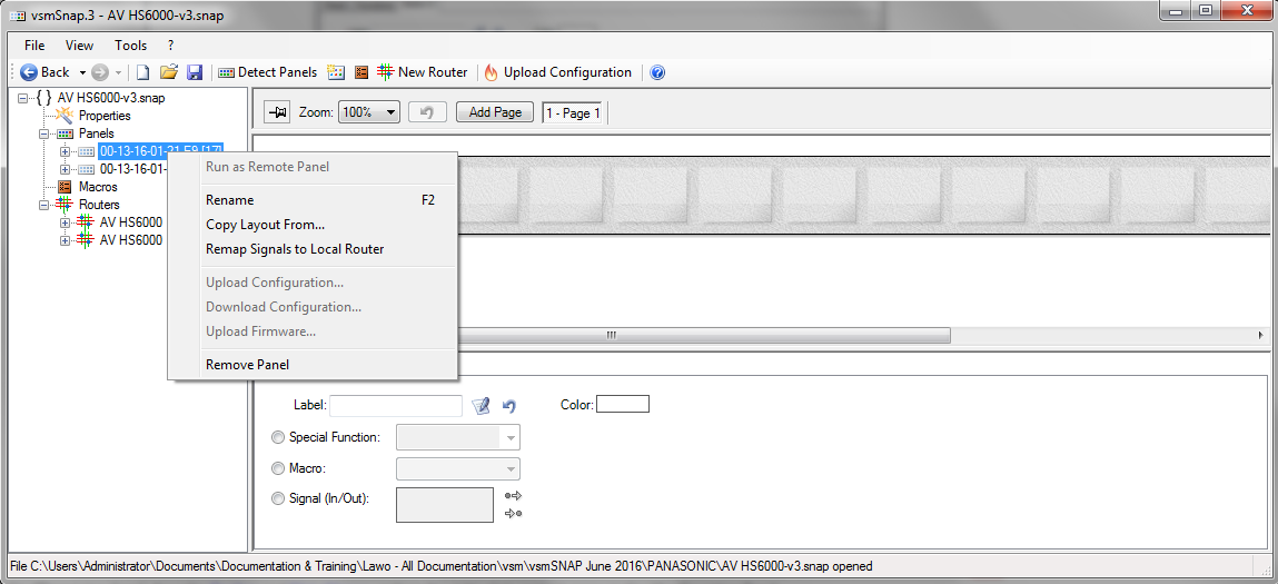
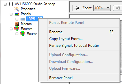
To delete a panel, select it in the configuration tree, right-click and select Remove Panel:
Attaching the Target Device
Each vsmSnap panel can control a single router/switcher, while the same router/switcher can be controlled by multiple panels if you wish.
Note that, within the configuration, you can attach one Router to one Panel at a time. Therefore, if you wish to control the same target device from multiple panels, you will need to make copies of the Router definition first.
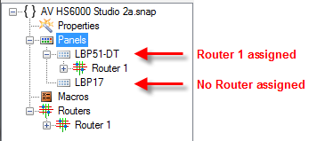
You can check the current assignments by interrogating the configuration tree:
To clone the Router definition:
- First make sure that the Router configuration is complete, with all signal names, labels and crosspoint restrictions defined as you wish. If not, you will need to redo the cloning at a later stage.
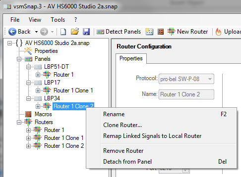
- Then select the Router in the configuration tree, right-click and select Clone Router... - a configuration window appears where you can enter a new Name for the clone.
Leave or edit the other fields so that they match those of the copied device.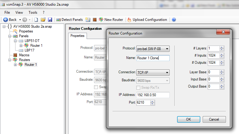
- Select OK to add the Router to the configuration.
- Repeat steps 2 and 3 until you have created a Router definition for every panel you wish to assign.
To assign a Router to a Panel:
There are a number of ways to assign the target Router to each panel, but the simplest is to drag and drop a Router definition onto a panel from the configuration tree:
Once assigned, the exclamation mark beside the Router name disappears and the tree hierarchy updates accordingly:
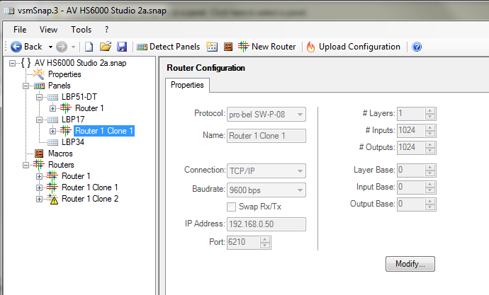
Note that if you drag and drop onto a panel with an existing Router assignment, then the previous assignment will be replaced. Repeat the assignments until all panels are assigned to their target Routers.
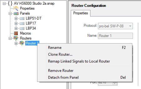
To delete an assignment, open the panel branch of the configuration tree, select the Router assignment, right-click and select Detach from Panel:
Defining the Buttons
Once a Router has been attached, the next step is to populate the panel. Each LCD button can be assigned a function, label and color, and each panel can support multiple pages. When configuring a button, there are two main types of function:
- Source and Target Select buttons - to control crosspoint routing within the attached router/switcher.
- Special Functions - such as page navigation, lock panel, etc.
Basic Principles
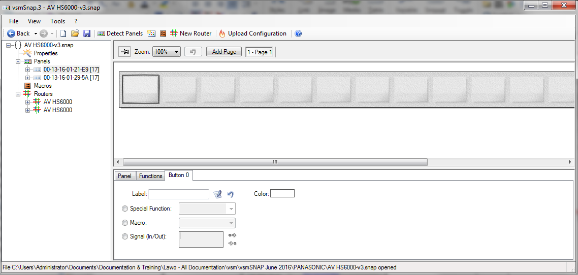
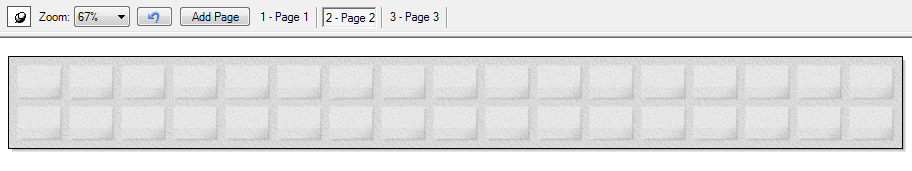
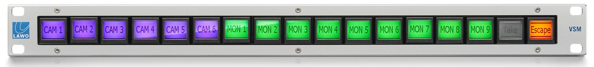
- Select a panel in the configuration tree and look at the top half of the "Parameter Area" - here you will see a visual representation of the panel (the panel view):
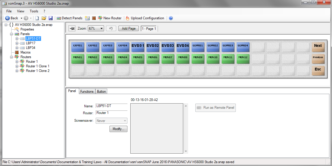
If no functions have been assigned, then you will see a series of empty "greyed out" buttons. If you are editing an existing configuration, then the button labels and colors are displayed (as shown above). - Use the drop-down Zoom menu to resize the panel so that it fits within your configuration window.
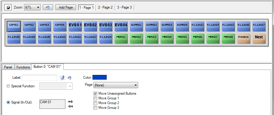
In our example, we have a row of source select buttons (blue), a row of target select buttons (green), and some special function buttons to navigate through the pages (orange).
The options to the right of the Zoom menu allow you to add or view additional pages. The button, to the left of Zoom, can be used to "pin" the current view. This will be explained later.
In the lower half of the window are three tabs: Panel, Functions and Button. - Select the Panel tab and Modify to edit the "Panel Properties" (described earlier).
Note that the Run as Remote Panel option is not supported in this version of the vsmSnap.exe software. - Select the Functions tab to assign a special function.
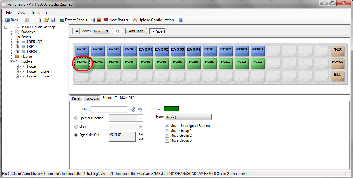
- Select the Button tab to create a source/target select button, or configure the other button options. In each case, select a button (from the panel view) and then define its label, function and color.
In our example, the first button on the middle row has been configured to select the Signal Out labeled MON 01.
To undo the last assignment, click on the Undo button ![]() at the top of the panel view.
at the top of the panel view.
To move the position of a button (e.g. MON 01), drag and drop the button from its old to new position in the panel view.
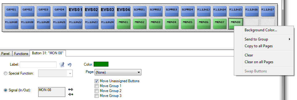
To clear a function, right-click on a button and select Clear:
Creating Source & Target Select Buttons
While you can create source/target select buttons from the Button tab, it is usually quicker to drag and drop signals from the configuration tree onto the panel view as follows:
- Select the panel you wish to define in the configuration tree (e.g. LBP34), followed by a page (e.g. 1 - Page 1):

- Click on the "pin" button
 located at the top left of the panel view (to the left of Zoom) - the icon will change to
  , indicating that the current view is now "pinned down". In this mode you can make selections within the configuration tree while keeping the current panel in view.
 - Open the branches of the panel's target Router to select the signals you wish to assign:
- Either, click once to select an individual signal.
- Or, select a range by clicking on the first signal, holding down SHIFT on your keyboard, and clicking on the last signal in the range.
In our example, we have selected the first 24 input signals:
- Drag and drop the selected signals from the configuration tree onto the first button you wish to assign - the signals are assigned incrementally from left to right, and then top to bottom, across the panel to create 24 source select buttons (their default Color is blue). Note that if any of the buttons are already assigned, then their functions will be overwritten.

- Repeat this process to configure more source or target select buttons. In the example below, we have assigned the first 8 output signals to the next set of free buttons to create 8 target select buttons (their default Color is green).

- Once you have finished configuring the panel, click again on the "pin" icon to unlock the pinning.
Assigning Special Functions
You can use a similar method to assign any of the special functions, by dragging and dropping a function from the Functions tab onto a button in the panel view:
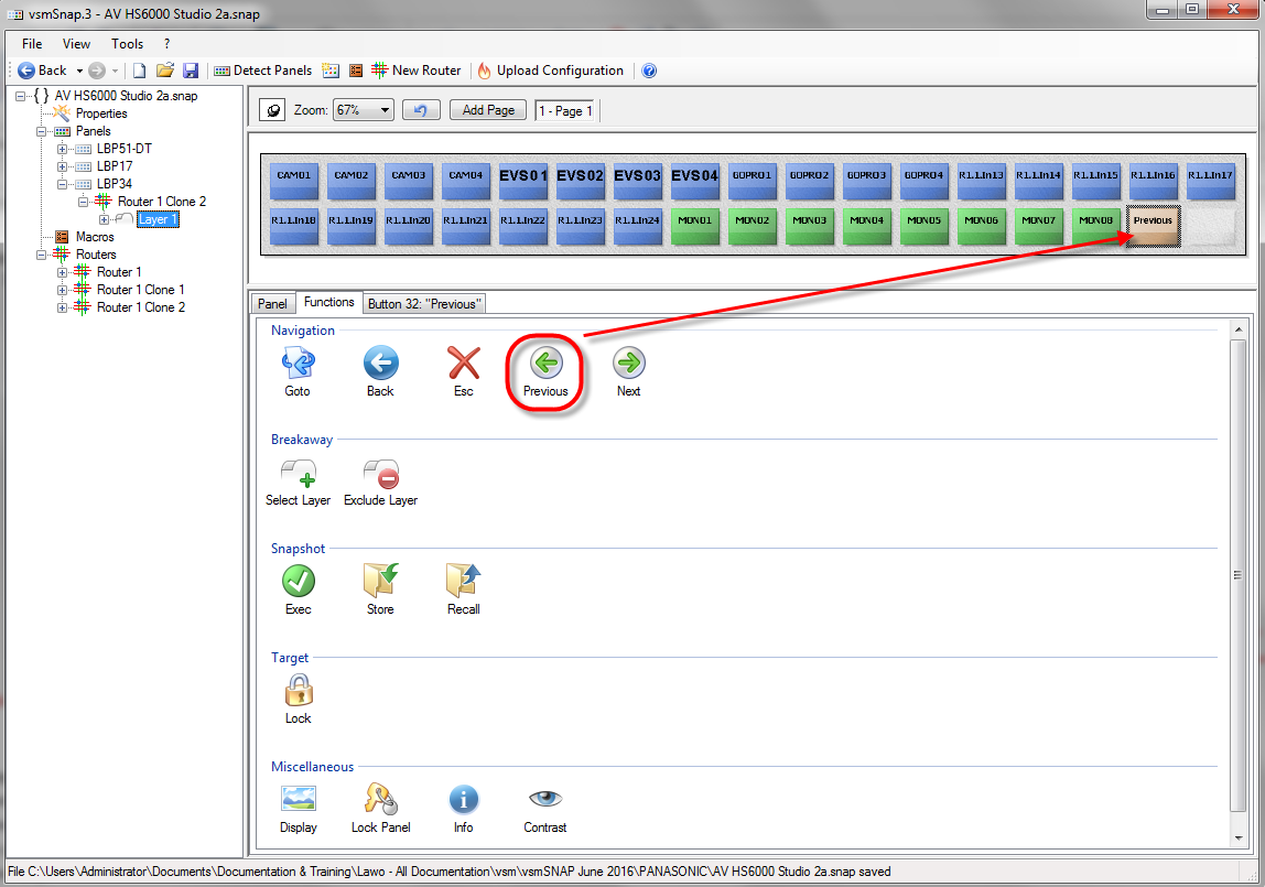
The special functions are divided into categories as follows:
Page Navigation
- Next - steps forward to the next page.
- Previous - steps back to the previous page.
- Esc - jumps to Page 1 and deselects all targets.
- Back - returns to the last used page.
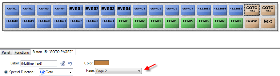
- Goto - jumps to a specific page. Select the Button tab to choose the page number (e.g. Page 2):
Breakaway
These functions apply if the target Router supports multiple layers. You can use them to "breakaway" crosspoint switching between layers - for example, to switch only the crosspoints on a video layer:
- Select Layer - enables crosspoint switching on selected layers only.
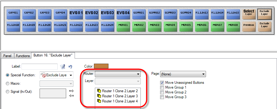
- Exclude Layer - disables crosspoint switching on selected layers.
In each case, select the Button tab to choose which layers will be selected or excluded (e.g. Layers 2, 3 and 4):
Snapshot
vsmSnap can store and recall the state of the Router's crosspoints using snapshots. Up to 16 memory banks are available, each storing 16 crosspoint states.
- Exec - takes up to 16 selected crosspoints.
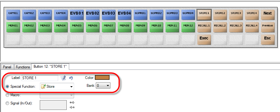
- Store - stores the selected crosspoints into a memory bank (1 to 16).
- Recall - recalls the selected crosspoints from a memory bank (1 to 16).
For Store and Recall, select the Button tab to choose which bank is specified, taking note that the banks are numbered from 0 to 15 in the drop-down menu:
Target
- Lock - locks a specified target. Connections to locked targets cannot be changed.
Miscellaneous
- Display - this is a generic display button with no active function.
- Lock Panel - locks (or unlocks) the panel. When locked, all buttons are disabled. The operator must press and hold the button > 3 seconds to toggle the state.
- Info - displays panel status information in the button LCDs. The operator can press any button to cancel the "info" state.
- Contrast - allows the operator to adjust the contrast of all button LCDs.
Adding Pages
- To add more pages of functions, click on Add Page at the top of the panel view - each click adds a new page:
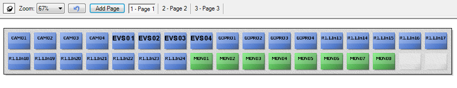
- Select one the page buttons to switch to the new page. You can now repeat the earlier steps to configure the button functions
- To rename or remove a page, right-click on the page select button:

- To provide the operator with page navigation, you will need to reserve some of the buttons on each page for the special functions: Next, Previous, etc. See Special Functions for details.
Attention: Do not configure more than a total of 64 pages into a panel.
The Button Tab
The Button tab offers an alternate method for assigning source/target or special function buttons, plus it includes options such as the button Label and Color:
Assigning Functions from the Button Tab
- From the panel view, select the button you wish to assign.
- From the Button tab, select either a Special Function from the drop-down menu.
Or, click on the "Select Input" (or "Select Output") arrow buttons, beside Signal (In/Out), to open a pop-up window where you can choose an input (or output) signal. Once assigned, the Label or Name of the signal is shown in the Signal (In/Out) box. - Edit the button Label and Color fields as described on the next page.
Note that the other options (Move Unassigned Buttons, etc.) are not supported in this version of the vsmSnap.exe software.
Button Label
Each button has its own Label field which will override the signal label for source or target select buttons, or the software's own default label for special function buttons.
For example, to use the signal labels defined in the Router signal list earlier, you should leave the button Label field empty (as shown above). In this instance, the signal label (e.g. CAM 01) will be displayed. Remember that if no signal label is defined, then the signal name (e.g. R1.1.In01) will be displayed.
Alternatively, you can override the signal label by entering some text into the button Label field:
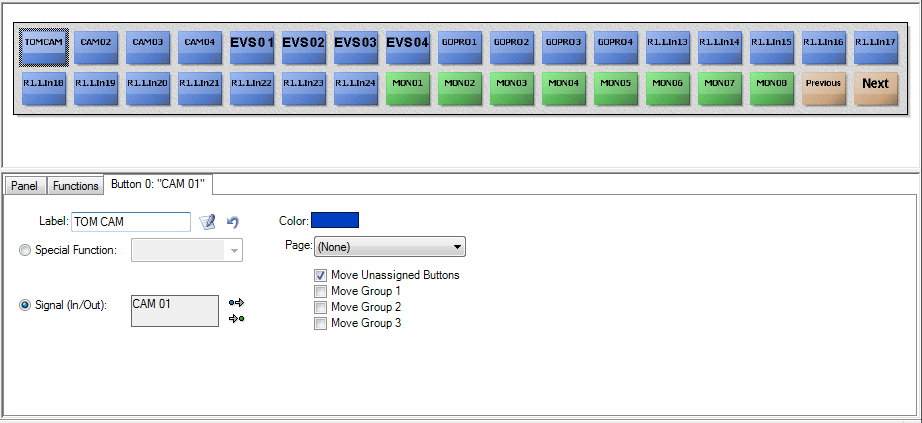
Use the two button beside the Label field to clear the label (and revert to the signal label), or open the button label editor (to customise the look of the text):
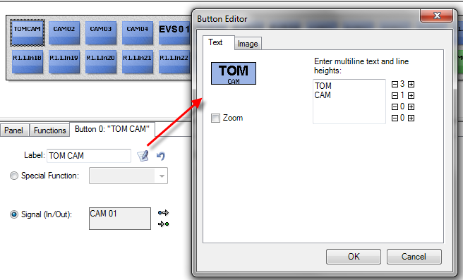
Note that the text is automatically resized to fit the panel's LCD displays. This means that a shorter Label (CAM 1) will appear larger than a longer label (CAMERA 1).
To remain legible, up to 12 characters (wide) are advised.
Button Color
When a function is assigned, the button is given a default color: blue for source select; green for target select; orange for page navigation; and so on.
If you wish, you can override the default color, by making a selection from the Color field:

Uploading Configuration Data
Having configured a panel and its target Router, the next step is to upload the configuration data. Following a successful upload, the data is stored on the panel and loads at boot up.
Note that you can use this method, at any time, to update a panel's functionality.
- From the toolbar, select the Upload Configuration button - a dialogue box opens listing all the panels detected on your network.
Use the tick boxes to select which panels you wish to upload to:

If the list is empty, then make sure all panels are connected and correctly configured for your network.
If any of the panels are highlighted in red, then this means that they have been discovered on the network (from their MAC address) but have an invalid IP address.
In this instance, use vsmDiscover to edit the IP settings accordingly.
Each panel MUST have a unique IP address which resides within the same IP range and subnet as the target Router.
- Having selected the panels, click on Start - a dialogue box appears asking for the Password. (This is required to prevent an accidental upload to the panel).
- Type in the Password: the default = 1234
(If you wish, you can change the password: select Change Password, and then enter the new password twice. The new password is stored on the panel following the upload.)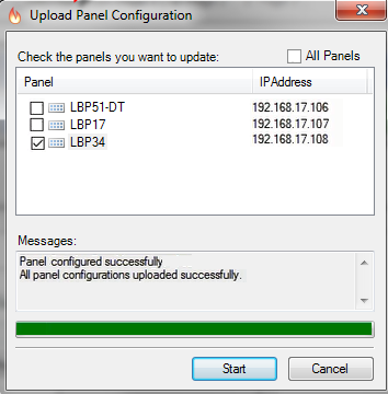
- Select OK to start the upload - the Messages area shows the status and progress:
After a successful upload, you will see the following confirmation and the panel will reboot - this may take a few seconds. It will now be running the configuration you have just have uploaded.
If you see an upload failure message, then check the network connection and configuration.
If the upload appears to be successful but the panel is not running the correct configuration, then the transfer could have incurred an invalid checksum. Try uploading the configuration again and make sure that vsmDiscover is NOT running.
Testing the Operation
As soon as a panel has established network communication with its target router/switcher, the blue LED on the rear of the panel will begin to flash, and you should be able to set crosspoints:
First, press a target select button (e.g. Monitor 01), followed by a source select button (e.g. Camera 01) - the connection should be set.
Troubleshooting the Router Connection
If the panel does not seem to be communicating with the Router, then check the Network (or Serial Interface) settings, and the Layer Base and Input/Output Base, defined in the vsmSnap Router configuration window. And, the similar settings configured in the third-party device. See Configuring the Switcher and your product's documentation for more details.
Saving & Loading Configuration Files
The complete configuration for all panels and Routers can be saved and loaded on your PC, as *.snap files. It is recommended that you save regularly to backup your configuration as you work.

To save the current configuration
- Select either File -> Save, or File -> Save As, from the main menus and enter a suitable file name - the file is saved onto your PC as a *.snap file.
Note that it is important to retain the suffix, otherwise vsmSnap.exe cannot open the file. - From here on, you can use File -> Save (or click on the Save icon on the toolbar) to update the file.
The file name appears at the top of the configuration tree (e.g. AV HS6000-v3)
To open an existing configuration
- Select either File -> Open (or File -> Recent Files) and choose a *.snap file - the configuration tree updates to show all configured Panels and Routers.
- If have opened a configuration in order to change the functionality of a panel, then remember to upload the data to the panel across the network.
Other Functions
Poked Devices
This function in the Tools menu may be needed if a protocol called "UDP-broadcast" is restricted in your network.
In this instance, the Detect Panels function will not automatically find your vsmSnap panels. Therefore, you will need to set up a list of panels, manually, as follows:
- Select Tools -> Poked Devices... to open the dialogue box:
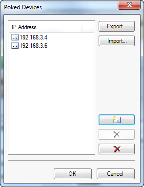
- Use the Add Panel button to enter an IP address for each panel on your network.
From here on, vsmSnap.exe will use the IP addresses in this list, rather than UDP Broadcast, to detect all panels. - Use the X buttons to clear a selected address or the complete list.
- Use the Export button to export the list (as a .txt file). This allows you to Import the list on another configuration PC if you wish to edit the configuration on a different computer.
The Main Menus
Where indicated, you can use the keyboard shortcuts to select a menu option. Note that the most commonly used functions are also duplicated on the toolbar.
The File Menu
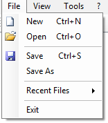
- New - opens a new "empty" configuration. Before using this option, you should take care to save any changes to the existing configuration using Save or Save As.
- Open - opens a configuration file from your PC. Configurations are stored as *.snap files.
- Save and Save as - saves the current configuration onto your PC as a *.snap file.
- Recent Files - select an option from this menu to open a recently saved file.
- Exit - closes the configuration software application.
The View Menu
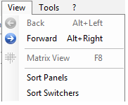
- Back and Forward - step backwards and forwards through the last few tree selections. You can use this to switch quickly between different configuration views - for example, from a Panel to a Router.
- Matrix View - this option is not supported in this version of the vsmSnap.exe software.
- Sort xxx - use these options to sort the configuration tree components in alphabetical order.
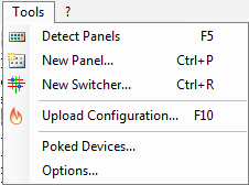
The Tools Menu

- Detect Panels - detects all online panels, see Adding a Panel (online method).
- New Panel... - adds a new virtual panel, see Adding a Panel (offline method).
- New Router... - adds a new Router, see Adding a Switcher.
- Upload Configuration... - uploads the current configuration data to all or selected panels, see Uploading Configuration Data.
- Poked Devices... - see Other Functions.
- Options... - opens a dialogue box where you can set the default options for Button Colors, etc.
The ? Menu
- About - opens the "About this Software" dialogue. You can check the vsmSnap.exe version from here