HOME - IP Senders and Receivers
In order to send and receive content to and from the network, the device must have some senders and receivers. For some devices, the senders and receivers are pre-defined, while for others they must be created by the user.
You can check the current configuration by opening the "Device Details" page and selecting the Senders and Receivers tabs.
- If there are existing senders and receivers, then you can go straight to the Stream Routing page (to connect the streams).
- If the list is empty, then please follow the instructions below to create some new senders and receivers.
New Sender
The New Sender button can be used to create one or more streams (to publish content from the device to the network). Once created, you can connect the senders to other receivers on the network (via the Stream Routing page).
1. From the main "Devices" page, click on the label of the device you wish to configure.
This opens the "Device Details" page with the General tab selected.
2. Select the Senders tab to view the existing senders.
In the example below, there is one existing stream with the label "A64-TX".
3. Click on the New Sender button and follow the on-screen instructions.
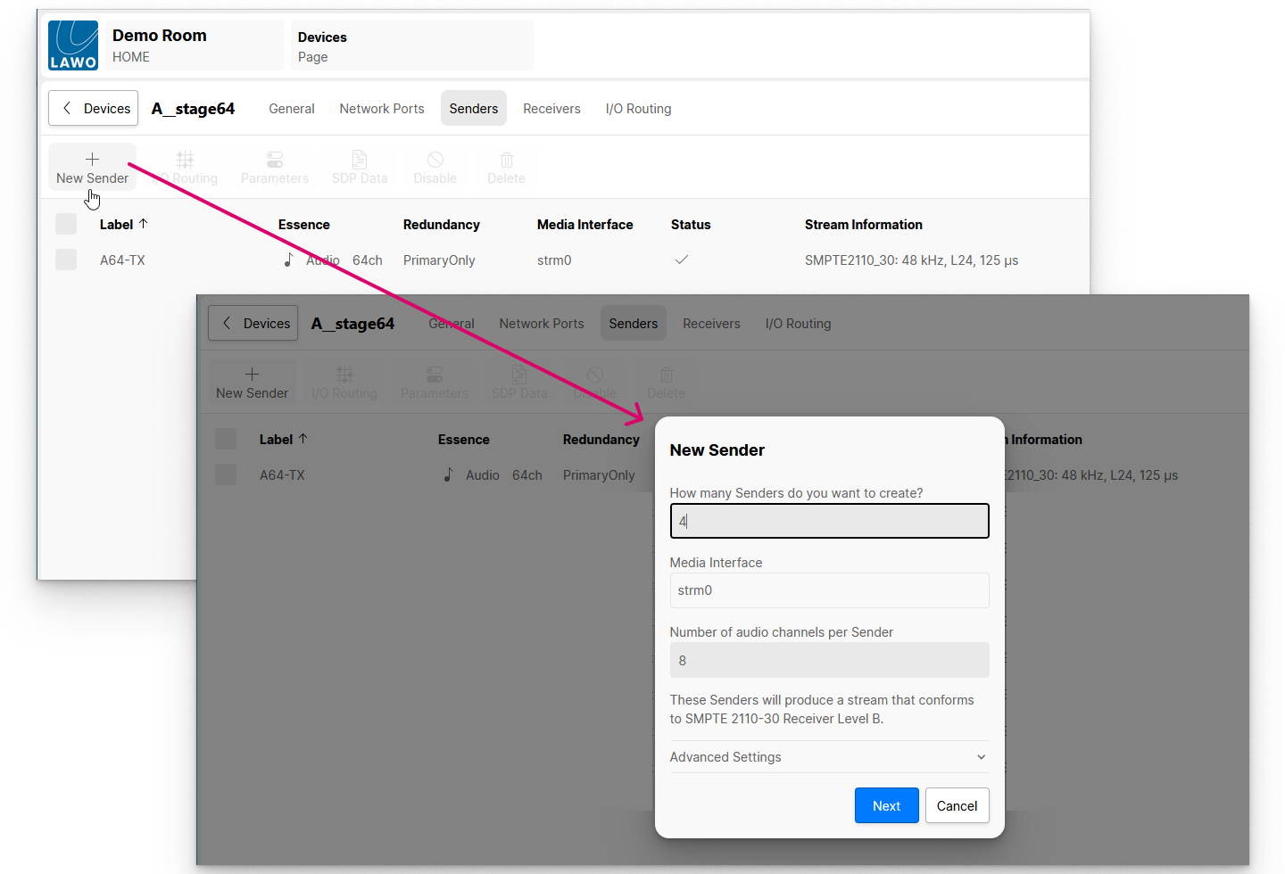
To simplify the operation, the "New Sender" window opens with some default values and the advanced settings are hidden.
- To change the number of senders or any of the other values, edit the fields as required. The example above will create four 8-channel senders that conform to SMPTE 2110-30 Receiver Level B.
- The Advanced Settings can be opened if you need to adjust the streaming parameters (described later). In most instances, it is fine to leave these hidden and use the default values.
The stream size is defined by the number of channels, codec type and frame size. This is important if network bandwidth is an issue. Thus, the network topology should be considered before defining the channel count for senders and receivers.
4. Select Next to continue, and enter a label for the first sender (e.g. Tx-1).
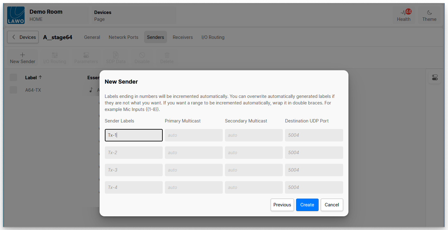
The remaining fields auto-complete as you type into the first field. If the label ends in a number, then this increments.
You can use double braces to enter an auto-incrementing range. For example, when creating 8-channel streams. you could type Tx {{1-8}} to enter the sender labels: Tx 1-8, Tx 9-16, Tx 17-24, etc.
The identifier string must not contain the character “/” (ASCII/UTF-8: 47) and must begin with a letter or the lower line character “a”-“z”, “A”-“Z”, “_” (ASCII/UTF-8: 65-90, 97-122 ,95).
Sender labels must not exceed 28 characters.
The Primary Multicast, Secondary Multicast and Destination UDP Port fields determine how the multicast addresses are created. There are two possibilities: either automatic or manual.
- If you leave the fields at their default values (auto and 5004), then the stream will be allocated an automatic multicast IP address and port. In most instances, this is fine. You can view the allocated addresses once the stream is created (by selecting the stream and clicking on Parameters).
- If your network supports a limited IP range, then you may wish to assign a multicast IP address and port manually. In this instance, type the required values into the corresponding fields.
5. Select Create to create the streams.
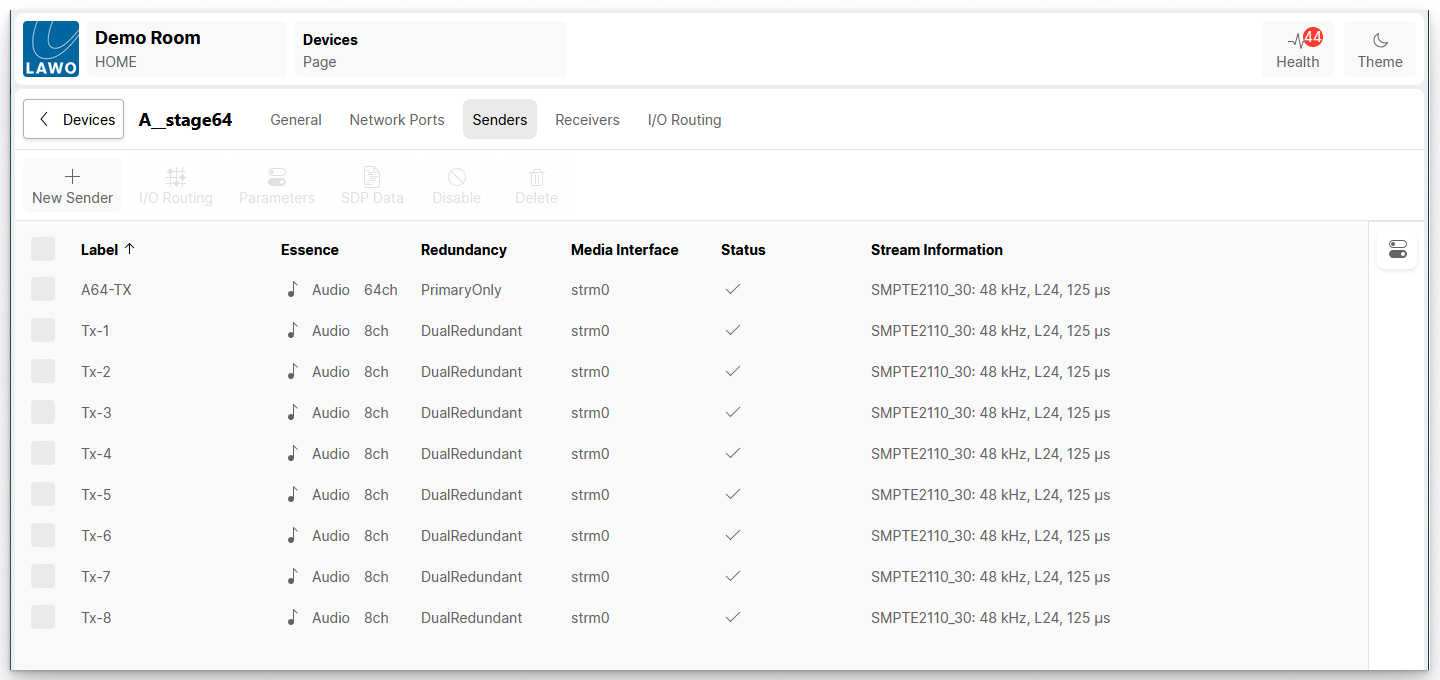
The sending streams are added to the list of Senders. In our example, the final result looks like this.
New Receiver
The New Receiver button can be used to create one or more new receivers. Once created, an incoming stream can be assigned to the receiver either by making a connection in the Stream Routing page or editing the receiver's SDP data.
1. From the main "Devices" page, click on the label of the device you wish to configure.
This opens the "Device Details" page with the General tab selected.
2. Select the Receivers tab to view the existing receivers.
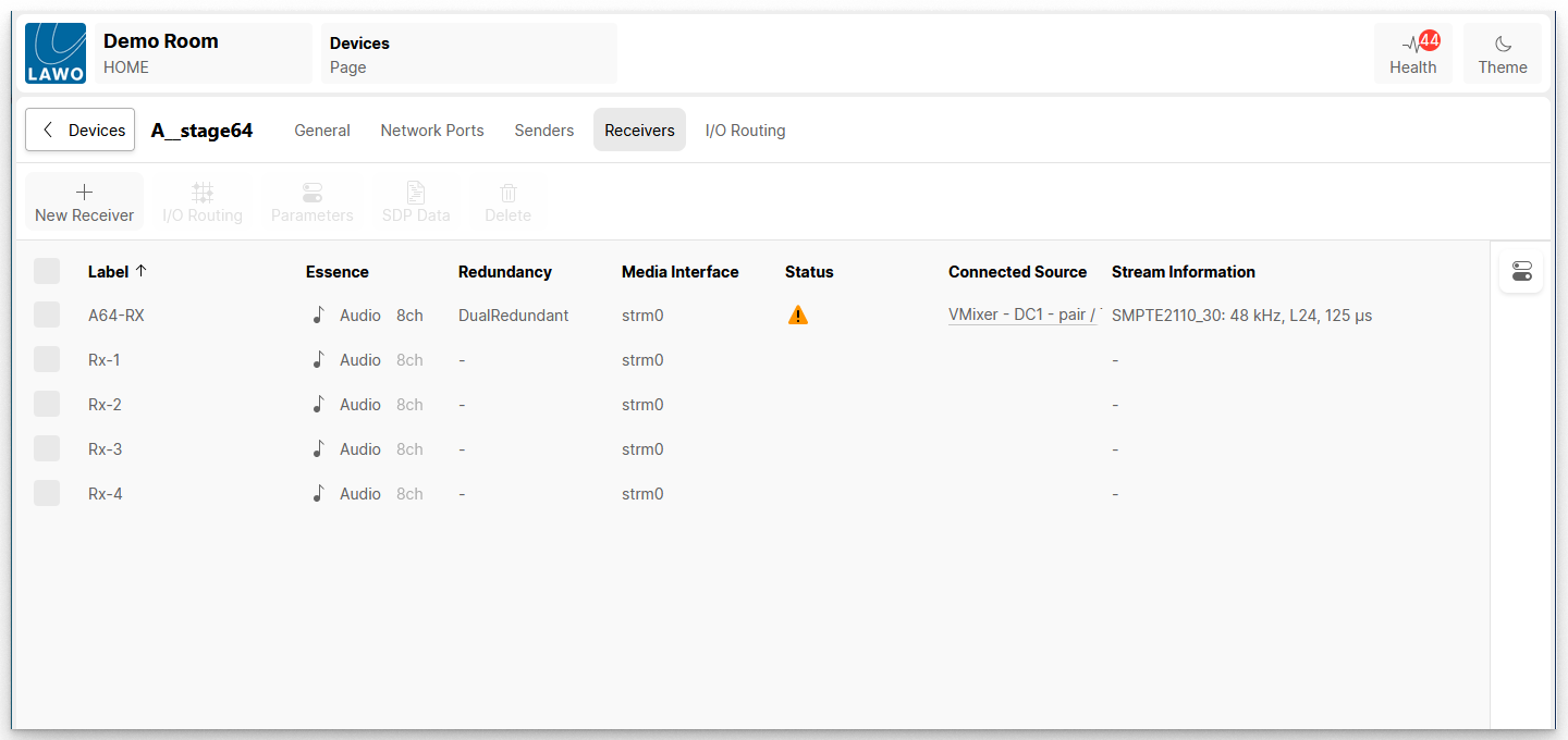
In the example below, there is one existing receiver with the label "A64-RX".
3. Click on the New Receiver button and follow the on-screen instructions.
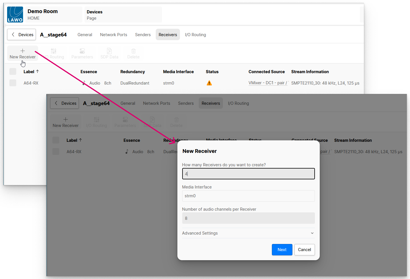
To simplify the operation, the "New Receiver" window opens with some default values and the advanced settings are hidden.
- To change the number of receivers or any of the other values, edit the fields as required. The example above will create four 8-channel receivers.
- The Advanced Settings can be opened if you need to adjust the streaming parameters (described later). In most instances, it is fine to leave these hidden and use the default values.
By default, all new receivers are configured to use two network ports in Dual Redundant mode so that they can accept SMPTE ST2022-7 compatible streams (for redundant streaming).
The "Number of audio channels per Receiver" sets the maximum number of channels that can be received. Once an incoming stream is connected, if there is a mismatch, then the incoming channels are received on a best-effort basis. For example:
- If a stereo stream is connected to an 8-channel receiver, then the two source channels are assigned to channels 1 and 2 of the receiver (and channels 3 to 8 of the receiver are unused).
- If a 64-channel stream is connected to an 8-channel receiver, then the first eight source channels are assigned to channels 1 to 8 of the receiver (and the remaining source channels from the incoming stream are unused).
4. Select Next to continue, and enter a label for the first receiver (e.g. Rx-1).
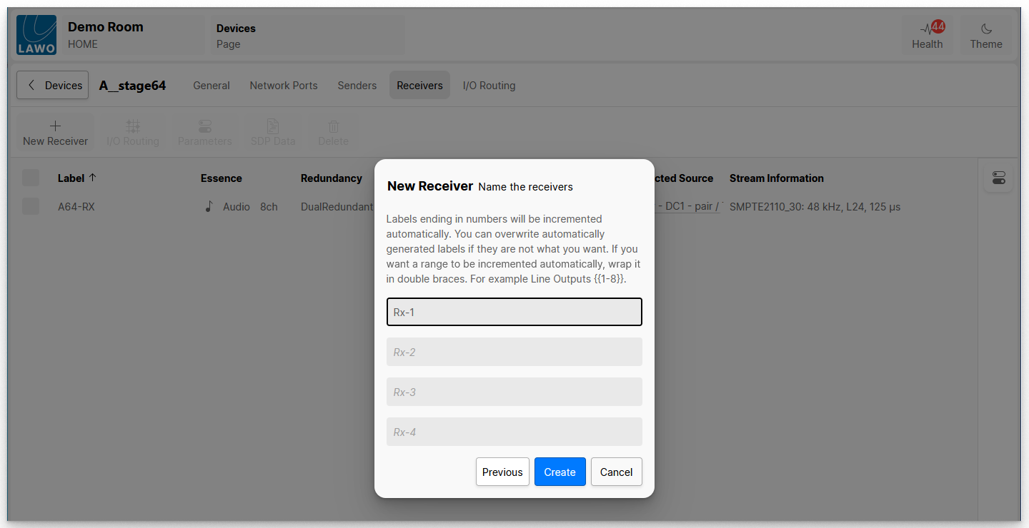
The remaining fields auto-complete as you type into the first field. If the label ends in a number, then this increments.
You can use double braces to enter an auto-incrementing range. For example, when creating 8-channel receivers. you could type Rx {{1-8}} to enter the receiver labels: Rx 1-8, Rx 9-16, Rx 17-24, etc.
The identifier string must not contain the character “/” (ASCII/UTF-8: 47) and must begin with a letter or the lower line character “a”-“z”, “A”-“Z”, “_” (ASCII/UTF-8: 65-90, 97-122 ,95).
Receiver labels must not exceed 28 characters.
5. Select Create to create the receivers.
The new entries are added to the list of Receivers. In our example, the final result looks like this.
