.edge - Controls, Connectors and Indicators
All controls, connectors and indicators are located on the front and rear panel, with the exception of the grounding screw (10).
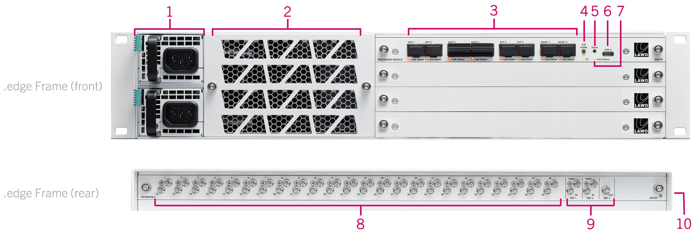
1. Power Supplies x 2
- You will hear the fans speed up when power is first applied. This is normal. The fan speed will settle once the operating temperatures of all processing blades have been determined (by the master blade).
- The processing blades take approximately 40 seconds to boot from power on.
- At the end of the boot-up, each processing blade loads the latest settings (stored at shut-down).
- LED 1 (power) - lights in green when the power is ok.
- LED 2 (fault) - lights in amber if there is a fault or warning.
The table below describes all possible states.
| PSU LED | Condition(s) | Meaning | Recommended Actions |
|---|---|---|---|
1 - Off | No power. | No AC (or DC) input. | Check the AC mains supply and IEC connection. |
1 - Green (blinking) | Standby ON; Main output OFF; AC (or DC) present. | AC (or DC) input detected; PSU is starting. | Wait for PSU to start. |
1 - Green (solid) | Standby ON; Main output ON. No errors detected. | PSU is active; no errors. | Normal operation; no action required. |
2 - Amber (solid) | Main output overcurrent, undervoltage or overvoltage. | Internal fault. | Check the PSU Health pages (in HOME's Advanced parameters). |
2 - Amber (blinking) | Power supply warning event triggered. | Internal warning. |
2. Front Grill / Fans
.edge is cooled by five temperature-controlled fans (fitted behind the front grill).
- Air is taken in from the front and blown out, across the processing blades, to the right side.
- The fan activity is controlled automatically by the master processing blade.
The health of the fans can be interrogated using the Health pages (in HOME's Advanced parameters).
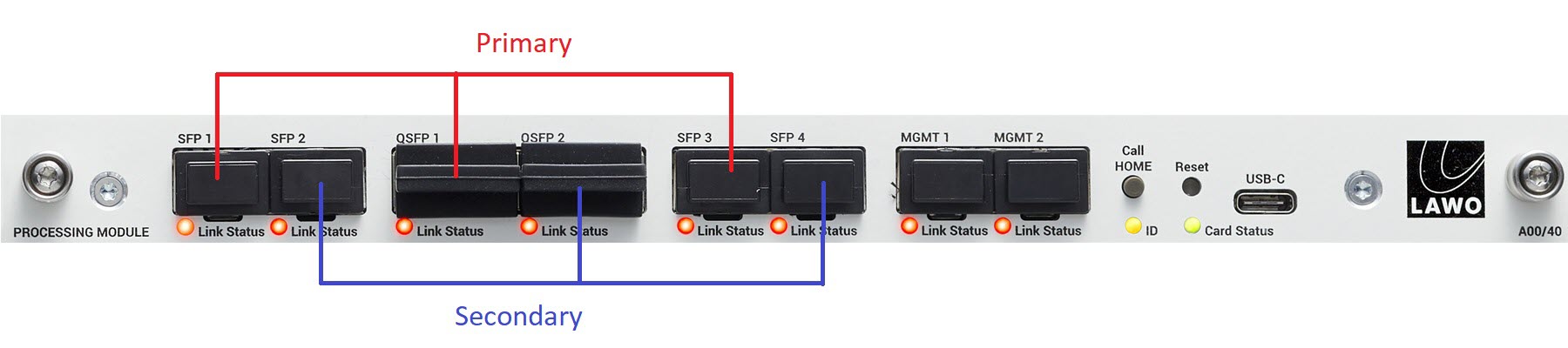
3. Network Interfaces
Each processing blade is equipped with 8 network interfaces: 6 media + 2 management ports.
- The media ports connect the IP streams to the media network(s). The active ports depend on the operating mode: either 4 x 25GbE (via SFP28) or 2 x 100GbE (via QSFP28).
- The MGMT ports connect the processing blade to the management network(s): 2 x 1GbE (via SFP).
| Link Status LED | Meaning | Recommended Actions |
|---|---|---|
Green | Link up (ok). | No action required. |
Yellow | Link down: optical transceiver detected but no connection. | Check the connection to the network switch. |
Off | Link down: optical transceiver missing. | Check the fitting of the optical transceiver. |
The link status and IP settings can also be interrogated using HOME's Network Ports tab.
The image below shows the location of the primary and secondary interfaces.
4. Call Home & ID
The Call Home (button) and ID (LED) can be used to identify the hardware in the HOME Web UI. This can be extremely useful when you are configuring more than one blade.
The ID LED has three possible states:
- Green (fully lit) = Identify Hardware inactive (normal state).
- Red to Blue, alternating = Identity Hardware active.
- Off = processing blade is off (no power).
To identify a processing blade, either press and hold Call Home (on the unit) for at least 2 seconds or select Identify Hardware (in HOME's General tab).
When Call Home or Identify Hardware is active, a “Says Hi” message appears in the HOME Web UI (as shown here).
To cancel the "Identify Hardware" mode, either deselect Identify Hardware (on the GUI) or press and hold the Call Home button again (on the unit).
The Call Home button can also be used to reset the network settings for the MGMT ports. This is described later in .edge - Network Settings.
5. Reset
The Reset button can be used to reset the power of the processing blade. The button is recessed to prevent accidental operation. After the reboot, the blade loads the latest configuration.
You can also reboot a processing blade remotely using the Reboot option (from HOME's "Devices" list).
A processing blade can be reset to its factory default settings using the Factory page (in HOME's Advanced parameters).
6. USB-C
The USB-C (port) is provided for diagnostics. In the event of a problem, you may be asked to connect this port to a service computer by a Lawo support engineer. The connection should be made using a standard USB Type-C cable.
7. Card Status
The Card Status LED shows the health of the processing blade (and chassis*). The LED has three possible states: green, amber or red.
| Card Status LED | Meaning | Recommended Actions | |
|---|---|---|---|
Green, intermittent | Ok | No action required. | |
Amber, intermittent | Warning | Check the Card Warning(s) on the System controls page (in HOME's Advanced parameters). | |
Red, blinking | Fault | Check the Card Fault(s) on the System controls page (in HOME's Advanced parameters). | |
*On the master processing blade (fitted to the highest physical slot), the Card Status LED shows the health of both the card (blade) and chassis (frame). Typically, the chassis faults are either power or fan-related. e.g. If there is a power fault in the frame, then the top Card Status LED lights in red while all other Card Status LEDs are green.
8. SDI Interfaces
Each rear I/O plate is equipped with 48 x HD-BNC for SDI interfacing.
The number of available SDIs is determined by the number of ".edge_sdi" licenses on the processing blade. In addition, the number of SDI inputs versus outputs can be changed using the Device Options (in HOME's General tab).
9. Reference Signal Interfaces
Each rear I/O plate is equipped with 5 x HD-BNC for external reference signals: 2 x REF IN, 2 x REF THRU and 1 x REF OUT.
The sync reference can be checked or changed using the Synchronization parameters (in HOME's Advanced parameters ).
10. Grounding Screw
A grounding screw is provided on the right side of the frame (when viewed from the rear). See .edge - Grounding for more information about the safety requirements.