.edge - Wiring
Once the frame is populated and mounted, you are ready to cable the device.
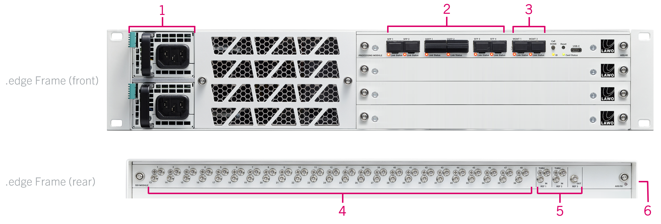
This topic describes all possible connections to the .edge frame. To configure the system, only power (1) and control (3) are required.
Connector Summary

1. Power Inputs: either 2 x AC or 2 x DC - connect power to the frame.
2. Media Network Ports: 4 x 25GbE (via SFP28) and 2 x 100GbE (via QSFP28) - connect the IP streams to the media network.
3. Management Network Ports: 2 x 1GbE (via SFP) - for administration and control.
4. SDI Interfaces: 48 x SDI in/out (via HD-BNC) - connect the SDI signals.
5. Reference Signal Interfaces: 5 x reference in/out (via HD-BNC) - for external synchronization.
6. Functional Earth (M5x12 screw) - to ground the frame.
Front Panel
Power Inputs: AC or DC
The .edge frame can be ordered with either AC or DC power supplies. Only one PSU is required for operation; the second provides redundancy.
- If the frame is specified with AC power supplies, then these are delivered with 2 x IEC power cables that are country-specific.
- To use the DC power supplies option, there are several conditions that must be observed.
Before connecting power to the device, please read and observe all of the important safety information in .edge - Power Supplies.
Media Network Ports
Each processing blade is equipped with eight network interfaces: 6 media and 2 management ports.
While it is possible to connect all six ports, the active ports are determined by the FPGA mode of the processing blade. Options include 25G (only), 100G (only) or 100G + 25G Proxy (all six ports are active).
Please note:
- 25G comes as standard; 100G requires an optional license.
- 25Gbps is fine for SD and HD; 100Gbps is required for 3G and UHD.
- A 100G license is required to support any of the 100G modes. If a 100G license is not available, then the blade runs in 25G (only) mode and the 100G ports are inactive.
The connections are made as follows:
- SFP 1 to 4 - 4 x 25GbE (via SFP28).
- QSFP 1 & 2 - 2 x 100GbE (via QSFP28).
For each stream, you can decide whether it will be transmitted or received via the primary or secondary port. To achieve redundant streaming, you must use both interfaces.
The image below shows the location of the primary and secondary interfaces.

Management Network Ports
- Out-of-band - control data arrives via the MGMT ports: 2 x 1GbE (via SFP). This scheme requires a dedicated management network. To achieve redundant control, you must use both interfaces.
- In-band - control data arrives via the media ports. This scheme can be used if there is no separate management network.
During the initial setup, at least one port must be connected (to configure the blade's network settings).
The ports can then be used to connect the processing blade to a dedicated management network (if you are using out-of-band control). To achieve redundant control, you must use both interfaces.
The connections are made as follows:
- MGMT 1 & 2 – always active: 2 x 1GbE (via SFP).
If you are using in-band control, then the management ports are addressed via the media ports/network (and the physical MGMT ports can be left unconnected).
Using the Network Interfaces
To use the network ports, you must fit the correct optical transceivers. These must be Lawo-certified (as described earlier). The optical transceiver determines the cable type, maximum distance and connector.
| Link Status LED | Meaning | Recommended Actions | |
|---|---|---|---|
Green | Link up (ok). | No action required. | |
Yellow | Link down: optical transceiver detected but no connection. | Check the connection to the network switch. | |
Off | Link down: optical transceiver missing. | Check the fitting of the optical transceiver. | |
Rear Panel
SDI Interfaces
Each rear I/O plate is equipped with 48 x HD-BNC for SDI interfacing.
The number of available SDIs is determined by the number of ".edge_sdi" licenses on the processing blade. In addition, the number of SDI inputs versus outputs can be changed using the Device Options (in HOME's General tab).
For all possible configurations, see .edge - Rear I/O Plates.
Reference Signal Interfaces
- The two reference inputs can be used to connect up to two external sync reference signals. In each case, the THRU connector provides a "looped-through" output of the corresponding IN.
- The REF OUT is always active and provides an output of the current reference: External IN 1, External IN 2, PTP or Internal (free-run).
The current reference can be changed using the HOME Web UI. For more information, see .edge - Synchronization.
Functional Earth
The M5x12 grounding screw must be used to ground the frame for EMC reasons.
The grounding screw can be found on the right side of the frame (when viewed from the rear).
See .edge - Grounding.