.edge - Rear I/O Plates
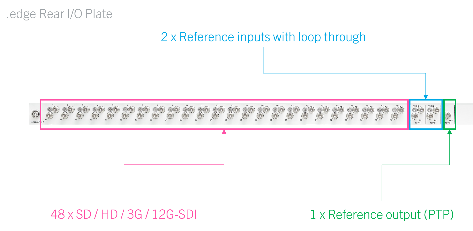
At the rear of the frame are the I/O plates (up to 4 per frame). Each plate is equipped with 48 x HD-BNC (for SDI interfacing) + 5 x HD-BNC (for external synchronization).
The rear I/O plates are hot-pluggable and so it is possible to add or replace a plate while the frame is powered. See Fitting a Rear I/O Plate for instructions.
SDI Interfacing
Each rear I/O plate is equipped with 48 x HD-BNC for SDI interfacing, where the number of available SDIs is determined by the active SDI licenses on the processing blade.
Available SDIs
When a processing blade is ordered using the ".edge_gateway" part number, it comes with a rear I/O plate and a single ".edge_sdi_inc" license (to enable 16 SDI interfaces). This can be expanded by adding either one or two ".edge_sdi" licenses (to enable 32 or 48 SDI interfaces). Thus, there are three licensing options for each blade:
- Base system (1 x .edge_sdi_inc license is included) = 16 x SDI.
- Option 1 (adds 1 x .edge_sdi license) = 32 x SDI.
- Option 2 (adds 2 x .edge_sdi licenses) = 48 x SDI.
SDI I/O Configurations
For each licensing option, the user can choose one of three SDI I/O configurations to determine the number of SDI inputs and outputs.
This provides nine possible configurations for each blade/plate:
- Base system (16 x SDI)
- Preset 1 = 8 in + 8 out
- Preset 2 = 4 in + 12 out
- Preset 3 = 12 in + 4 out
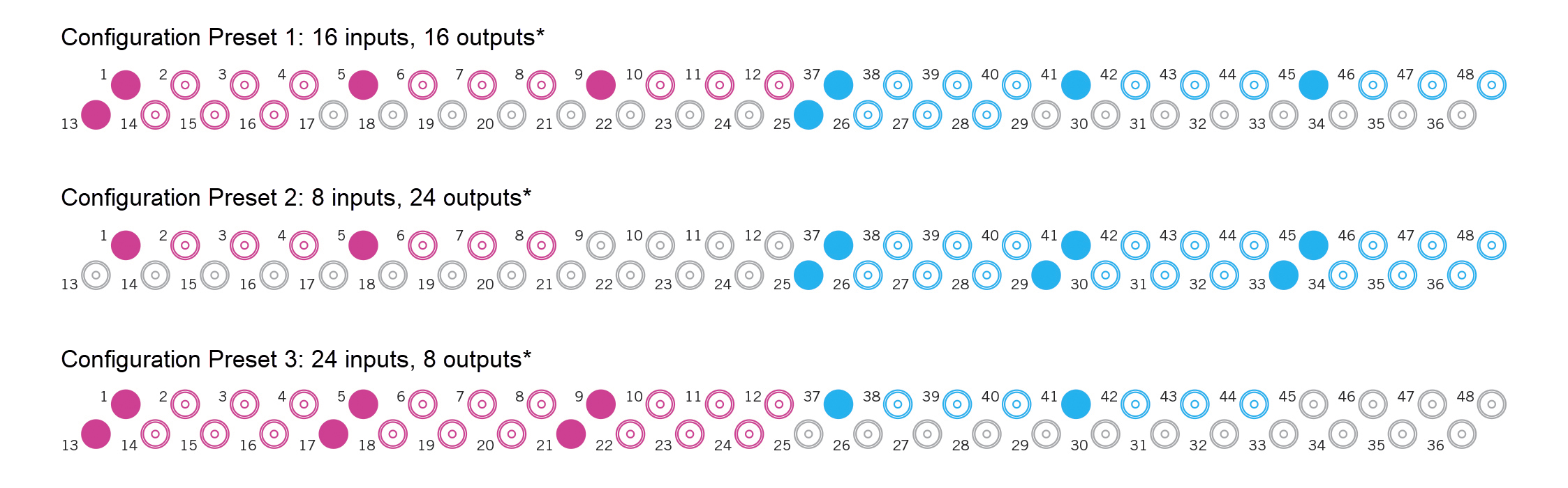
- Option 1 (32 x SDI)
- Preset 1 = 16 in + 16 out
- Preset 2 = 8 in + 24 out
- Preset 3 = 24 in + 8 out
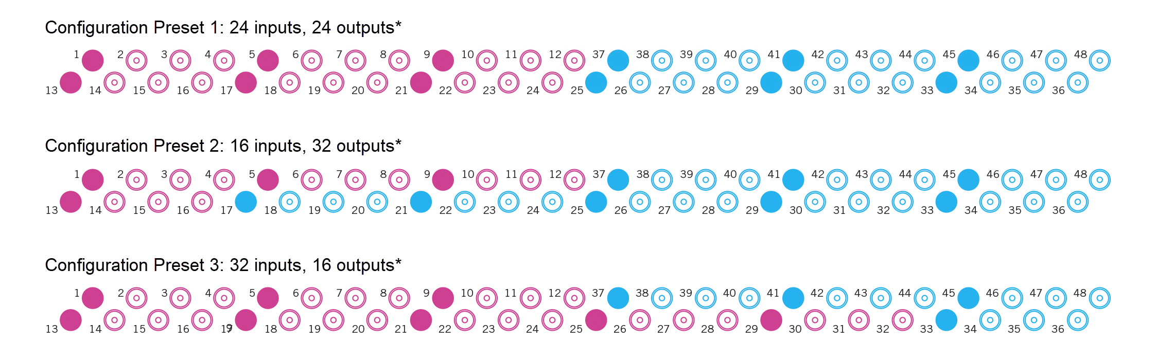
- Option 2 (48 x SDI)
- Preset 1 = 24 in + 24 out
- Preset 2 = 16 in + 32 out
- Preset 3 = 32 in + 16 out
12G-Capable SDIs
While all connectors provide full support for SD, HD, 3G and 12G signals, the number of simultaneous 12G streams is defined by the bandwidth of the network interfaces. This means that, in the current release, there is a limit on the number of 12G-capable SDI inputs and outputs:
- Base system: up to 4 x 12G-SDI.
- Option 1 license: up to 8 x 12G-SDI.
- Option 2 license: up to 12 x 12G-SDI.
The 12G- capable inputs and outputs are indicated by a solid connector in the connectivity diagrams below. To connect a 12G-SDI signal, there are two possibilities:
- Connect a single-link 12G-SDI signal to a solid connector (1, 5, 9, etc.) and leave the other three connectors in the block unused.
- Or, if using 3G UHD gearboxing, connect the 4 x 3G-SDI signals to a quad-link block: 1-4, 5-8, 9-12, etc. This option requires a ".edge_gbox" license for each quad-link instance.
In both cases, if you wish to add input frame synchronization, you will need to purchase 4 x input frame sync licenses for each 12G instance.
Connectivity
The table below describes the rear I/O plate connectivity for each license option and configuration preset.
| SDI Interfacing Bundle | Active Licenses (on Blade) | Available SDIs (on Rear I/O) | SDI in/out option (for Rear I/O) |
|---|---|---|---|
Base system | 1 x .edge_sdi | 16 x SDI |
|
| Option 1 (adds 1 x .edge_sdi license) | 2 x .edge_sdi | 32 x SDI |
|
| Option 2 (adds 2 x .edge_sdi licenses) | 3 x .edge_sdi | 48 x SDI |
|
*Solid connectors indicate 12G-capable inputs and outputs. |
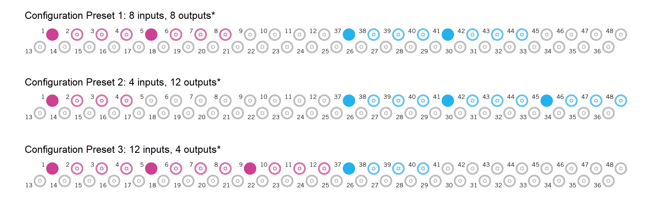
A: On each rear I/O plate, the top row of connectors is directional and the bottom row is bi-directional. This means that, for example, the thirteenth connector on the top row can only ever operate as an SDI output.
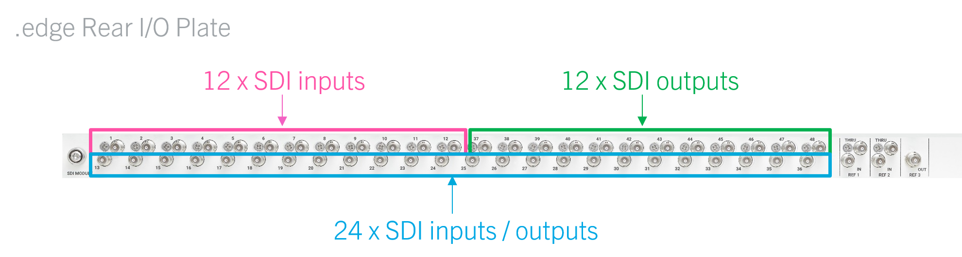
The numbering scheme has been chosen so that all of the SDI inputs (1 to x) are followed by all of the SDI outputs (y to 48), regardless of the configuration preset.
For external wiring purposes, it is useful to know that...
- Connectors 1 to 12 are always SDI inputs.
- Connectors 37 to 48 are always SDI outputs.
- For the remaining connectors (13 to 36), the direction is software-defined (by the configuration preset). The possible options are shown in the table above.
Cabling
Before cabling the connectors, please read the following important safety information.
![]() (E) WARNING
(E) WARNING
Section 5.7.7 of IEC 62368 (Ed. 2) specifies that a device must be connected to an additional fixed protective ground if it is conductively connected with more than 20 other devices. e.g. has more than 20 copper I/O connections.
For more information, see .edge - Grounding.
![]() (F) AVERTISSEMENT
(F) AVERTISSEMENT
La section 5.7.7 de la norme CEI 62368 (Ed. 2) spécifie qu'un dispositif doit être connecté à une terre de protection fixe supplémentaire s'il est connecté de manière conductrice avec plus de 20 autres dispositifs, par exemple s'il possède plus de 20 connexions E/S en cuivre.
Pour plus d'informations, voir .edge - Mise à la terre.
Reference Inputs and Outputs
- The two reference inputs can be used to connect up to two external sync reference signals. In each case, the THRU connector provides a "looped-through" output of the corresponding IN.
- The REF OUT is always active and provides an output of the current reference: External IN 1, External IN 2, PTP or Internal (free-run).
The current reference can be changed using the HOME Web UI. For more information, see .edge - Synchronization.
Ordering Information
A rear I/O plate can be ordered using the part numbers .edge_gateway (for a complete SDI I/O package) or A00/50-11 (for a replacement I/O plate). See .edge - Ordering Information.
Specifications
For information about the SDI and reference standards, supported formats, return loss and cable lengths, see .edge - Technical Specification.