.edge - Replacing a Rear I/O Plate
The following procedure can be used to fit or exchange a rear I/O plate.
Overview
Each .edge frame can be fitted with up to 4 x I/O plates (fitted to the rear).
The rear I/O plates are hot-pluggable and so it is possible to add or replace a plate while the frame is powered.
What you will need
- 1 x Torx10 driver - included in the Lawo toolkit supplied with the system.
- 1 x HD-BNC removal tool - included in the Lawo toolkit.
- 1 x .edge rear I/O plate - ordered using the part numbers .edge_gateway (for a complete SDI I/O package) or A00/50 (for a replacement I/O plate).
- 1 x .edge rear slot blanking panel - if you wish to operate the frame without an I/O plate. This can be ordered using the part number: .edge_frame_blind_plate_rear.
Instructions
Please read the following important safety information and then follow the step-by-step instructions.
![]() (E) WARNING
(E) WARNING
Please read and observe ALL of the Lawo Products - Important Safety Instructions BEFORE installing or servicing any component.
![]() (F) AVERTISSEMENT
(F) AVERTISSEMENT
Veuillez lire et respecter TOUTES les consignes de sécurité importantes AVANT d’installer ou d’entretenir un composant.
![]() (E) CAUTION
(E) CAUTION
If a frame is not fully populated, then any spare slots must be closed with blanking panels. For safety reasons and to ensure efficient cooling, the frame must not be operated with an empty slot.
![]() (F) ATTENTION
(F) ATTENTION
Si un cadre n'est pas entièrement rempli, les emplacements libres doivent être fermés par des panneaux d'obturation. Pour des raisons de sécurité et pour assurer un refroidissement efficace, le cadre ne doit pas être utilisé avec un emplacement vide.
1. Remove the existing I/O plate (or blanking panel).
- Disconnect and remove all of the SDI and Reference cables. It is recommended to use the HD-BNC removal tool (included in the Lawo toolkit).
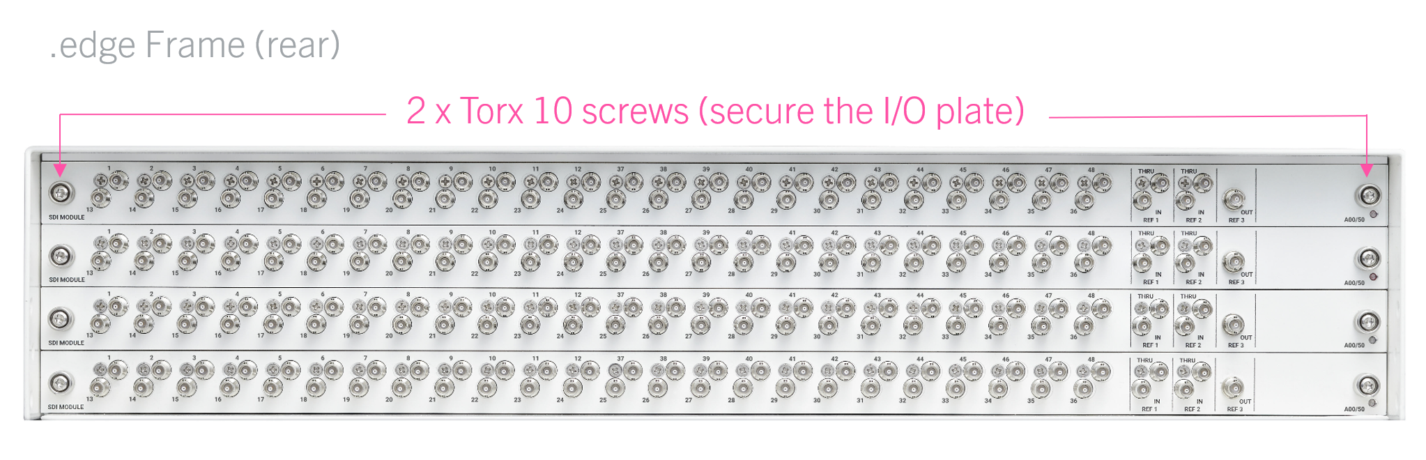
- Using a Torx10 driver, remove the two securing screws at each side of the plate (or blanking panel). The screws should be loosened alternately so that the I/O plate slides smoothly out of the frame. If you loosen one screw completely, then this may cause damage to the plate or frame.
- Carefully, remove the I/O plate (or blanking panel) from the rear of the frame.
- Store any blanking panels safely (as they may be required in the future to close the frame).
2. Fit the new I/O plate (or blanking panel).
- Take the I/O plate out of its packaging and slide it carefully into the guide rails (at the rear of the frame).
- Secure by tightening the 2 x Torx10 screws. The screws should be tightened alternately so that the I/O plate fits smoothly into the frame. If you tighten one screw completely, then you may cause damage to the plate or frame.
- A blanking panel can be fitted in a similar manner. Each panel includes a metal divider (behind the fascia) that is important for the airflow.
3. Reconnect the SDI and Reference port cables and test the operation of the I/O.