.edge - Power Supplies
Each .edge frame is powered by two power supplies (fitted to the front). Only one PSU is required for operation; the second provides redundancy.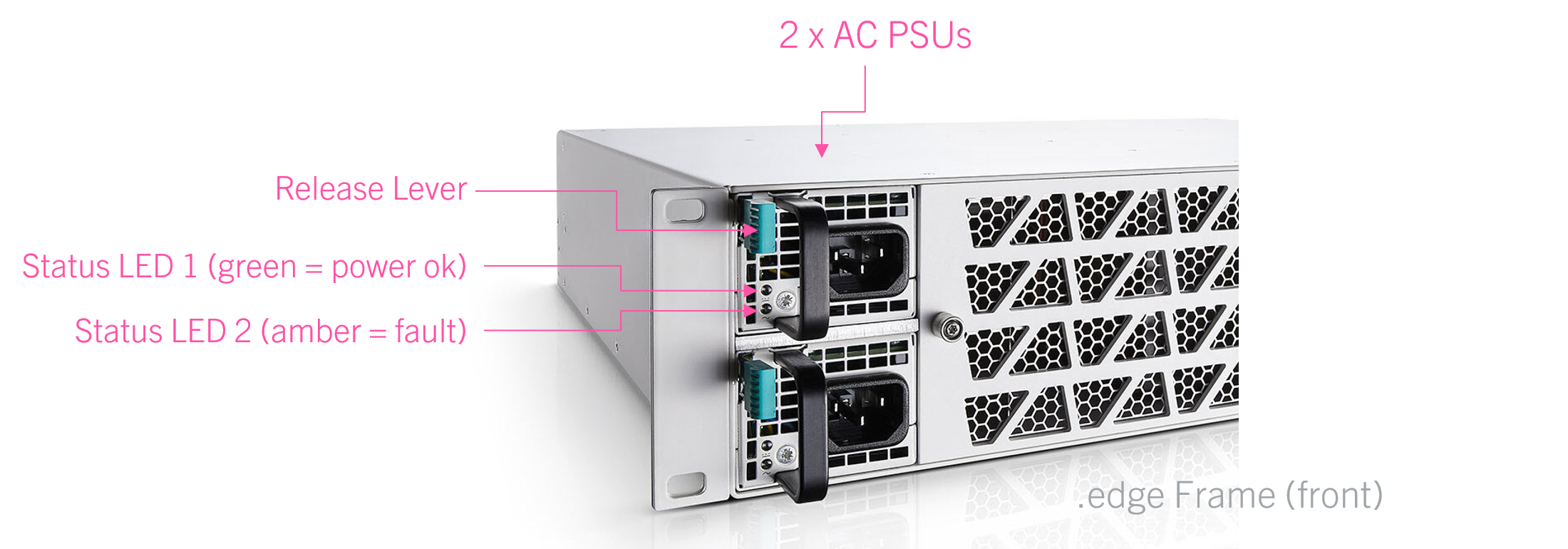
The PSUs are hot-pluggable and so it is possible to replace the redundant unit while the device is powered. See Replacing a Power Supply Unit for instructions.
Power Supply Options
.edge can be ordered with either AC or DC power supplies. To use the DC power supplies option, there are several conditions that must be observed (described below).
It is important that the frame is fitted with two identical power supplies: of the same type and from the same manufacturer. This happens automatically when you order a frame variant. However, for spare parts, you must take care that the replacement unit is a match.
Permitted AC Power Supplies:
- 2 x 436-9918-000 (black) or 436-9919-000 (white) - D1U54P-W-1200-12-HC3 series.
Note that the AC power supplies come in a choice of front grill colors (e.g. 436-9918-000 is black and 436-9919-000 is white). The two colors can be mixed and so it is ok to fit a frame with 1 x 436-9918-000 (black) + 1 x 436-9919-000 (white).
Permitted DC Power Supplies:
- 2 x 436-9920-000 - D1U54-D-1200-12-HC3PC.
Ordering Information
For a new system, the power supplies are included in the frame variant. See .edge - Ordering Information.
To order a spare part, please use the part numbers listed above.
Electrical Specification
For input voltages and power consumption, see .edge - Technical Specification.
IEC Power Cables
If the frame is specified with AC power supplies, then these are delivered with 2 x IEC power cables that are country-specific. The table below describes all permitted options.
| Name | Part Number | Description | |
|---|---|---|---|
IEC Lock Schuko | 436-7206-000 | Power Cord with European connector for e.g. D, AU, F, Benelux. | |
IEC Lock Open Ends | 436-7207-000 | Power Cord with open wire ends. | |
IEC Lock US | 436-7208-000 | Power Cord with connector for USA. | |
IEC Lock UK | 436-7209-000 | Power Cord with connector for United Kingdom. | |
IEC Lock AUS | 436-7218-000 | Power Cord with connector for Australia. | |
IEC Lock JPN | 436-7219-000 | Power Cord with connector for Japan. | |
Using the AC Power Supplies
Before connecting power to the frame, please read and observe all of the instructions in the "General Safety Information for Lawo Equipment" booklet delivered with your devices.
![]() (E) WARNING
(E) WARNING
The AC input(s) MUST be connected to the mains using the power cable(s) supplied with the system.
Disconnect all power sources to completely disconnect power from the system. e.g. before you open the unit for maintenance and service.
Take care that the protective earth (PE) connection of each PSU is individually connected to the PE connection of the building installation (e.g. wall socket). It is forbidden to use IEC Y-cables, or connect both PSUs to the same multiple-socket outlet. This measure guarantees that there is no shared PE connection (whose failure would lead to a summation of the leakage current from both PSUs to the housing).
![]() (F) AVERTISSEMENT
(F) AVERTISSEMENT
La ou les entrées CA DOIVENT être connectées au secteur à l'aide du ou des câbles d'alimentation fournis avec le système.
Déconnectez toutes les sources d'alimentation pour couper complètement l'alimentation du système, par exemple avant d'ouvrir l'unité pour la maintenance et l'entretien.
Veillez à ce que la connexion de terre de protection (PE) de chaque PSU soit connectée individuellement à la connexion PE de l'installation du bâtiment (par exemple, une prise murale). Il est interdit d'utiliser des câbles en Y IEC, ou de connecter les deux PSU à la même prise multiple. Cette mesure garantit qu'il n'y a pas de connexion PE partagée (dont la défaillance entraînerait une sommation du courant de fuite des deux PSU vers le boîtier).
Powering On
- You will hear the fans speed up when power is first applied. This is normal. The fan speed will settle once the operating temperatures of all processing blades have been determined (by the master blade).
- The processing blades take approximately 40 seconds to boot from power on.
- At the end of the boot-up, each processing blade loads the latest settings (stored at shut-down).
PSU Status LEDs
- LED 1 (power) - lights in green when the power is ok.
- LED 2 (fault) - lights in amber if there is a fault or warning.
The table below describes all possible states.
| PSU LED | Condition(s) | Meaning | Recommended Actions |
|---|---|---|---|
1 - Off | No power. | No AC (or DC) input. | Check the AC mains supply and IEC connection. |
1 - Green (blinking) | Standby ON; Main output OFF; AC (or DC) present. | AC (or DC) input detected; PSU is starting. | Wait for PSU to start. |
1 - Green (solid) | Standby ON; Main output ON. No errors detected. | PSU is active; no errors. | Normal operation; no action required. |
2 - Amber (solid) | Main output overcurrent, undervoltage or overvoltage. | Internal fault. | Check the PSU Health pages (in HOME's Advanced parameters). |
2 - Amber (blinking) | Power supply warning event triggered. | Internal warning. |
Installing a Frame with DC Power Supplies
To use the DC power supplies option, there are several conditions that must be observed:
- The use of DC power supplies is only permitted if your system is installed in an area with restricted access (to skilled persons only).
- The device with its PSU and the complete DC mains power distribution system must be placed entirely within a single building.
- The ground (PE) terminal of the .edge frame must be connected to the ground (PE) of the DC mains power distribution system.
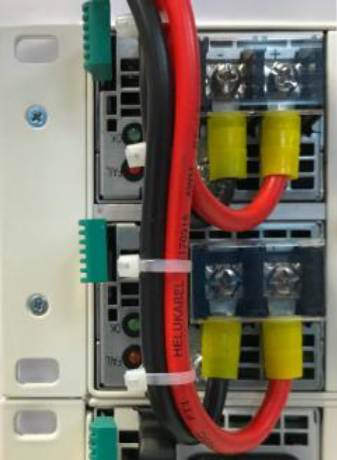
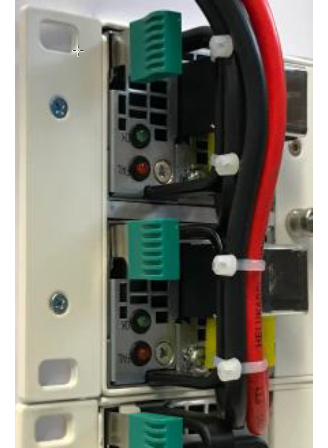
- It is mandatory to install some means of cable strain relief for the wires that feed each PSU.
- For example, by installing a clamp on a 19-inch panel mounted above the .edge frame.
- Or, if this is not possible, by fixing the wires to the PSU handles using some cable ties (as shown below).
- The cable strain relief will need to be removed and replaced if you need to exchange a PSU.
| Example of Cable Strain Relief (for DC PSUs) | |
front view 1
| front view 2 |
- A 48V DC mains power distribution system feeding the PSU must be classified as a “SELV” (according to 60950) or as “ES1” (according to 62368).
- A 60V DC mains power distribution system feeding the PSU must be classified as a “SELV/TNV-2” (according to 60950) or as “ES2” (according to 62368).
- Please observe the maximum working voltage (described in the table below).
| Maximum Working Voltage | ||
|---|---|---|
| DC PSU Input | Earth | 72Vrms |
| DC PSU Output | Internal circuits of .edge | 72Vrms, 93Vpeak |
The branch circuit protection feeding the PSU must be protected by a fuse or circuit breaker rated with 100A maximum. We recommend using an 80 A protection device.
The breaking capacity must fit the requirements of the DC mains power distribution system.
The wires that feed the DC PSU must offer a cable cross-section at least of AWG 10 (5,2 mm²). Please check whether a higher cable cross-section is required (based on the local standards and installation situation).
Use stranded wire with ring or fork terminals.
Take care that if a strand of a conductor should escape, it does not make contact with any other part of the device.
- A disconnect device must be provided between the DC mains power distribution system and the PSU.
- The disconnect device must be rated for the DC voltage of the DC mains power distribution system and must provide sufficient clearance and creepage distances.
- The DC mains power must be disconnected from the device, using the disconnect device, before the feeding wires are disconnected at the DC PSU.
- The input terminal block has not been evaluated for current interruption purposes.
- If one of the PSU slots is not in use, then make sure that the wires of the DC mains are either isolated (isolated Splicing Connector, isolation tape or tube) or that the disconnect device is secured in the OFF position (lock, marking and cable tie).
![]() (E) WARNING
(E) WARNING
Disconnecting the feeding wires to the DC PSU while voltage is present can result in a harmful electric arc.
![]() (F) AVERTISSEMENT
(F) AVERTISSEMENT
Le débranchement des fils d'alimentation du bloc d'alimentation DC pendant la tension est présente peut provoquer un arc électrique dangereux.
Once the installation is complete, the frame should be powered on (and off) using the disconnect device. The PSU status can be checked using the two LEDs at the front (described earlier).