.edge - Installing the Frame
.edge is designed for indoor use in a dust-free environment. The frame should be mounted, horizontally, in a 19-inch equipment rack (as described below).
Before mounting the frame, it is important to understand how the device is cooled to ensure that the final installation meets the airflow requirements.
For dimensions, weight and power, see .edge - Technical Specification.
If the frame is fitted with DC power supplies, then you must observe all of the DC power supply conditions (described earlier).
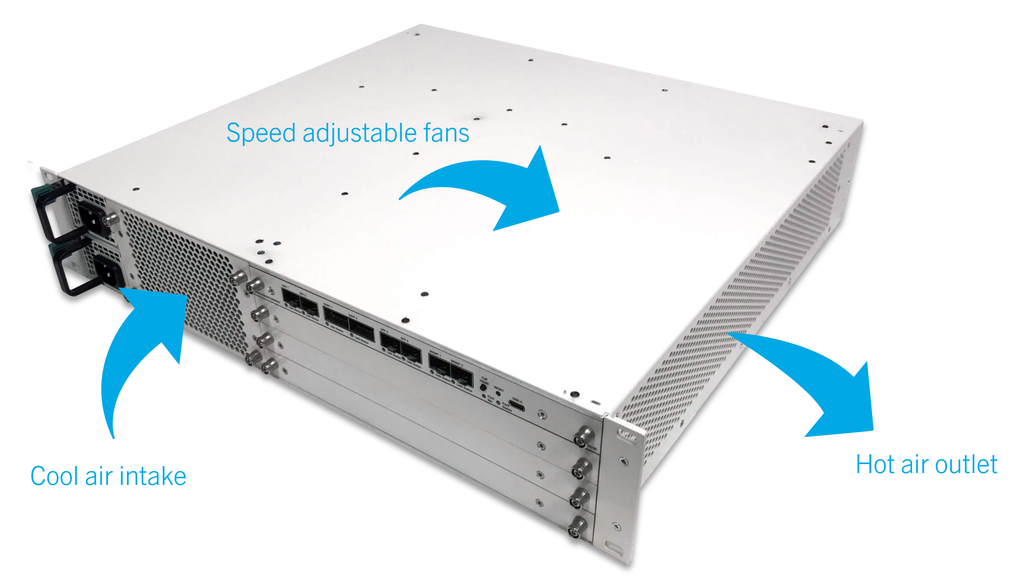
Airflow Requirements
.edge is cooled by five temperature-controlled fans (fitted behind the front grill).
![]() (E) ATTENTION
(E) ATTENTION
- DO NOT obstruct the ventilation holes as to do so will prevent efficient cooling.
- If the maximum operating temperature of +30°C (+86°F) is exceeded, then the power to the processing blades is cut (to prevent damage to the FPGAs due to overheating). In this instance, all operations will stop until the unit has reached a safe temperature.
![]() (F) ATTENTION
(F) ATTENTION
- N'obstruez PAS les trous de ventilation, car cela empêcherait un refroidissement efficace.
- Si la température maximale de fonctionnement de +30°C (+86°F) est dépassée, l'alimentation des lames de traitement est coupée (pour éviter d'endommager les FPGA en raison d'une surchauffe). Dans ce cas, toutes les opérations s'arrêteront jusqu'à ce que l'unité ait atteint une température sûre.
Rack Requirements
To support the weight of the device, the frame must be attached to the equipment rack at both the front and rear. This is achieved as follows.
- The front of the frame attaches to the front of the rack using the mounting screws provided.
- At the rear, the frame must be fitted with a rack-mounting kit (as described below).
Connectors are located at the front and rear of the unit. Therefore, when using 19-inch racks with doors please leave enough room for the cables (and airflow).
Due to the position of the ventilation holes, it is ok to install other rack-mounted units either directly above or below the .edge frame.
Installing the Processing Blades and I/O Plates
As standard, the frame is delivered with blanking panels to close the front and rear slots. Therefore, before mounting the frame, you must fit the processing blades and rear I/O plates.
How to do this is described later. See Fitting a Processing Blade and Fitting a Rear I/O Plate.
Mounting Instructions
To mount the frame, please read the following important safety information and then follow the step-by-step instructions.
![]() (E) WARNING
(E) WARNING
Please read and observe ALL of the Important Safety Instructions BEFORE installing the frame.
![]() (F) AVERTISSEMENT
(F) AVERTISSEMENT
Veuillez lire et respecter TOUTES les consignes de sécurité importantes AVANT d'installer le cadre.
![]() (E) CAUTION
(E) CAUTION
- The frame must be installed using one of the rear rack-mounting kits provided (to support the weight of the device).
- DO NOT install the frame into a rack with slide rails (as to do so will block the hot air outlet and prevent efficient cooling).
- Leave enough space at the front of the frame (for the connectors, cables and cold air intake).
- Leave enough space at the rear of the frame (for the connectors and cables).
- Leave enough space at the right side of the frame (for the hot air outlet).
- DO NOT block the front or side ventilation holes.
![]() (F) ATTENTION
(F) ATTENTION
- Le châssis doit être installé à l'aide de l'un des kits de montage en rack arrière fournis (pour supporter le poids de l'appareil).
- NE PAS installer le châssis dans un rack avec des glissières (car cela bloquerait la sortie d'air chaud et empêcherait un refroidissement efficace).
- Laissez suffisamment d'espace à l'avant du cadre (pour les connecteurs, les câbles et la prise d'air froid).
- Laissez suffisamment d'espace à l'arrière du cadre (pour les connecteurs et les câbles).
- Laissez suffisamment d'espace sur le côté droit du cadre (pour la sortie d'air chaud).
- N'obstruez PAS les orifices de ventilation frontaux ou latéraux.
1. Start by fitting the rack-mounting kit to the rear of the .edge frame.
There are two kits available to support different rack depths. The kit supplied with your frame is specified at the time of order (as part of the frame variant). If you need to order a different kit, then please use the Accessory part numbers listed in .edge - Ordering Information.
The mechanical drawings below show the parts supplied for each option.
| Rack-mounting Kit | Mechanical Drawings | |
|---|---|---|
| .edge frame rack-mounting kit (600mm) | A00_10_57_00_Rack mounting rear kit 600mm.pdf | |
| .edge frame rack-mounting kit (800-900mm) | A00_10_58_00_Rack mounting rear kit 800-900mm.pdf | |
Each kit contains:
- 2 x rack-mounting brackets/rails with ears - to span the gap between the rack and frame.
- 6 x screws (M3x4) - to secure the brackets to the frame.
Using the screws provided, fix the brackets to the rear of the frame. There are six screws in total: three for each bracket.
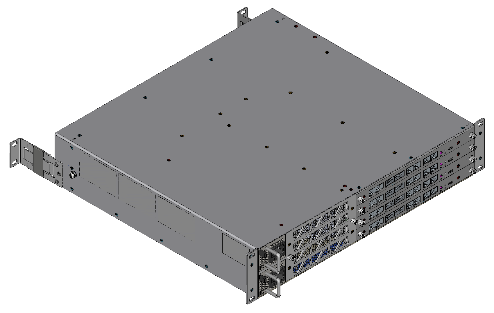
The image below shows the final assembly when using the shorter (600mm) rack-mounting rails.
2. Fix the front of the frame to the rack using the mounting screws provided.
There are four holes/screws in total: two for each side of the unit.
3. Fix the rear rack-mounting brackets to the rack using the mounting screws provided.
There are four holes/screws in total: two for each bracket.
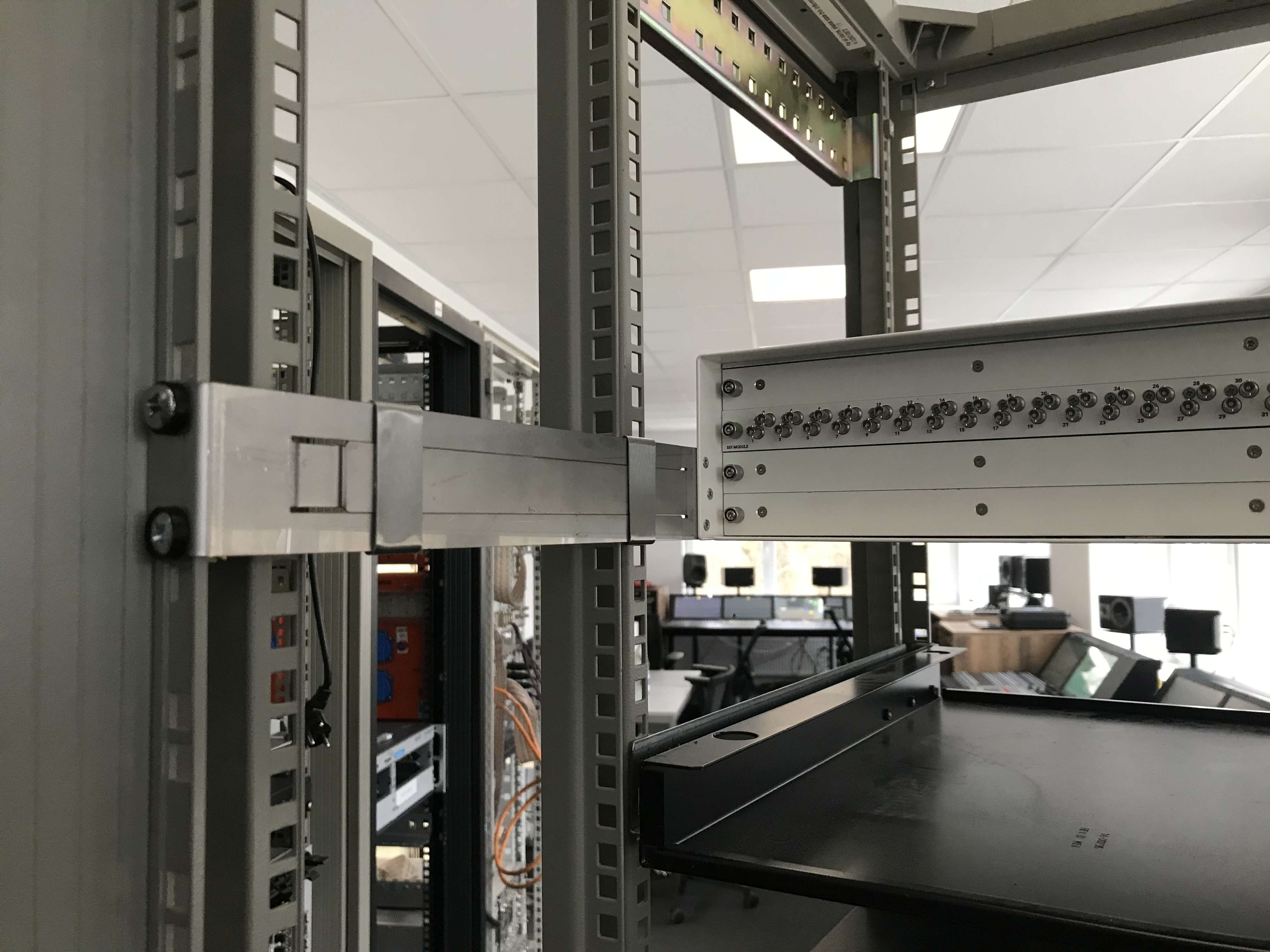
The image below shows how one side of the rear installation should look when using the longer (800-900mm) rack-mounting rails.