diamond - Fader Strip Control
Any fader strip can control any type of source and, depending on the configuration, supports layer switching and fader mapping. This enables lots of signals to be controlled by very few physical faders.
diamond supports two different layouts for its fader strip controls: either Fader A or Fader B. In each case, it is only the physical layout that differs; there is no difference in the operation.
If the frame includes a Rotary Fader Extension module, then this adds 4 extra rotary controls to the fader strip. The operation of these controls is described later. See Working with Extension Modules.
Controls Overview
Each fader strip is divided into the following areas.
Fader A |
Fader B |
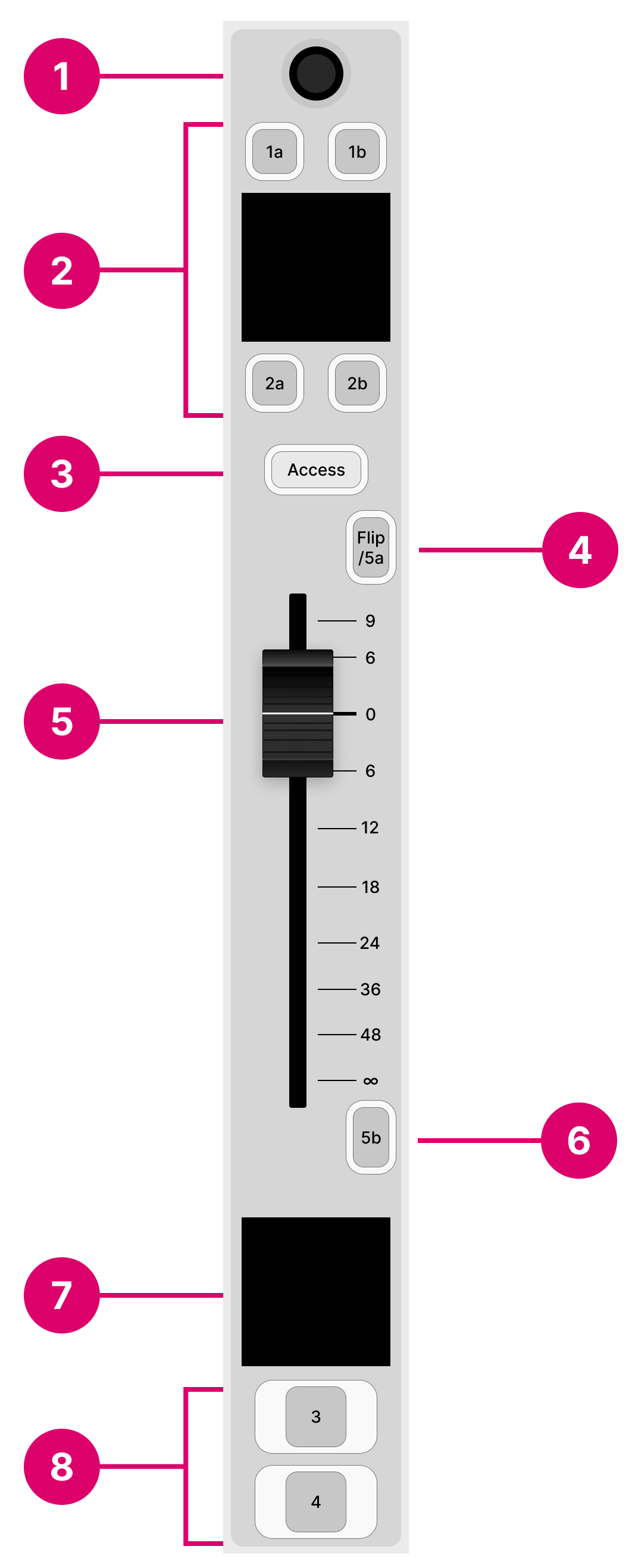
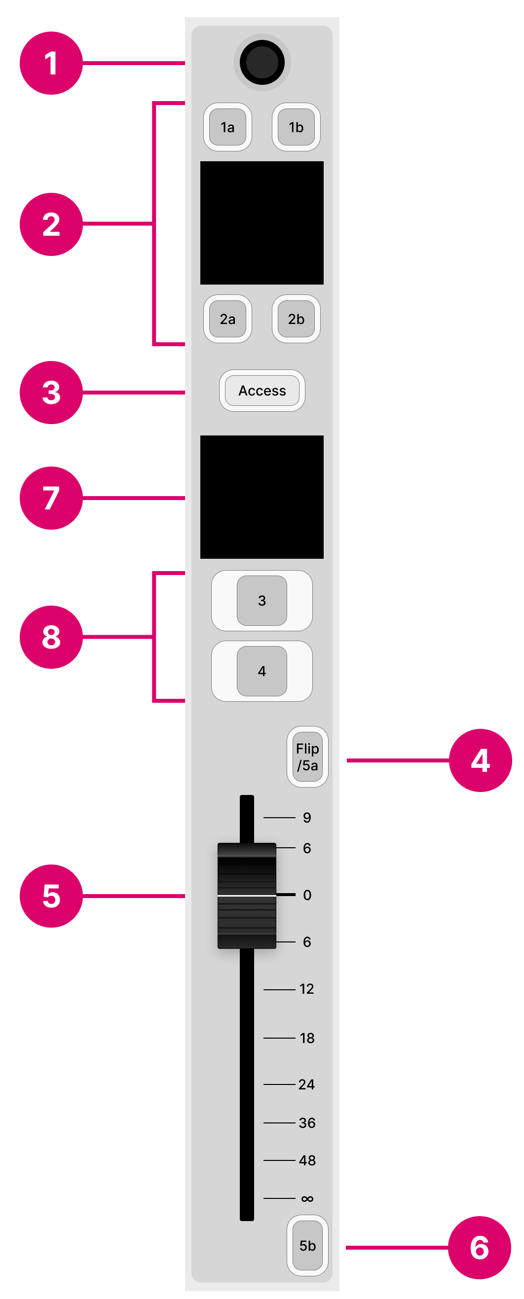
The operation of the following controls is system-defined: rotary control (1), Access key (3), Flip key (4), fader (5) and source display (7). The MF keys (2, 6 and 8) are defined by the configuration. The Flip key (4) can be configured as another MF key if layer switching is disabled.
There are no differences in operation between the Fader A and B modules.
Operation
Rotary Control
The rotary control at the top of the fader strip adjusts the microphone gain, channel input gain and pan (plus stream selection for Ravenna sources). The operation is system-defined and provides the same fixed functionality regardless of the configuration.
Press down on the rotary control to step through the available parameters and turn to adjust the current value. The parameter name and value appear briefly in the display.
The available parameters vary depending on the type of source. See Input Gain & Pan and Stream Selection.
MF Keys 1a, 1b, 2a, & 2b
The four small MF keys are labelled by the display. They are programmed by the configuration and are defined per source. Typical functions include Conf (Conference), AMix (Automix) and AGn (Auto Gain).
Access Key
The Access key is used to select a source (for parameter control) or activate strip assign mode. These operations are system-defined and provide the same fixed functionality regardless of the configuration.
The key has four possible states. The colors used can be modified by the ON-AIR Designer (under "System → Definition → Colors"). The following colors are used in the standard configuration:
- Off (unlit) = there is no source assigned to the fader strip.
- Dim white = a source is assigned to the fader strip but is not in access.
- Full white = a source is assigned to the fader strip and is selected (for source parameter control).
- Full yellow = the fader strip is in source assign mode.
The operation is as follows.
Press Access once (full white) to place the source in access. The Source Parameter Control keys in the centre section update accordingly and the 'Source Parameter' dialog box appears on the GUI. For more details, see Source Parameters.
Press Access twice in quick succession (full yellow) to activate strip assign mode. The 'Assign Source' dialog box appears on the GUI. From here you can touch an available source to make an assignment. Alternatively, turn the fader strip rotary control (1) to select a source and then press the Take key (2). For more details, see Fader Strip Assign.
Flip (or MF Key 5a)
By default, this key is labeled Flip and is used to switch the fader strip between its two layers.
The key has two possible states. The colors used can be modified by the ON-AIR Designer (under "System → Definition → Colors"). The following colors are used in the standard configuration:
- Dim white = layer switching is off, Layer 1 is in view.
- Full green = layer switching is on, Layer 2 is in view.
The layers can also be flipped globally using the Layer key in the centre section. Note that the global Layer key resets any individual Flip selections.
If Layer 2 is disabled by the configuration, then the same physical key operates as MF Key 5a. In this instance, there is no layer switching and the key can be configured to perform a different function using the ON-AIR Designer.
Layer 2 can be disabled, individually, for each Fader or Combo Module (under "Surface → Fader Module → Source"). Thus, it is possible to have some modules with two layers and others with one layer. In this instance, the global Layer key flips all modules with Layer 2 enabled.
Fader
The fader adjusts the channel level from -∞ to +9dB.
The fader is motorized and touch-sensitive. It also has a notch that is set to 0dB and an overpress function that is triggered when you pull back on the fader.
The notch and overpress can be enabled or disabled, by the operator, from the Setup menu.
The overpress function is programmed by the configuration and is defined globally for all fader strips. In the standard configuration, it triggers PFL (pre-fader listen).
MF Key 5b
This MF key is programmed by the configuration and is defined per source. Typically, it provides talkback to sources such as Mics and Codecs.
Source Display
This display always shows the name of the source controlled by the fader strip, its input level and color.
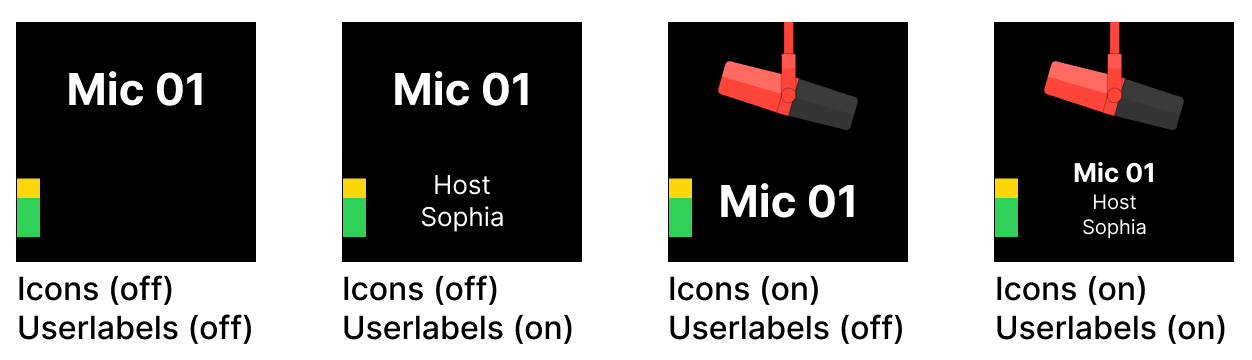
In the standard configuration, the following options can be enabled or disabled from the 'Settings → Surface' dialog box (on the GUI):
- Show Icons in Fader Displays - shows the icon assigned to the source.
- Show Userlabels - shows the two user label lines. The text can be edited by opening the user labels editor.
The images below show the four possible states of the 'Source Display'.
For Ravenna sources, the two user label lines show the Group and Stream name of the incoming stream. If a streaming connection is in progress, then you will see its status: pending, tuning, etc.
The source name, icon and color can be edited using the ON-AIR Designer (under "Sources → Source Parm"):
Source Name = the "Display Name" field.
Source Color = the "Source Color" field.
Source Icon = the " Source Icon" field.
MF Keys 3 & 4
The two large MF keys are programmed by the configuration and are defined per source. Typically, they are used to turn the channel ON and activate PFL (pre-fader listen).