HOME DSK - Advanced -> Senders
The Advanced → Senders menu provides information and configuration controls for the app's media network senders.
There is a main page with global parameters, plus a sub-page for each available sender.
For a HOME DSK, there are two senders that correspond to the app's outputs as follows:
- TX 1 = Program output
- TX 2 = Preview output
The senders can be viewed and configured separately.
Please note: The sender sub-pages, and their controls, are dependent on the output transport type defined in the app configuration. i.e. ST 2110-xx, SRT, WebRTC or NDI.
This topic describes the Advanced menu controls for all possible sender types, plus the Tally controls (supported by all senders).
Senders
The main 'Senders' menu contains a single control that applies to all configured senders.
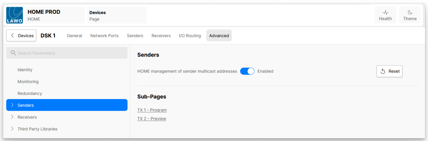
| HOME management of sender multicast addresses | This option defines how the multicast addresses (for the senders) are assigned, when they are first created:
Please note: The multicast address can be overridden from the 'Edit Sender' dialog. See HOME Apps - Edit Sender or Receiver. |
Senders → TX n
The 'TX 1 - Program' and 'TX 2 - Preview' sub-menus can be used to view and adjust settings for an individual sender.
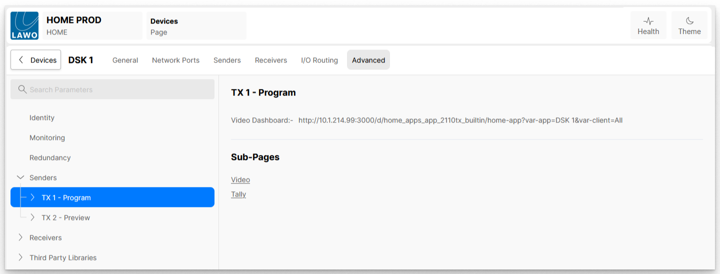
In each case, there is a link to a predefined Grafana Dashboard that can be used for monitoring purposes, plus a number of further sub-pages.
The first few sub-pages, and their controls, are dependent on the output transport type defined (by the user) in the app configuration:
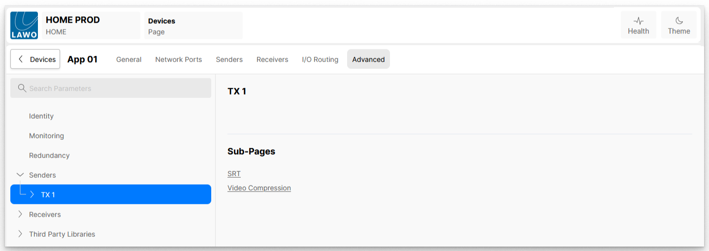
- for ST 2110-xx senders, there is a sub-menu for each available flow: Video and Audio (for Background A and B); Video only (for Key n and Fill n). If ST 2110-22 (JPEG-XS) is specified, then there is an additional sub-menu for the Video Compression settings.
- for SRT senders, the media stream sub-menus are replaced with SRT and Video Compression settings.
- for WebRTC senders, the media stream sub-menus are replaced with RTP and Video Compression settings.
- for NDI senders, there are no available controls.
The Tally sub-page provides access to the 8 Tally User Bits. These are supported by all sender types.
The rest of this topic describes the possible sub-menus for each transport type plus the Tally controls.
ST 2110-20 or ST 2110-22 (JPEG-XS) Senders
When the app's output video transport is set to either ST 2110-20 or ST 2110-22, the sender's sub-pages can be used to access the SDP information for the individual flows: Video, Audio1, etc.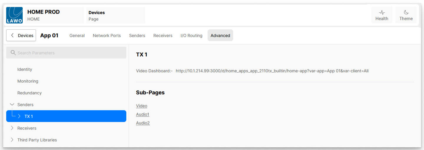
SDP Information
Selecting a sub-page (e.g. Video) reveals the SDP file associated with that sender. The user is not able to modify the SDP, but can copy the SDP information. This can then be pasted into the SDP Data of a receiver as an alternative method of routing signals (known as SDP Patching).
The SDP file information is also available to automation systems, such as VSM, via the HOME API.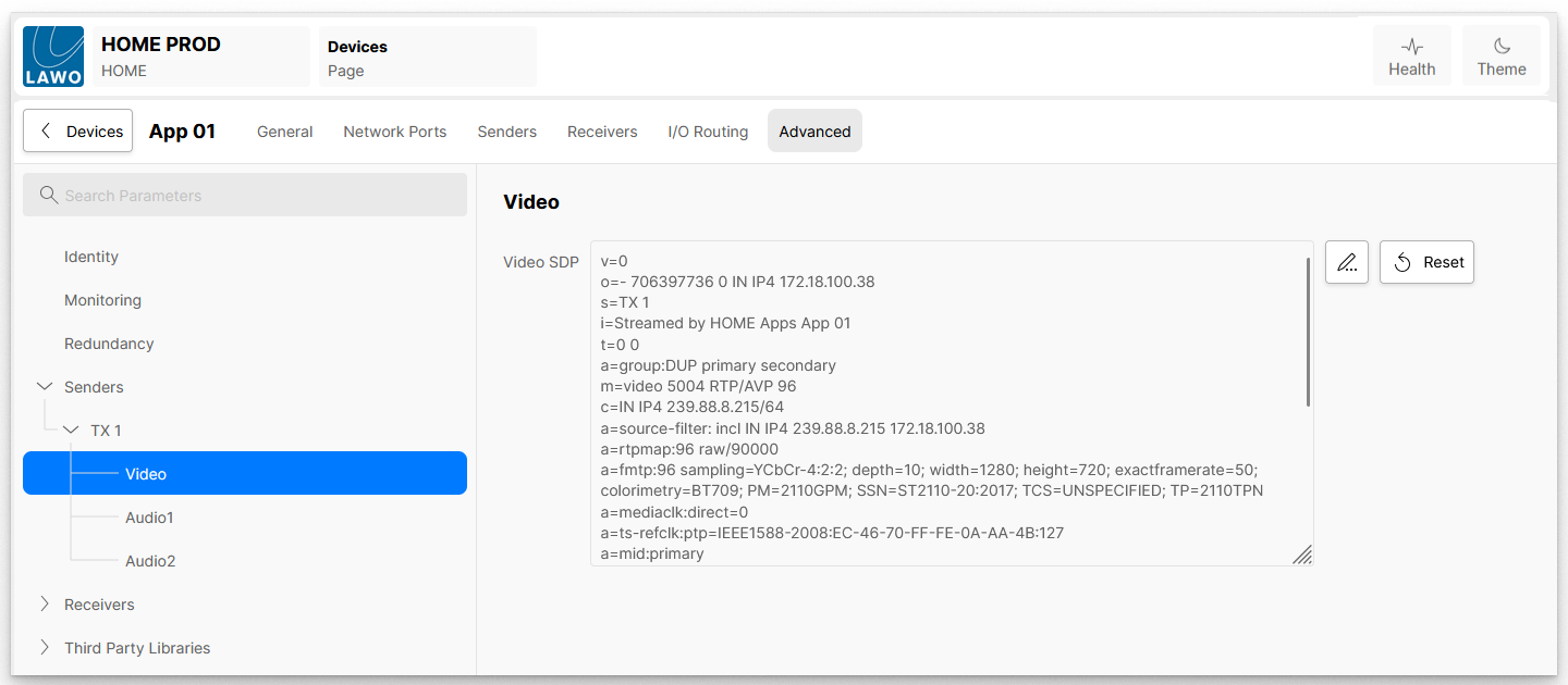
Note that the same SDP data can be accessed from the app's 'Senders' page (as described in HOME Apps - SDP Data).
Video Compression (for JPEG-XS senders)
For SMPTE ST 2110-22 (JPEG-XS) senders, an additional menu item appears: Video Compression.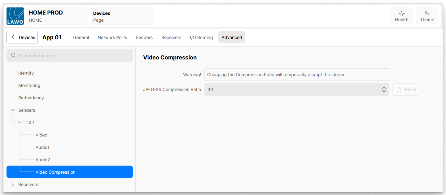
This menu allows the user to specify the JPEG-XS compression level of the video being produced by the app.
The compression level can be changed whilst the app is running. However, doing so will cause a temporary disruption to the video, as the new compression ratio is applied.
The list of compression ratios available is affected by the 'Output Video Compression' control in the app configuration.
For example:
- If the 'Output Video Compression' is set to 'At least 4:1', then compression ratios 4:1 to 20:1 are available.
- If the 'Output Video Compression' is set to 'At least 12:1', then compression ratios 12:1 to 20:1 are available.
SRT Senders
When the app's output video transport is set to SRT, the media stream (SDP) sub-menus are not available and are replaced with SRT and Video Compression.
SRT URLs
The SRT sub-menu provides URLs on which the SRT stream can be requested. A URL is shown for each network interface, in the App Server, which is capable of carrying the SRT stream.
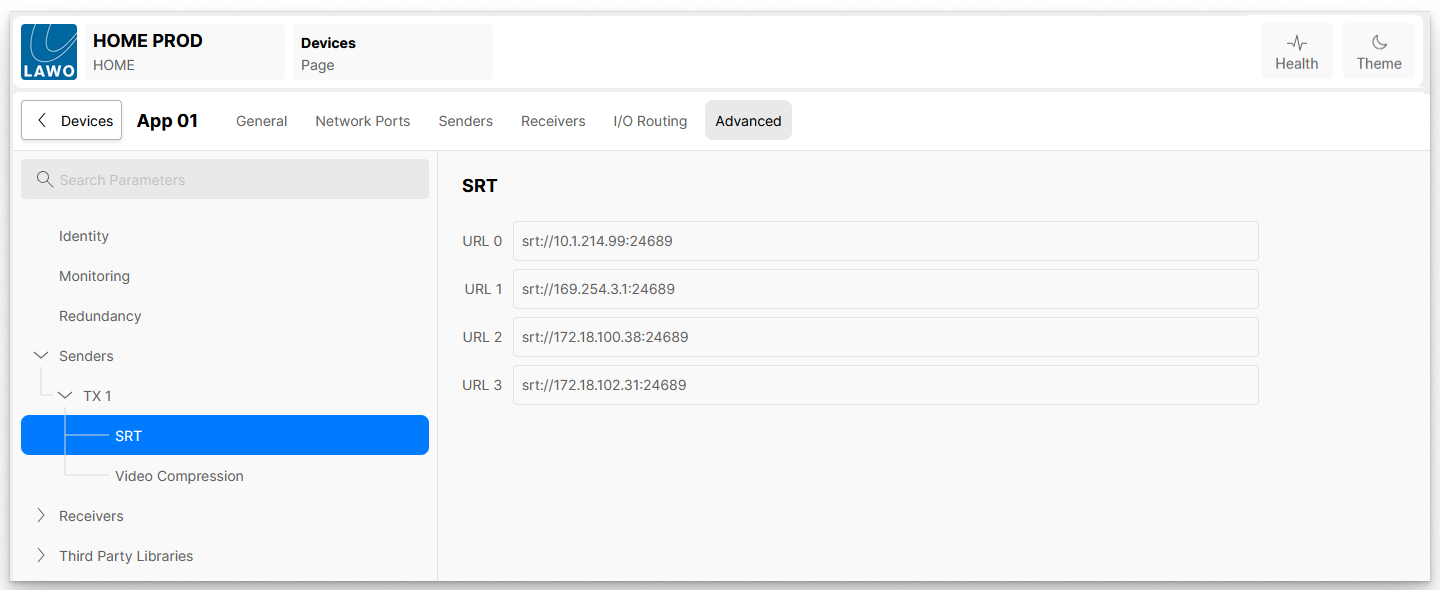
The user is able to connect to the SRT stream using a third-party 'Media Player' application which supports SRT, such as VLC.
To set up the connection, enter one of the URLs provided into the Media Player tool; the tool will then request the stream from the app.
Video Compression
The Video Compression sub-menu allows the user to define the level of compression to be applied to the SRT stream.
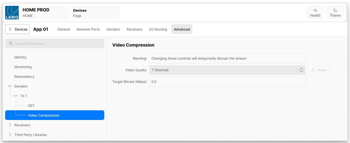
The compression level can be changed whilst the app is running. However, doing so will cause a temporary disruption to the video, as the new compression ratio is applied.
The Video Quality control provides ten predefined target bitrates, plus the option to select 'Use Target Bitrate'.
When the Video Quality is set to Use Target Bitrate, the SRT encoder uses the value entered in the Target Bitrate (Mbps) field to control the level of compression to be applied. It should be noted that this is a target which the encoder will try to achieve; it is not guaranteed that the encoder will be able to achieve the requested bitrate. The table below shows typical bitrates for various frame sizes and quality settings.
| Frame Size | Encoder | Quality 1 "Very Low" | Quality 4 "Low" | Quality 7 "Normal" | Quality 10 "High" |
|---|---|---|---|---|---|
| 1280x720 | CPU/GPU | ~1.6 Mb/s | ~2.3 Mb/s | ~3.0 Mb/s | ~4.8 Mb/s |
| 1920x1080 | CPU/GPU | ~3.3 Mb/s | ~4.5 Mb/s | ~6.5 Mb/s | ~12 Mb/s |
| 3840x2160 | GPU | ~12.5 Mb/s | ~17 Mb/s | ~25 Mb/s | ~42 Mb/s |
Remarks:
- The encoded bitrates are for a frame rate of 50 fps.
- The bitrates are guides only; real values depend on the video contents to a certain degree
- UHD encoding on CPU encoders is done in proxy mode (HD resolution)
WebRTC Senders
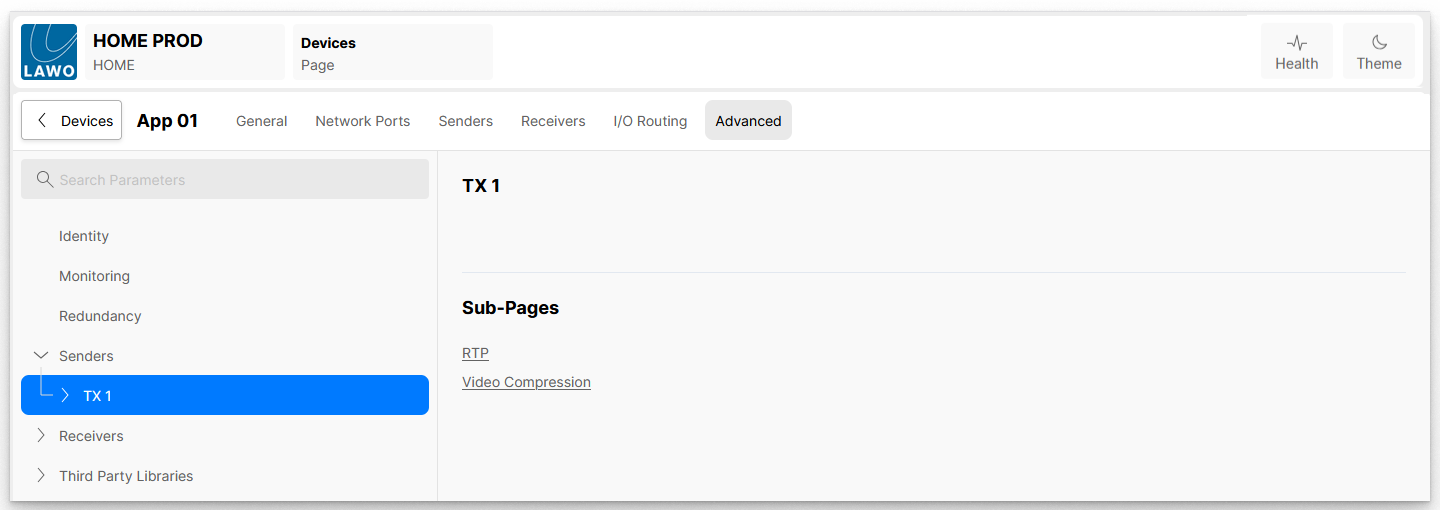
When the app's output video transport is set to WebRTC, the media stream (SDP) sub-menus are not available and are replaced with RTP and Video Compression.
RTP URLs
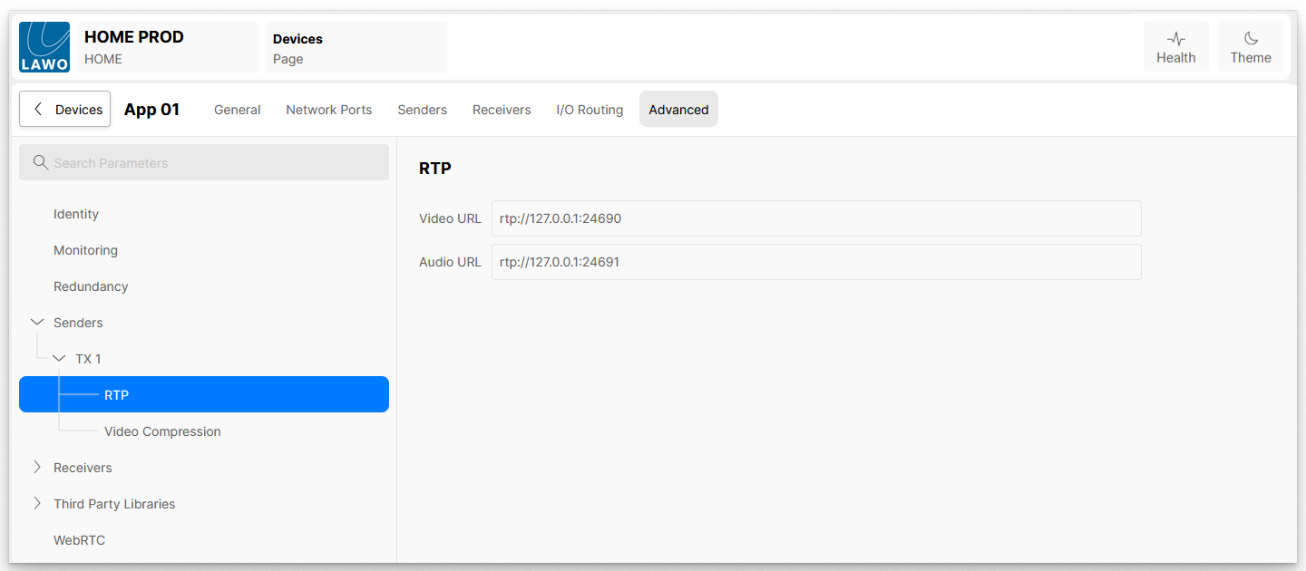
The RTP sub-menu provides URLs on which the media streams can be requested.
Video Compression
The Video Compression sub-menu allows the user to define the level of compression to be applied to the RTP stream.
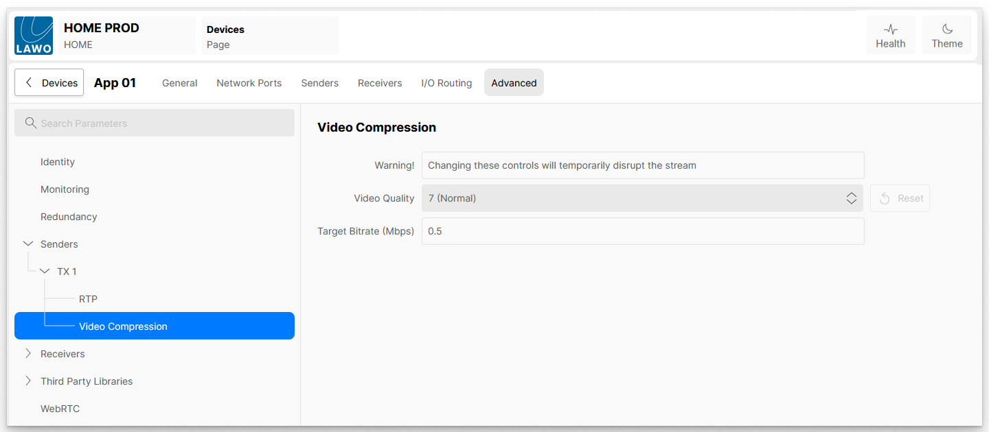
The compression level can be changed whilst the app is running. However, doing so will cause a temporary disruption to the video, as the new compression ratio is applied.
The Video Quality control provides ten predefined target bitrates, plus the option to select 'Use Target Bitrate'.
When the Video Quality is set to Use Target Bitrate, the WebRTC encoder uses the value entered in the Target Bitrate (Mbps) field to control the level of compression to be applied. It should be noted that this is a target which the encoder will try to achieve; it is not guaranteed that the encoder will be able to achieve the requested bitrate. The table below shows typical bitrates for various frame sizes and quality settings.
| Frame Size | Encoder | Quality 1 "Very Low" | Quality 4 "Low" | Quality 7 "Normal" | Quality 10 "High" |
|---|---|---|---|---|---|
| 1280x720 | CPU/GPU | ~1.6 Mb/s | ~2.3 Mb/s | ~3.0 Mb/s | ~4.8 Mb/s |
| 1920x1080 | CPU/GPU | ~3.3 Mb/s | ~4.5 Mb/s | ~6.5 Mb/s | ~12 Mb/s |
| 3840x2160 | GPU | ~12.5 Mb/s | ~17 Mb/s | ~25 Mb/s | ~42 Mb/s |
Remarks:
- The encoded bitrates are for a frame rate of 50 fps.
- The bitrates are guides only; real values depend on the video contents to a certain degree
- UHD encoding on CPU encoders is done in proxy mode (HD resolution)
NDI Senders
When the app's output video transport is set to NDI, there are no sub-pages or controls as the NDI configuration is done at an App Server level.
See HOME Apps - NDI.
Tally
When the Program output is 'On-Air', a control system such as VSM is able to set the User Bits of the Program Out sender. This bit pattern is then automatically applied to the Tally User Bits of the DSK receivers which are currently part of the program output.
For example, if Background A is on the PGM Output, and Keyer 2 is enabled, the Tally bits set on the PGM Out will be mirrored on the tally bits for Background A, Fill 2 and Key 2 inputs.
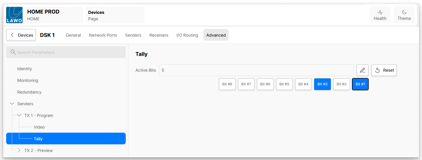
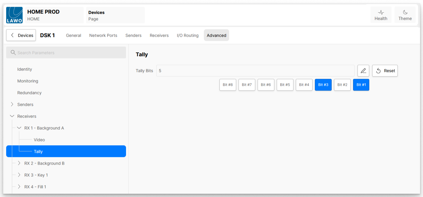
Similarly, any Tally bits set on the Preview output will be mirrored on the receivers which are NOT part of the Program output.
A controller such as VSM is able to then ‘read’ the Tally bits from the receivers and pass this onto another device such as a multiviewer. The Multiviewer would then accurately display tally lamps for the sources which are present in the DSK’s Program out.