.edge - Processing Blades
At the front of the frame are the processing blades (up to 4 per frame). Each blade handles the IP connections plus the SDI conversion and signal processing.
The processing blades are hot-pluggable and so it is possible to add or replace a blade while the frame is powered. See Fitting a Processing Blade for instructions.
Useful to Know
- Each processing blade is an independent entity and can be addressed separately.
- The processing blades are numbered from 1 to 4, starting at the top of the frame.
- Physically, the highest blade is always the master (e.g. slot 1 in a fully-populated frame).
- The master blade determines the fan activity and error reporting.
Internal Components
Internally, each processing blade is based on the latest generation of high-performance FPGAs, featuring high-bandwidth memory (HBM) for high-density, high-performance 100Gbps operation.
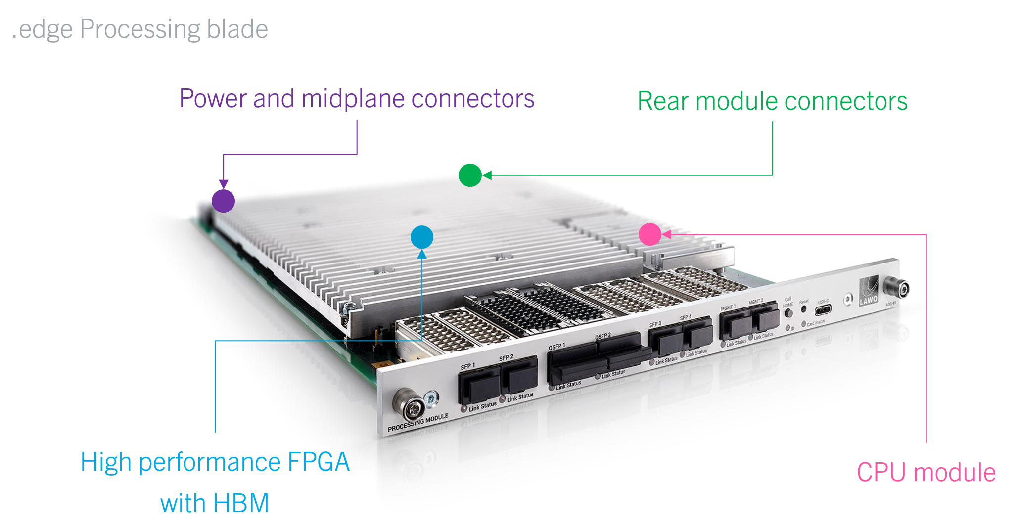
External Connections
Externally, each processing blade is equipped with eight network interfaces: 6 media and 2 management ports.
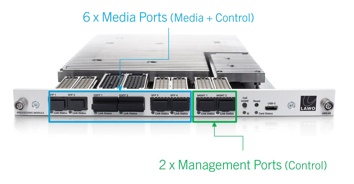
Media Ports
While it is possible to connect all six ports, the active ports are determined by the FPGA mode of the processing blade. Options include 25G (only), 100G (only) or 100G + 25G Proxy (all six ports are active).
Please note:
- 25G comes as standard; 100G requires an optional license.
- 25Gbps is fine for SD and HD; 100Gbps is required for 3G and UHD.
- A 100G license is required to support any of the 100G modes. If a 100G license is not available, then the blade runs in 25G (only) mode and the 100G ports are inactive.
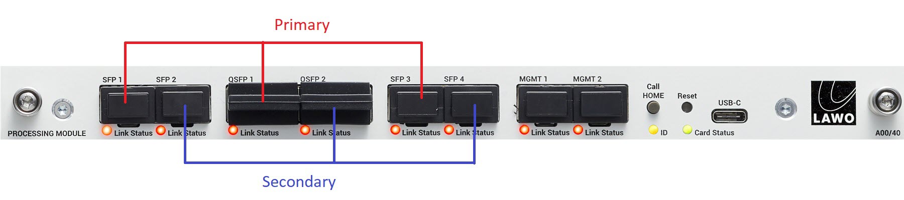
The connections are made as follows:
- SFP 1 to 4 - 4 x 25GbE (via SFP28).
- QSFP 1 & 2 - 2 x 100GbE (via QSFP28).
For each stream, you can decide whether it will be transmitted or received via the primary or secondary port. To achieve redundant streaming, you must use both interfaces.
The image below shows the location of the primary and secondary interfaces.
Management Ports
- Out-of-band - control data arrives via the MGMT ports: 2 x 1GbE (via SFP). This scheme requires a dedicated management network. To achieve redundant control, you must use both interfaces.
- In-band - control data arrives via the media ports. This scheme can be used if there is no separate management network.
Optical Transceivers
To use the network ports, you must fit the correct optical transceivers. These must be Lawo-certified (as described earlier). The optical transceiver determines the cable type, maximum distance and connector.
For more information about how to connect a processing blade, see .edge - Wiring.
Link Status LEDs
| Link Status LED | Meaning | Recommended Actions | |
|---|---|---|---|
Green | Link up (ok). | No action required. | |
Yellow | Link down: optical transceiver detected but no connection. | Check the connection to the network switch. | |
Off | Link down: optical transceiver missing. | Check the fitting of the optical transceiver. | |
Other Controls & Indicators
On the right of each processing blade are the following controls and indicators:
- Call Home (button) and ID (LED) - can be used to identify the hardware in the HOME Web UI.
- Reset (recessed button) - can be used to power cycle the processing blade.
- USB-C (port) - can be connected to perform diagnostics from a service computer.
- Card Status (LED) - shows the health of the processing blade (and chassis on the master blade).
For more information, see .edge - Controls, Connectors and Indicators.
Ordering Information
A processing blade can be ordered using the part numbers .edge_gateway (for a complete SDI I/O package) or A00/40 (for a replacement blade). See .edge - Ordering Information.
Further Information
For information about the supported IP standards, see .edge - Technical Specification.
Additional information such as mechanical drawings and data sheets can be located using the type number: A00/40.