diamond - Metering
diamond supports a number of metering elements that can be used to configure input and output metering. The number of meters, and their design, are determined by the configuration. Options include the meter type, source, scale and color-coding.
Metering Locations
The diamond surface includes a signal present meter on every fader strip. All other meters are optional according to the configuration.
The information below describes the metering defined in the standard configuration. The operation may vary if the configuration is customized.
Metering on the Surface
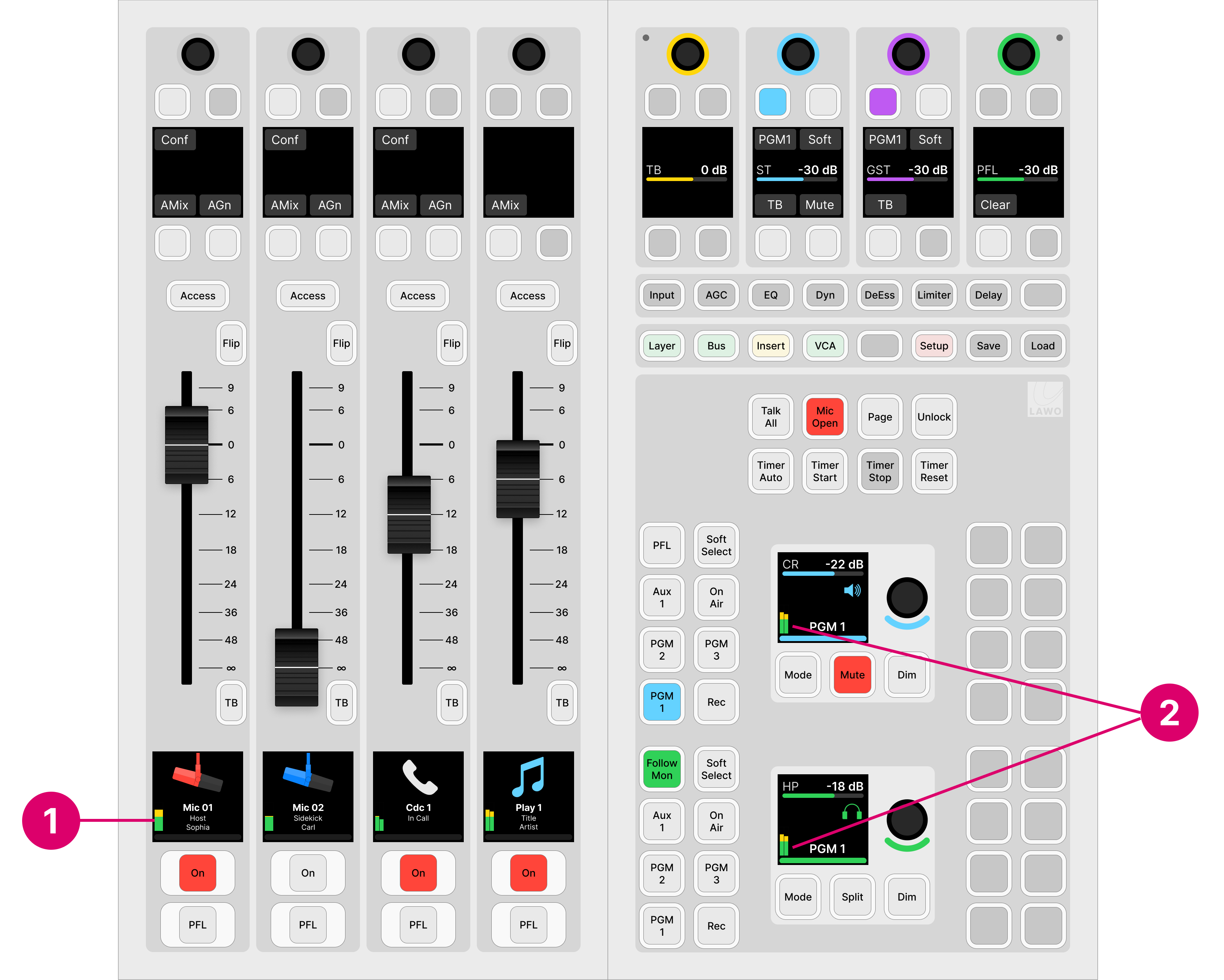
1. Fader Strip Meters
diamond includes a signal present meter in the Source Display on every fader strip.
The metering point is fixed and comes after the source's input section and before all processing.
2. Central/Combo Module Meters
A mono or stereo meter can appear in the two large displays on the Central or Combo module. These meters are defined by the configuration and so their operation can vary.
In the standard configuration, the meters show the level of the CR and HP monitor outputs. The metering point comes after the monitor source selector and before the volume (including mute/dim).
Metering on the GUI
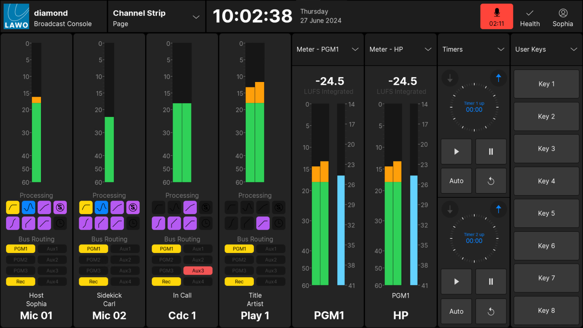
Channel Strip Meters
In the standard configuration, the 'Channel Strip' page provides dedicated metering for every fader strip. The metering point is fixed and comes after the source's input section and before all processing.
The user can decide to show peak metering, momentary loudness or both (using the Channel Strip option in the 'Settings → Meters' dialog box). Note that there is no integrated loudness measurement for a source.
Master Slot Meters
Any of the master slots on the 'Channel Strip' page can be assigned to an output meter. This allows you to meter the main bus outputs and/or a monitoring section. For the bus outputs, the metering point comes after all processing including the fader. For the monitoring outputs, the metering point comes after the monitor source selector and before the volume (including mute/dim).
There are no user options for the output meters, so both peak and momentary loudness bargraphs are always displayed. The numerical readout shows the integrated loudness measurement (in LUFS).
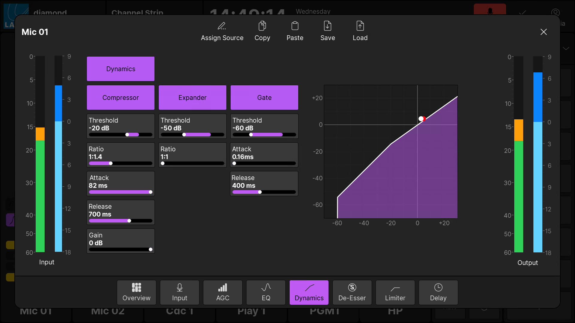
Source Parameter Dialog Box
In the standard configuration, the 'Source Parameter' dialog box includes meters that show the level at the input and output of the processing section. The metering points are shown on the signal flow diagram for a source.
To open the dialog box, press an Access key (on the fader strip) followed by a page option (on the GUI) - e.g. Dynamics.
Peak Metering
In the standard configuration, all of the peak meters are dynamic Peak Program Meters (PPMs). The number of individual bargraphs is defined automatically by the format of the source/bus: 1 for mono; 2 for stereo.
The meters use a digital scale relative to 0dBFS, and provide three color-coded areas: green, orange and red. When signals peak within the orange area, they are at a good operating level. If a meter turns red, then the signal level is overloading.
Loudness Metering
The system provides loudness metering conforming to the ITU-R BS1770. There are two types of measurement: momentary and integrated.
In the standard configuration, both measurements are shown for all outputs, while momentary loudness can be enabled or disabled for all sources.
Momentary Loudness (Bargraphs)
A single blue bargraph represents the average energy of the summed component channels: mono, stereo or surround. The average is measured using either a Momentary (400ms sliding window) or Short term (3s sliding window) integration time.
The color indicates whether loudness is above or below the Target Level:
- Light Blue = equal to, or below, the Target Level.
- Dark Blue = above the Target Level.
The scale markers indicate a tolerance of +/- 1 LU.
Integrated Loudness Measurement (Text Readout)
The integrated loudness measurement is very useful for measuring loudness over a longer period.
The measurement is displayed in LUFS (Loudness Units Full Scale).
The integrated loudness measurement is always on, for all outputs, once the GUI App starts. To comply with the ITU standard, the signal's loudness must be greater than -70 LUFS before an integrated measurement is registered. From hereon, the reading will continue to update over time and represents the average loudness of the output since the start.
The integrated loudness measurement for all outputs can be reset by touching the LUFS value (on any meter) for more than one second.
Compliance with Metering Standards
| Standard Configuration, Version 1.0 | Europe | North America |
|---|---|---|
| Standard | EBU | SMPTE |
| PPM meter scale | dBFS | dBFS |
| PPM mark low | -18 | -20 |
| PPM mark high | -9 | -3 (+17 dBR) |
| Loudness meter (channel, access and slots) | LU EBU +9 (short) | LU EBU +9 (short) |
| Loudness value LUFS (slots) | LUFS -23 (integrated) | LUFS -23 (integrated) |
| Relative System level (OAD) | -36 | -38 |
| Analog Ref Level (OAD) | 18 | 24 |
Operating Level (analog) | 0 dBU | +4 dBU |
Operating Level (digital) | -18 dBFS | -20 dBFS |