diamond VX - Channel Strip Page
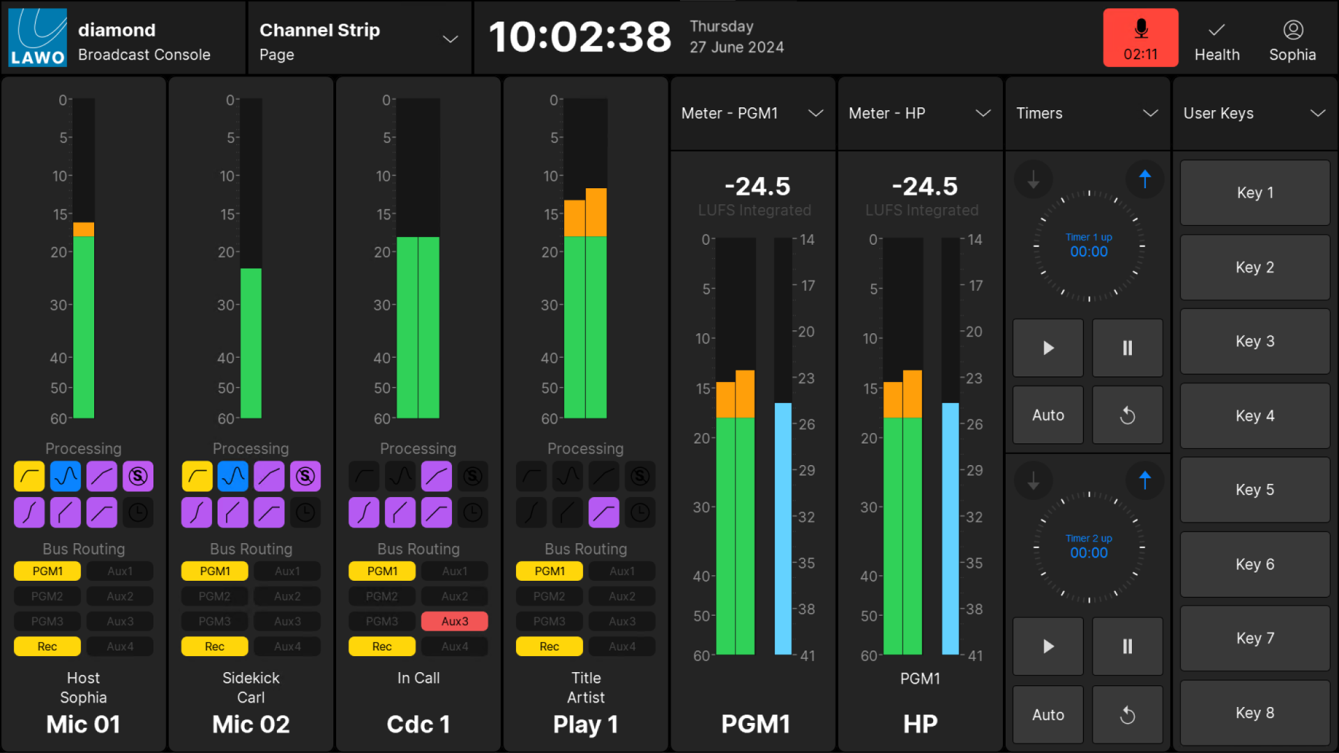
The 'Channel Strip' page is divided into 8 vertical strips that provide an extension of the surface controls.
Two types of strip are supported: channel strips (above the faders) and master slots (above the central controls).
In the example below, there are 4 channel strips (on the left) and 4 master slots (on the right). If your surface is fitted with a Combo module, or the faders are on the right of the central controls, then the layout can be modified using the Combo Module and Swap Slots options (in the 'Settings → Surface' dialog box).
Channel Strip Elements
Each channel strip provides visual feedback for the source assigned to the fader.
Working from top to bottom, there are four areas: input metering, processing, bus routing and the source name / user labels. For security reasons, it is not possible to change settings from these elements. For example, you cannot turn off an EQ by touching its icon.
Input Metering
This area provides dedicated input metering for every fader strip. The user can decide to show peak metering, momentary loudness or both using the Channel Strip option (in the 'Settings → Meters' dialog box).
For more information about the metering scales and characteristics, see diamond - Metering.
Processing
This area shows the on/off status of each DSP module: unlit = off, lit = on. The icons use the Lawo LUX color-coding as follows:
| High Pass Filter | EQ | Compressor | De-Esser |
|
|
|
|
|
|
|
|
| Expander | Gate | Limiter | Delay |
To turn a module on/off, or adjust its settings, press a fader strip Access key to open the Source Parameters and then choose the relevant page.
Bus Routing
This area shows the assignments to the 8 summing buses (defined in the standard configuration). The icons are color-coded to indicate the current status:
- Unlit = source is not assigned (off).
- Yellow = source is assigned (post-fader).
- Red = source is assigned (pre-fader).
To change the bus assignments, press Bus and a page number from the central controls, or press a fader strip Access key to open the Source Parameters.
For more information on editing the bus assignments, see diamond - Bus Assign.
Source Name & User Labels
This area shows the source name (in large text) and user label lines (in small text).
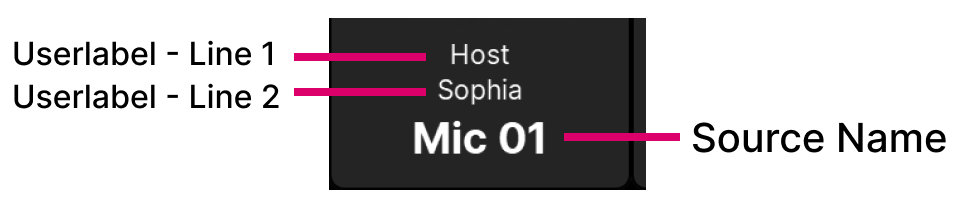
The text can be edited by the user labels editor. In each case, up to 8 characters are supported.
Master Slots
Each master slot is assigned by touching the arrow (at the top right of the slot) and choosing an option.
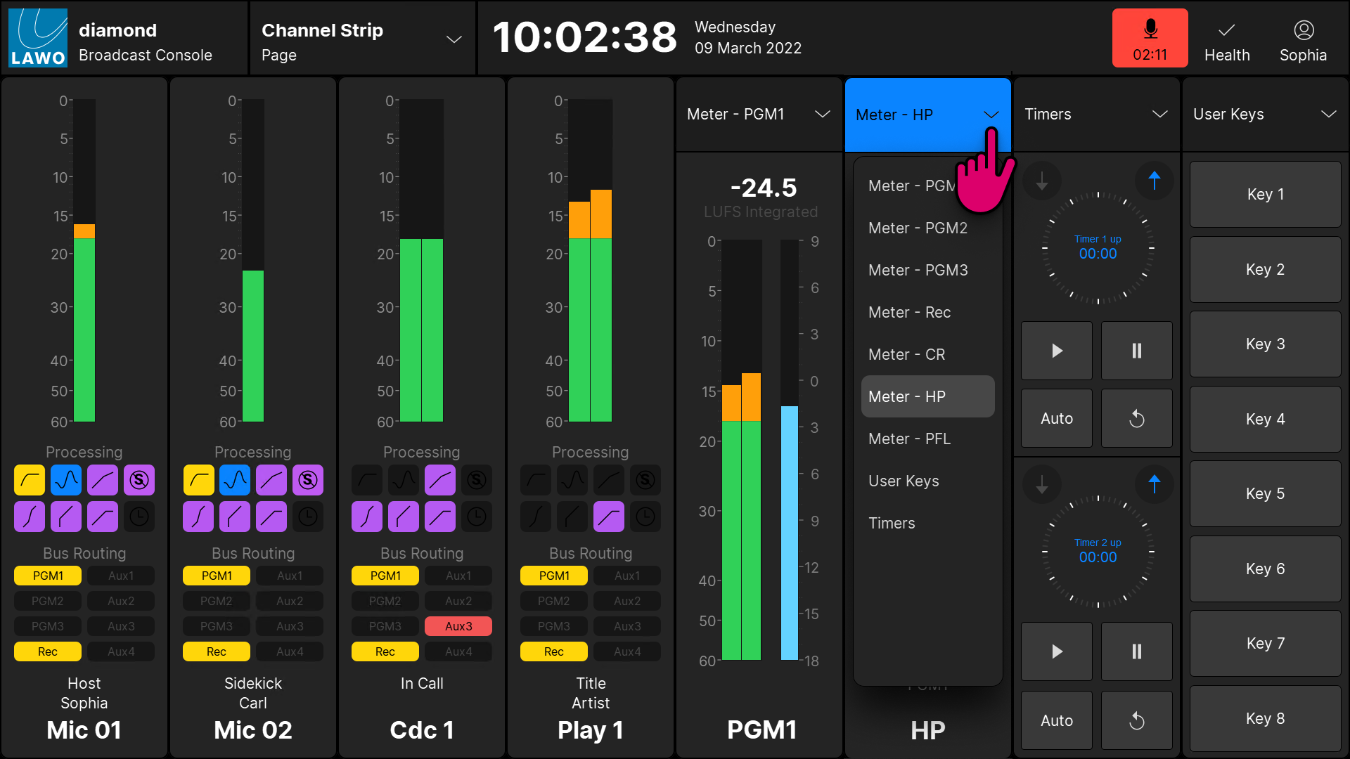
The following functions are supported:
- Meter - PGM x - output metering for a programme bus.
- Meter - Rec - output metering for the record bus.
- Meter - CR - output metering for the control room monitoring.
- Meter - HP - output metering for the headphone monitoring.
- Meter - PFL - output metering for the PFL bus.
- User Keys - 8 programmable user keys (requires configuration).
- Timers - two count-up/count-down timers.
Output Metering
There are no user options for the output meters and so both peak and momentary loudness bargraphs are always displayed. The numerical readout shows the integrated loudness measurement (in LUFS).
For each of the main bus outputs, the metering point comes after all processing including the fader. For the monitoring outputs, the metering point comes after the monitor source selector and before the volume (including mute/dim).
For more information about the metering scales and characteristics, see diamond - Metering.
User Keys
The 8 user keys are defined by the configuration. In the standard configuration, nothing is programmed and so the functions must be configured using VisTool Editor and the ON-AIR Designer.
Timers
Each timer has two modes of operation: count-up or count-down, and can be triggered either automatically or manually. The full operation is described later in Timer Operation.