Power Core RP v2 - Wiring
Once the frame is populated and mounted, you are ready to cable the device.
This topic covers both of the current hardware revisions. Note that the front panel connectors differ slightly, while the rear panel is the same for both revisions.
To configure the system, only power (10) and control (1) are required.
To get the system operational, the following connections are required: control (1), streaming (2), expansion I/O (8), grounding (9) and power (10).
In an mc2 installation, the following connections are unused: CAN (4) and RS-422 (5).
Connector Summary
Revision 3


1. CONTROL : 2 x 1GbE control ports (via SFP) - used to connect Power Core to the control network/surface via IP. One connection is essential to configure the device.
2. RAVENNA/AES67: 4 x 1GbE streaming ports (via SFP) - used to stream audio signals to and from the media network.
3. MADI/AIOX: 4 x MADI or AIOX ports (via SFP) - can be used to connect local MADI or Audio I/O Extenders.
4. CAN : 1 x 500Kb/s CAN port (CAT5e, RJ45) - unused.
5. RS-422 : 1 x serial port (RJ45) - unused.
6. USB (revision 3 only): 1 x USB port - can be used for debugging. On a revision 2 frame, the RS-422 serial port may be used for debugging.
7. WCLK : IN & OUT (BNC) - can be used to connect the system's sync reference to other devices.
8. Expansion I/O (various) - used to connect local audio and GPIO signals.
9. Functional Earth (M4x8 screw) - must be used to ground the frame.
10. Power Inputs: AC & DC (IEC & Kycon) - used to connect power to the frame. One connection is essential; the other provides redundancy.
Revision 2
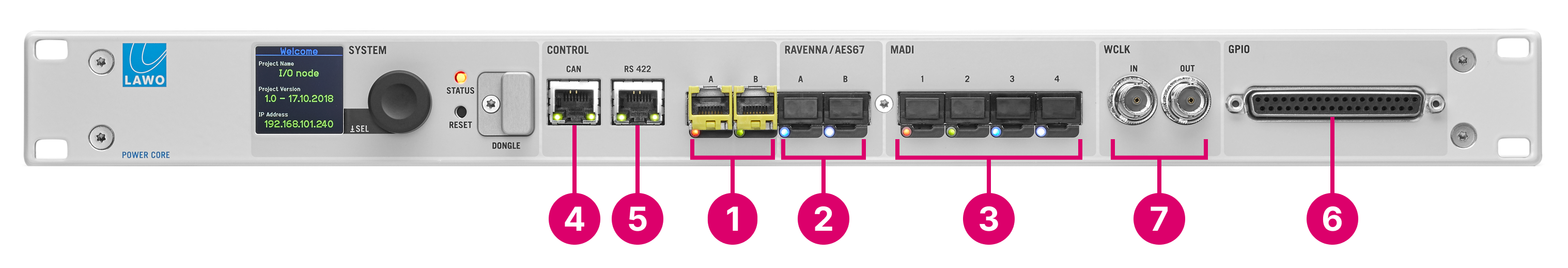
As above, except for:
2. RAVENNA/AES67 - on a revision 2 frame, there are two RAVENNA/AES67 ports: 2 x 1GbE streaming ports (via SFP).
6. GPIO - on a revision 2 frame, GPIOs are always included: 8 x GPI and 8 x GPO (DB-37).
On a revision 2 frame, there is no USB connector for debugging. Instead, the RS-422 serial port (5) can be used for this purpose.
The rest of this topic describes the connections. For pinning information, see Connector Pin-Outs.
- CONTROL Ports
- USB Service Port (revision 3 only)
- Wordclock IN & OUT
- GPIO
- Expansion I/O
- Functional Earth
- Power Inputs: AC & DC
CONTROL Ports
The two network CONTROL ports (dwc0 & dwc1) are used for administration and control. They can be used to remotely control Power Core via TCP/IP; to network Power Core to other devices; and to update the system firmware and configuration.
In an mc2 installation, the control ports are initially used to set up the device and then connect it to the same management network as the mc2 control system.
On a Power Core revision 2 frame, the ports provide the same functionality but are labelled differently: CONTROL A = dwc0 and CONTROL B = dwc1.
At least one port must be connected initially to configure the device's network settings. The port(s) can then be used to connect Power Core to a dedicated control network (for out-of-band control). Usually, only the first port (dwc0) is connected. If both ports are used, then redundancy can be implemented via LACP or a generic link failover mode. dwc0 & dwc1 – always active: 2 x 1GbE* (via SFP).
The connection(s) can be made either directly or via a network switch.
When connecting via a network, then this can be shared with other devices, such as in the regular "house network" of a typical broadcast facility. Routers are permitted as long as the minimum requirements of the network interfaces are met. By using routers, or similar devices, the latency of the communication will increase.
*
- Speed = 1Gb/s, 100Mb/s or 10Mb/s; 1Gb/s is recommended
- Duplex mode = Full Duplex
It is important to keep the control network separate from the streaming network connected to the RAVENNA/AES67 ports (2).
To use the control network ports, you must fit the correct SFP modules. These must be Lawo-certified (as described earlier). The SFP determines the cable type, maximum distance and connector.
Each port has an LED which indicates the following information.
| CONTROL Port LED | Meaning |
|---|---|
| Off | link down |
| Green | link up, speed = 100 Mb/s |
| Blue | link up, speed = 1000 Mb/s |
RAVENNA/AES67 Ports
The four RAVENNA/AES67 ports stream audio to and from an IP network. In an mc2 installation, they are used to stream audio signals to and from the mc2 system via the media network.
- ra0 & ra1 – always active: 2 x 1GbE (via SFP).
- ra2 & ra3 (revision 3 only) – requires the AddOnRAV+ license: 2 x 1GbE (via SFP).
The first pair of interfaces are enabled as standard: ra0 & ra1. The second pair of interfaces can be enabled by purchasing the optional AddOnRAV+ license: ra2 & ra3.
On a Power Core revision 2 frame, there are two streaming interfaces: ra0 & ra1. They provide the same functionality but are labelled differently: RAVENNA A = ra0 and RAVENNA B = ra1.
The streams are fully compatible with SMPTE ST2110-30/31, AES67 and RAVENNA. To achieve redundant streaming, compatible with SMPTE ST2022-7, you must use both interfaces: ra0/ra1 (or ra2/ra3 on revision 3).
Using the first pair of interfaces only, the total Audio over IP capacity is up to 256 I/O channels. The Power Core RP v2 can be configured with 32x8 channel streams, 16x16 channel streams, or 4x64 channel streams. Using the VisTool RP application it is possible to enable or disable individual stream transmitters. By default, all streams are configured to use both interfaces.
If the second pair of interfaces is enabled (on revision 3), then the total Audio over IP capacity doubles: up to 512 I/O channels, with either 64x8 channels streams, 32x16 channel streams, or 8x64 channel streams.
The senders and receivers are pre-defined in the configuration file. The configuration of the senders and receivers can be modified using ON-AIR Designer.
The connection(s) must be made via a network switch and not directly to another streaming port. You can find more details about the data network requirements and suitable components in the Lawo IP Networking Guide.
Important: The media network must be properly managed and configured. i.e. it must use a suitable network architecture; all components must support multicast (as opposed to unicast); a proper Quality of Service (QoS) must be configured; and so on. Please DO NOT attempt to connect the streaming interfaces using an unqualifying IP network, as correct operation cannot be guaranteed.
To use the streaming network ports, you must fit the correct SFP modules. These must be Lawo-certified (as described earlier). The SFP determines the cable type, maximum distance and connector.
Each port has an LED which indicates the following information.
| RAVENNA/AES67 Port LED | Meaning |
|---|---|
| Off | link down |
| Green | link up, speed = 100 Mb/s |
| Blue | link up, speed = 1000 Mb/s |
MADI/AIOX Ports
Each of the four MADI/AIOX ports has two possible modes of operation: either MADI (conforming to AES10) or AIOX (a proprietary protocol).
In MADI mode, the ports can be used to connect multi-channel digital audio to Power Core.
- Each port conforms to AES10 and carries up to 64 bi-directional channels (at 48kHz).
- Ports 1&2 and 3&4 can be dual-redundant.
- Dual-redundancy is defined in the ON-AIR Designer.
In AIOX mode, the ports can be used to connect a Power Core Audio I/O Extender (described earlier).
- The AIOX protocol carries both audio and control to the external device.
- Ports 1&2 and 3&4 can be dual-redundant.
- Dual-redundancy is defined in ON-AIR Designer.
It is possible to mix and match the two modes. For example, to use ports 1 & 2 for a dual-redundant MADI connection and ports 3 & 4 for two non-redundant connections to two audio I/O extenders. The mode of operation is defined by the ON-AIR Designer (via the "Frame → System Core" configuration).
- 1, 2, 3, 4 – always active: 4 x MADI or AIOX (via SFP).
All MADI and AIOX connections must be point-to-point.
To use a MADI or AIOX port, you must fit the correct SFP module. These must be Lawo-certified (as described earlier). The SFP determines the cable type, maximum distance and connector.
Each port has an LED which indicates the following information.
| MADI/AIOX Port LED | Meaning |
|---|---|
| Off | not configured |
| Red | signal not present |
| Green | signal present |
| Blue | signal present & active |
| Light Blue | signal present & not active |
CAN Bus Port
In an mc2 installation, the CAN port is not used. It should be left unconnected.
RS-422 Serial Port
In an mc2 installation, the RS-422 serial port on revision 2 frames can be used for debugging. On revision 3 frames, it is not used and should be left unconnected.
USB Service Port
The USB (type B) port is included on revision 3 frames only. It can be used to connect a service computer for debugging.
The port supports plug and play operation so, after connecting your computer, the device should be assigned a Com port number automatically. Enter this into your terminal emulation software tool to establish a connection. For step-by-step instructions, please see Power Core RP v2 - USB Service Port.
Wordclock IN & OUT
The two WCLK connectors can be used for external synchronization. If Ravenna streams are being used, the Power Core RP v2 must be synchronized to PTP arriving from the streaming network OR must be configured as a PTP Master. If the Power Core RP v2 is a PTP Slave:
WCLK IN will not be used.
WCLK OUT provides an output of the current system reference. It can be used to distribute a wordclock signal to non-PTP devices.
If the Power Core RP v2 is a PTP master
WCLK IN can be connected to provide an external sync reference
WCLK OUT provides an output of the current system reference. It can be used to distribute a wordclock signal to non-PTP devices.
The connections are made using standard 75 ohm BNC connectors. The maximum cable length depends on the equipment you are connecting to.
See Power Core RP v2 - Synchronization for more information.
GPIO
The front panel GPIO connector is included on revision 2 frames only. It provides 8 x GPI (optocouplers) and 8 x GPO (silent and self-healing relays).
On a Revision 3 frame, GPIOs can be added by fitting up to two rear expansion GPIO cards (described below). Note that rear expansion GPIO cards can also be added to revision 2 frames (to expand the number of GPIOs).
Expansion I/O Cards
Power Core RP v2 supports up to 8 expansion I/O cards (as described earlier).
All rear panel I/O cards, except the Dante, GPIO, MADI, and MADI SRC cards break out on DB-25 connectors that are wired according to the AES59 (TASCAM) standard.
MIC/LINE IN
All MIC/LINE IN connections are electronically balanced and floating (suitable for balanced or unbalanced use). They feature a discrete class-A preamplifier with superb performance at both low (mic) and high (line) levels. In addition to variable microphone pre-amp gain, each input comes with switchable 48V phantom power, a high-pass filter and 20dB PAD. The pre-amp gain can be automatically adjusted using the AutoGain feature. The maximum analog input level (with the PAD enabled) is +24dBu.
LINE IN & LINE OUT
All LINE IN and LINE OUT connections are electronically balanced and floating (suitable for balanced or unbalanced use). For LINE OUTs, the maximum analog level can be adjusted to +12, +15, +18, +21 or +24 dBu relative to digital full scale (dBFS). This is a factory-configured setting; +24dBu is recommended.
AES3
All AES3 connections conform to the stereo AES3 standard. The inputs have sample rate conversion (SRC).
MADI
The two ports on a MADI I/O card (710/50) meet the same specification as the front panel MADI/AIOX ports. This allows them to use for either MADI or an Audio I/O Extender. See MADI/AIOX.
The single port on a MADI SRC I/O card (710/60) provides 64 bi-directional channels with SRC on the inputs. Note that this card does not support AIOX and so it cannot be used for an Audio I/O Extender.
DANTE
The DANTE card provides 1 x DANTE Brooklyn III module with 1 main + 1 redundant port.
Each port supports up to 64 bi-directional channels (at 48kHz).
The connector and cable type is RJ45, CAT 5 or better (CAT 5e/6/7); straight or crossed Ethernet cable. The supported standard is Gigabit Ethernet (1000 Base-Tx). The maximum cable length is up to 80m.
The configuration of the DANTE Brooklyn modules depends on their firmware version. Please refer to your Lawo software release notes for the latest information.
For more information about DANTE networking, please refer to the manufacturer's website at: https://www.audinate.com/
GPIO
The GPIO card provides 8 x GPI (optocouplers) and 8 x GPO (silent and self-healing relays) for local signaling and switched functions, plus two VCA inputs to remotely control variable parameters.
- GPI = 8 x optocouplers (3-36V DC / 8mA @ 36V)
- GPO = 8 x Opto-MOS relays (50V AC / 120mA @ 50V)
- 2 x voltage-controlled inputs.
The connector is a 37-pin D-type (DB-37), female.
Functional Earth
The M4x8 grounding screw must be used to ground the frame for EMC reasons.
See Power Core RP v2 - Grounding.
Power Inputs: AC & DC
Power Core comes with dual power feeds: AC and DC. To use the DC input, you will need the external DC power supply which must be ordered separately. If both inputs are connected, then the two feeds provide main and redundant power.
- 12V In (Kycon) – DC input
- 100-240V In (IEC) - AC input
Before connecting power to the device, please read and observe all of the important safety information in the Power Core RP v2 - Power Supplies topic.