mc²96 - Channel Signal Flow and Options
On the mc2 consoles, every DSP channel includes a full set of signal processing modules: EQ, Dynamics, Delay, etc. This allows you to apply processing to both input channels and audio masters.
The Channel Config display can be used to change the order of the processing modules for any DSP channel: Input, Group, Aux or Sum, including the pickup points for the insert send and direct out. You can use this to customize the signal flow on a channel-by-channel basis. All changes are saved and loaded with both snapshots and productions.

Editing the Channel Signal Flow
- Press the CHAN button on the SCREEN CONTROL panel.
- Select Channel → Channel Config from the GUI page menu.
- Press CTRL + 3 on the console keyboard.
2. Select a channel to edit - either by pressing its fader SEL button or using the Access/Assign panel.
You can use the Couple group to adjust parameters across multiple channels.
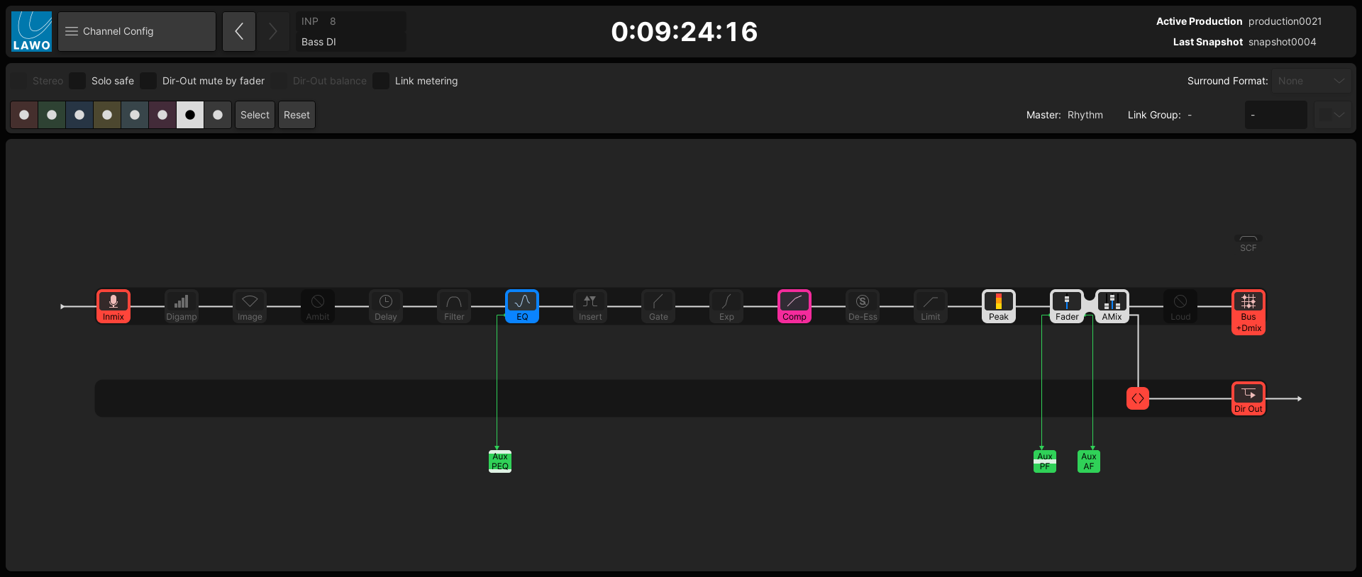
The main part of the display shows the signal flow for the channel in access – in our example, INP 8.
The DSP modules are lit (if the module is turned on), and unlit (if the module is off). The colors used follow the Lawo Lux color-coding scheme: red for gain; yellow for balance/pan; magenta for dynamics; blue for EQ; cyan for delay; green for aux sends; white for level/metering.
Apart from InMix and Bus, the modules can be positioned in any order. The Image module is available for stereo channels only. The Ambit (upmix) module is available for 5.1 surround channels only (via the surround VCA).
Note that the Aux send pick-up points are shown for information purposes only (as each individual send can be switched to a different pick-up point). See mc²96 - Aux Sends.
3. Using the touch-screen or trackball, select the processing module you wish to move.
The module is highlighted with an outline.
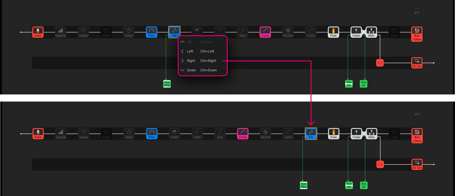
4. Right-click and choose an option from the context menu, or press a soft key (on the SCREEN CONTROL panel).
- Left or Right – moves the module left or right within the main channel signal path.
- Up or Down – moves the module up or down into the direct output path.
You can also press CTRL + Left/Right/Up/Down on the console keyboard to move the selected module.
The screenshots below shows how to move the EQ module.

5. For the Peak and Loudness modules, the options change the metering point.
In this instance, the available options are pre-defined; you cannot freely position the meters. See mc²96 - Meter Pickup Points.
6. For the Loudness module, there is an additional option to turn the loudness metering ON.
This can be used to enable loudness metering on a channel-by-channel basis.
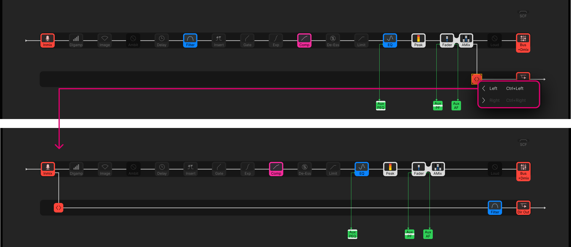
7. For the channel's direct out, you can change the pickup point and apply processing:
- Use the <> icon to move the pickup point.
- Select a module (e.g. Filters) and right-click to move it Down into the direct output path.
In the example below, it is possible to apply equalization to the main channel and direct out independently (via the EQ in the main path and Filters in the direct out).

Other Channel Options
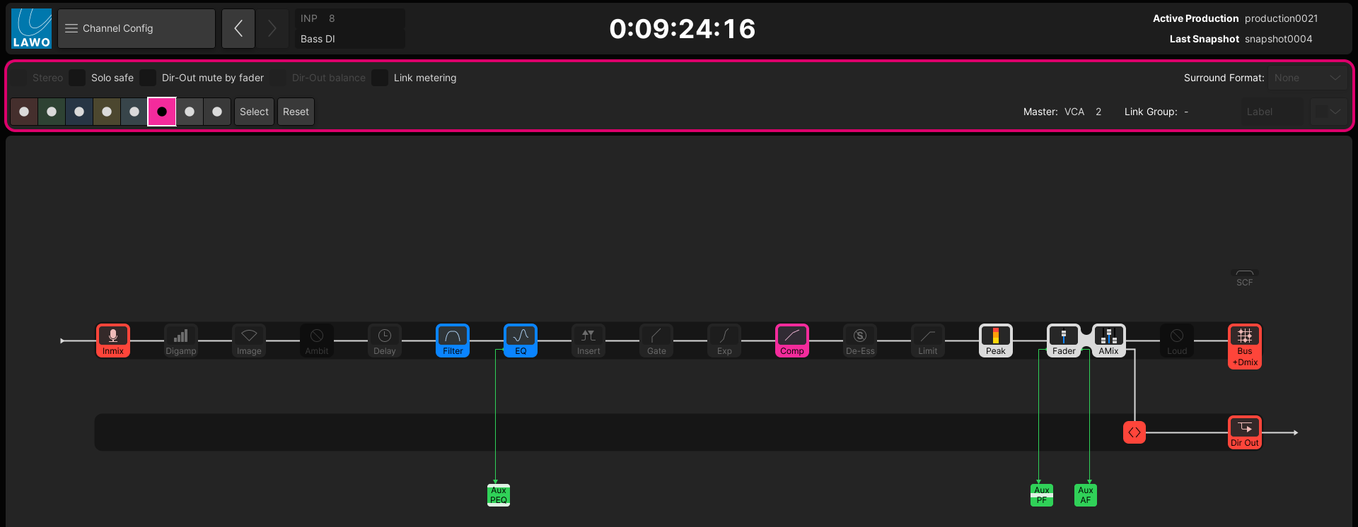
At the top of the Channel Config display are a number of other channel options.

If an option is unavailable, then it is "greyed out" - for example, you cannot select the Stereo option on an even-numbered DSP channel.
In each case, touch or click to enable (or disable) the option.
- Stereo - enables stereo channel linking (if there is a valid channel in access).
- Solo Safe - enables solo safe to prevent the channel being muted when a Solo-in-place is active.
- Dir-Out mute by fader - sets the channel's direct output to mute automatically when the channel fader opens.
- Dir-Out Balance - determines whether the channel pan position affects the direct output. Available for stereo channels only.
- Link metering - enables link group metering on the channel meter. Available if the channel is part of a link group.
- Downmix - enables the downmix matrix for a surround channel. Available for Surround VCA masters only.
- Color (boxes), Select and Reset - assigns a channel color.
- Master - shows the name of any VCA or Surround VCA masters (if applicable).
- Link Group - shows the name of any Link groups (if applicable). The Label field can be used to edit the link group label.
- Surround Format - enables surround channel linking (if there is a valid channel in access).