mc²96 - Input Control
This topic describes all possible input parameters and the methods of control. For a quick guide to adjusting source gain, see mc²96 - Input Gain and Metering.
Input Parameters
- For a mic/line input, there are two sets of parameters: source parameters (in the remote preamp) and InMix parameters (in the channel DSP).
- For other types of input, there are no separate source parameters and so input gain is always adjusted in the channel's InMix DSP.
- If an input channel is stereo, then a number of additional parameters become available: Balance, Mono, Left/Right reverse, etc.
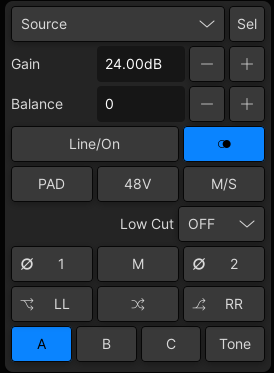
- GAIN - source gain.
- For mic/line inputs, the source gain range depends on the I/O device.
- The InMix gain can be adjusted from -128dB to +80dB.
- BAL - left/right balance (for stereo channels only).
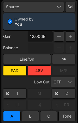
- PAD, 48V, Low Cut - analog source settings for a mic/line input: -20dB PAD, 48V phantom power, low cut filter.
- Keep pressing the Low Cut button to cycle through the cut-off frequency options: Off, 40Hz, 80Hz and 140Hz.
- The LINE button can be used to switch to line level (for a different gain range and no PAD or 48V).
- Ø1 phase reverse (left) and Ø2 phase reverse (right).
- M/S - Middle and Side decoding (for stereo channels only).
- M, L→B, R→B, L/R - mono, left to both, right to both, left/right reverse (for stereo channels only).
- A, B, C - alternate input switching (if alternate sources are configured).
- TONE - tone to channel.
Operation
The parameters can be controlled (for the selected channel) from the INPUT panel (on the Central Control Section) or Main Display.
 |
|
Alternatively, you can use the upper rotary control on the fader strip (to adjust source gain) and the Channel Display touch-screen to adjust 48V, PAD, etc.
Input parameters can also be assigned to the Free Controls and user buttons on a channel fader strip. e.g. for fast access to L→B and R→B.
If a parameter is not supported, then it cannot be controlled from the front panel and is greyed out on the touch-screen displays.
Mic/Line Inputs
For a mic level signal:
- Deselect the Line/On button (unlit).
- Use the GAIN control (in Source mode) to remotely set the mic preamp gain.
- Press the 48V button to select 48V phantom power.
- Press PAD to insert the PAD.
- Press the high pass filter button to insert an analog subsonic filter.
- Keep pressing to cycle through the roll-off frequency options: Off, 40Hz, 80Hz and 140Hz.
For a line level signal:
- Select the Line/On button (lit).
- Use the GAIN control (in Source mode) to remotely set the line-level input gain.
- Insert a high pass filter as described above.
InMix Gain
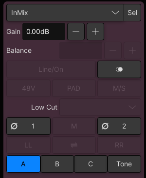
The input GAIN control can be switched to InMix mode to adjust input gain in the channel DSP, after the A-D conversion.
1. Select InMix from the drop-down menu in the Main Display.
Whenever InMix mode is selected, the input controls on the Main Display change color to purple.

2. Use the GAIN control (in InMix mode) to adjust the InMix gain.
3. The Source/InMix mode also affects the Sel button: select Source + Sel to select source gain, or InMix + Sel to select InMix gain.
Other Source Types
For other types of input there are no separate source parameters and so input gain is always adjusted in the channel's InMix DSP. This applies to fixed-level analog inputs, digital inputs (AES3 or MADI) and internal signals.
The system takes care of this automatically, so there is no need to switch the mode on the Main Display.
Other I/O parameters such as SRC on/off, etc. must be adjusted from the Signal Parameters pop-up in the Signal List display.
Phase Reverse
The Ø1 and Ø2 buttons reverse the phase of the channel input. In the case of a mono channel, you can select either button. If the channel is stereo, then use Ø1 to reverse the left leg and Ø2 to reverse the right leg.
Phase reverse is handled by the InMix module (in the channel DSP).
Stereo Input Control
 |  |
- BAL - left/right balance.
- Ø1 - phase reverse (left) and Ø2 phase reverse (right).
- M/S - Middle and Side decoding (described below).
- MONO (M) - sums the left and right inputs.
- L→B (LL) - assigns the left source to both inputs.
- R→B (RR) - assigns the right source to both inputs.
- L/R - reverses the left and right inputs.
M/S (Middle & Side) Decoding

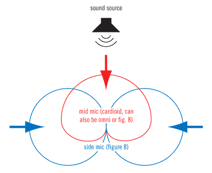
M/S is a stereo recording technique which uses two coincident microphones, one pointing to the front (Middle) and the other (bi-directional) at right angles to provide the stereo ambience (Side). The mc2 consoles provide M-S to X-Y decoding to turn the Middle and Side signal into normal Left and Right stereo.
First create a stereo channel and assign its inputs as follows:
- Left Input - from the Middle (M) signal, usually a cardioid or omni-directional mic.
- Right Input - from the Side (S) signal, always a figure-of-eight.
When the M/S button is active, the following matrix calculations are applied:
- Left channel = L+R (M+S)
- Right channel = L-R (M-S)
By adjusting the BALANCE control, you can vary the ratio of Middle to Side, and thereby adjust the width of the stereo field.
A/B/C Input Switching
For each input channel, you can assign up to three sources (A, B and C) that can be switched individually (per channel) or globally (for a range of channels). They can be used to provide fast access to a backup source if the main source fails. Or, to switch a range of channels to playback.
The A and B sources can be switched from the fader strip or Central Control Section, while all three sources (A, B and C) can be switched from the Central GUI (via the Main Display).
To use this feature, the sources must be assigned from the Signal List display (as described earlier). The A and B buttons on the surface, and A, B and C buttons on the GUI, can then be used as follows:
- Press A, B or C to switch the channel between its main source (A) and backup source (B or C). If there is no source assigned, then the corresponding button cannot be selected.
- Use the GAIN control (in Source mode) to set an independent gain value for each source.
- Use the GAIN control (in InMix mode) to adjust the channel input gain after the A/B/C input switch.|
TONE to Channel
The TONE button switches test tone to the channel.
Note that this function can only be selected on input channels, and temporarily replaces the channel's source.
By default, the first sine wave from the internal signal generator is used as the test tone source.
- Press TONE to switch the test tone signal to the channel. The channel's source is replaced and all other INPUT controls are disabled.
- To adjust the level or frequency, open the Signal Parameters pop-up for the Sine 1 source.
- Switch off TONE to return the channel to its assigned source.
Advanced Tone to Channel Options
The following options can be programmed from the Custom Functions display using the Test Tone Button function.
- Specify a different test tone source for mono, stereo and surround channels.
- Program a fader user button to emulate the TONE button. This provides fast, direct access to tone switching across the console.
- Program a central user button to turn off all TONE to channel selections. This allows you to switch off tone to all channels, globally, from a single button push.
