mc²96 - Channel Display
The Channel Display is a high resolution touch-screen display that provides visual feedback and metering for the channels assigned to the fader strips.

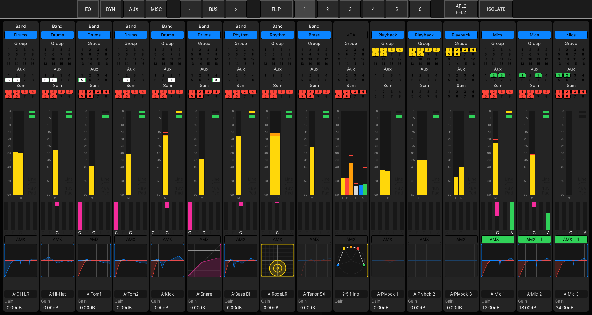
Channel Display (with single metering row)
The display can include up to three "metering" rows.
- The first (lower) row is always present and shows information about the channels assigned to the current bank and layer.
- The second and third (upper) rows are optional, and show either the flip layer of the current bank OR a specific bank and layer.
Above the first metering row is a horizontal strip of buttons that provide isolated bay controls and local bank/layer switching.
First Metering Row
The first metering row is always present and shows information about the channels assigned to the current bank and layer.
Strip Layout
Each of the informational elements can be hidden from view by turning off the corresponding "Channel Display → Strip Layout" option in the System Settings display. This can be used to simplify the display or make space for the additional metering row(s). Note that the channel meter and source gain indicator are always present and cannot be hidden.
Channel Display Elements
From top to bottom, the elements are:
- AFV – the Audio Follow Video event number plus a camera icon if the event is active.
- VCA – the name and color coding of the VCA or Surround VCA master(s).
- You can choose how many nested VCA masters are shown using the "Channel Display → Bay/Main VCA Count" options in the System Settings display.
- Link – the name and color coding of link groups.
- N-1 – the name and color coding of the mix minus bus.
- Group, Aux, Sum – the assignments from the channel onto the Group, Aux and Sum buses.
- Each indicator represents a mono destination. So, for a 5.1 Sum, you will see all six individual assignments: e.g. Sum 1 = L; Sum 2 = R; Sum 3 = C; Sum 4 = LFE; Sum 5 = Ls; Sum 6 = Rs.
- The bus types are color-coded for easy identification: Groups (yellow), Auxes (green) and Sums (red).
- The Aux colors vary slightly depending on the pickup point of the aux send: full green = post-fader; white/green = pre-fader; green/white = pre-EQ.
- You can choose how many buses of each type are shown using the "Channel Display → Bay/Main Bus Count" options in the System Settings display.
- Channel Meter – peak metering, loudness metering or both. In each case, the meter pickup point can be input, pre-fader, after-fader or direct out. The peak meter bargraphs are an easy way to identify the channel format: mono, stereo or surround.
- Input Metering – the two signal present LEDs (beside the channel meter).
- Source Control – the indicators for the mic/line input source settings: 48V, PAD, etc.
- G E C L A – gain reduction metering for the Gate, Expander, Compressor and Limiter, plus the Automix level. If a module is enabled, then the corresponding letter lights.
- AMX – the name and color coding of the Automix group.
- Mini Display – graphical feedback for a processing module: EQ, Compressor, etc.
- The mini display can be fixed to a specific module OR follow the touch-sense of the fader strip Free Controls.
- If nothing is assigned to the fader strip, then the console logo is shown.
- Layer 1 Label – the name or label of the channel assigned to the current layer.
- Layer 2 Label – the name or label of the channel assigned to the alternate layer.
- Gain – the source gain for the channel (mic/line or digital gain depending on the source type).
Show Fadersense
To help identify the channel you are working on, you can turn on the "Fader/Joystick → Fader → Show Fadersense" option in the System Settings display.
When this option is enabled, each time you touch a fader or Free Control, the corresponding channel is highlighted on the Channel Display. The color used matches the channel color-coding defined in the Channel Config display.
ISO Bay & Bank/Layer Switching
Above the first metering row is a horizontal strip of buttons that provide isolated bay controls and local bank/layer switching.

The BANK 1 to 6 and LAYER FLIP buttons provide local bank and layer switching for the 16 fader strips. They can be used with the ISOLATE bay option on or off.
- If ISOLATE is off, then the bank and layer is reset by the global BANK/LAYER buttons in the centre section.
- If ISOLATE is on, then the bay is unaffected by the global BANK/LAYER switching.
The ISOLATE button isolates the bay so that it is unaffected by the global BANK/LAYER switching. In this instance, you must use the local BANK 1 to 6 and LAYER FLIP buttons to change the bank and layer.
Once ISOLATE is enabled, the following options can be selected:
- AFL2/PFL2 - splits the AFL/PFL bus, so that all isolated bays feed AFL2/PFL2 while the rest of the console feeds AFL1/PFL1. This allows a second operator to AFL or PFL channels in the isolated bay separately from the main operator.
- EQ, DYN, AUX, MISC and BUS - these buttons spread the selected parameters across all of the Free Controls within the channel bay. They allow you to access say all of the EQ parameters for the selected channel at the same time. In the case of AUX or BUS, use the left and right arrow keys to scroll through the available pages.
For more information, see Isolating Fader Bays.
Additional Metering Row(s)
The second and third metering rows are optional, and show either the flip layer of the current bank or a specific bank and layer. They can be enabled/disabled from the System Settings display and saved in the production OR toggled on/off from a central user button.
The channels you wish to meter must be assigned somewhere on the surface, and the metering order is determined by the fader strip assignments of the selected Bank/Layer. In the example below, the meters are showing aux masters 1 to 16 by setting the Second Metering Row Bank and Layer options to Bank 4 + First and then assigning AUX 1 to 16 to the Bank 4, Layer 1 fader strips.
Once an additional metering row is enabled, the first row's channel meter and bus assignments are resized/truncated to fit the available space. For this reason, you may wish to hide some of the first row elements using the "Strip Layout" and/or "VCA/Bus Count" options. In the example below, the Bus Assignment option is turned off (under "Strip Layout").

Channel Display (with two metering rows)
Multirow Metering (Default State)
The default state is determined by the "Multirow Metering" options in the System Settings display. The settings affect all Channel Displays across the console, and are saved and loaded by the production.
- Press the SYSTEM button on the SCREEN CONTROL panel.
- Select System → System Settings from the GUI page menu.
- Press CTRL + 5 on the console keyboard.
2. Select Channel Display (from the list on the left) and scroll down to view the Multirow Metering options (on the right).

3. Select the Second/Third Metering Row Bank option and choose from:
- Bank 1 to Bank 6 - assigns a specific bank.
- Desk - the metering row follows the desk's BANK switching.
- None - the metering row is disabled.
Once the option is set to something other than None, the additional metering row is enabled.
4. Now choose which layer you wish to meter using the Second/Third Metering Row Layer option:
- First or Second - assigns a specific layer.
- Front or Back - the metering row follows the desk's LAYER switching, and shows either the current layer (Front) or flip layer (Back).
5. To see how this works in practice, try the following examples:
- To meter channels assigned to the alternate layer of the current bank, choose Desk + Back.
- To meter channels assigned to Bank 4, Layer 1, choose Bank 4 + First. Then assign the channels you wish to meter to Bank 4, Layer 1.
- To disable a metering row, set the Metering Row Bank option to None.
Change Multirow Metering on-the-fly
The "Multirow Metering" options in the System Settings display can be changed from a central user button. This is done by programming an instance of the "Central User Button, Multi Row Metering" custom function.
Each button has an on and off state, allowing you to toggle between two different states. For example, to turn the second metering row on/off or change its behaviour.
Important: Custom Functions are stored as part of the system configuration and not in productions. This means that any changes will affect all users.
- Press the SYSTEM button on the SCREEN CONTROL panel.
- Select System → Custom Functions from the GUI page menu.
- Press CTRL + 5 on the console keyboard.
2. Select Add and choose Central User Button, Multi Row Metering from the list of functions.
3. Select Next and define the function's Name and user button Type/Index/Scribble in the usual manner.
4. Set the Modify 2nd Row field to Yes. Then define the button's "On" and "Off" states.
For example:
- If the 2nd Row Bank/Layer (Off) states are set to Desk + Back, then when the user button is off, the 2nd row meters channels assigned to the flip layer of the current bank.
- If the 2nd Row Bank/Layer (On) states are set to Bank 4 + First, then when the user button is on, the 2nd row switches to meter channels assigned to the Bank 4, Layer 1 fader strips.
5. Select OK to create the custom function and test the functionality.
Touch-screen Operations
You can make changes by touching the different areas on each "strip". In each case, a pop-up window appears.
Bus/VCA Assign & Source Settings
- Touch anywhere within the bus assign area to open the "input x" pop-up.
- Note that the same pop-up can be opened by touching any of the following areas: VCA, Mix Minus, Group, Aux, Sum, AMX (Automix) or Signal Present/Source Control.
- Select a page (e.g. Sum Routing).
- Touch the buttons to edit the assignments. You can select a different channel or page without closing the pop-up.
- If the destination is stereo or surround, then the first touch assigns the channel to all components (e.g. to all six Sums). You can then touch again to turn off the individual assignments (e.g. touch Sum 4 to remove the channel from the LFE bus).
- When you have finished editing, touch X at the top right to close the pop-up.
Meter Mode & Pickup
|
|
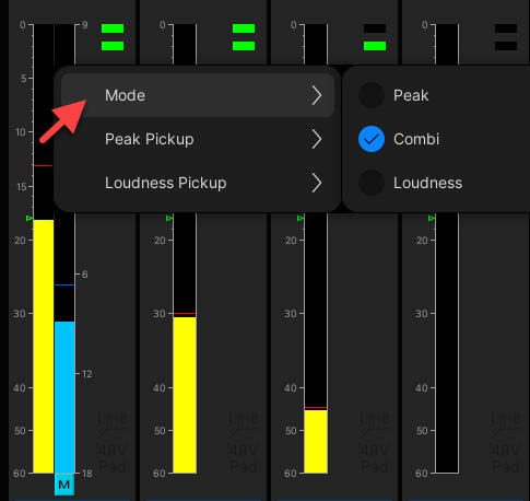
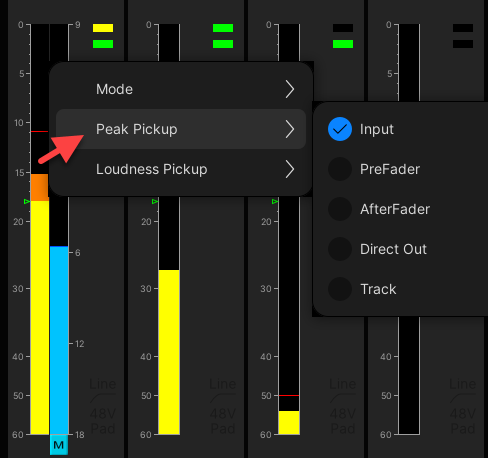
- Touch anywhere on the channel meter to open the pop-up.
- Choose Mode, Peak Pickup or Loudness Pickup.
- Choose an option from the drop-down menu.
Note that the pickup point can be different for the peak and loudness meters. If you change the pick-up point here, then this is reflected in the signal flow shown on the Channel Config display.
DSP Mini Display

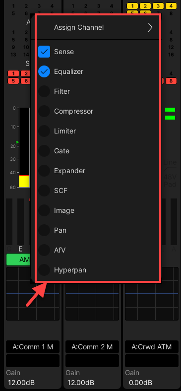
- Touch anywhere inside the mini display to open the pop-up.
- Choose either Sense or a specific DSP module (e.g. Equalizer).
If you choose Sense, then the mini display automatically updates when you touch a Free Control on the fader strip. Turn Sense off to permanently display a specific module.
Fader Strip Assign
The same pop-up can be used to assign a different channel to the fader strip. This provides an alternative to the Access/Assign method described later.
- Touch the current channel label (or mini display) to open the pop-up.
- Choose Assign Channel followed by a channel type and number. The selected channel is assigned, and the fader strip updates accordingly.

