mc²56 - The Signal List display
All signal routing is performed from the Signal List display. From here, you can:
- Connect a source to an input channel.
- Connect an output bus or channel send to a destination.
- Connect a source directly to a destination, bypassing the DSP.
From Version 10.0.2 onwards, the external signals which appear in the Signal List display are defined by HOME (Lawo's IP management tool). How to manage the I/O devices and setup the streams is described later. This topic assumes that the streaming configuration is complete, and that there are some external I/O signals available.
Operating Principles
The Signal List display is used for three main tasks: to make (and break) connections; edit signal labels and parameters; and define DSP channels for mono, stereo or surround.
- Press the SIGNAL button on the SCREEN CONTROL panel.
- Select Signals → Signal List from the GUI page menu.
- Press CTRL + 1 on the console keyboard.
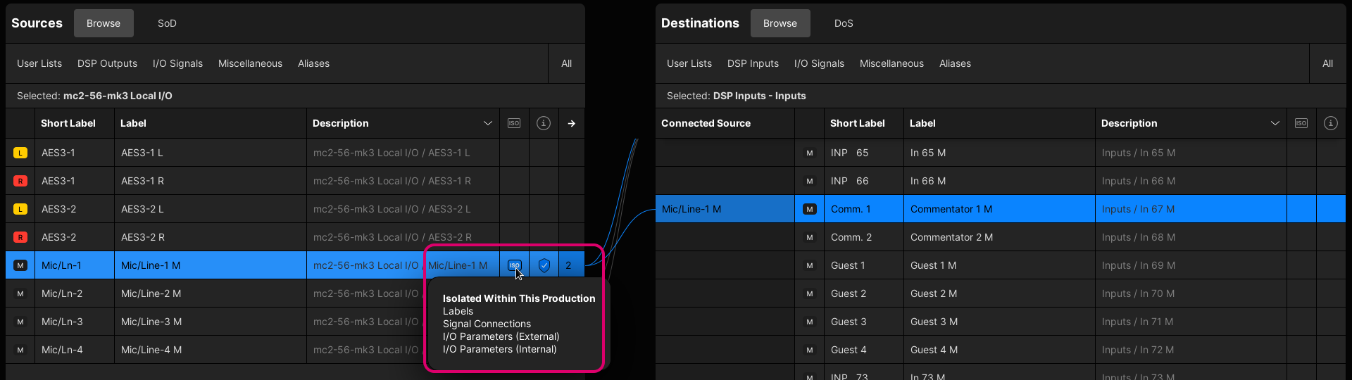
The display shows connections from Sources on the left to Destinations on the right.
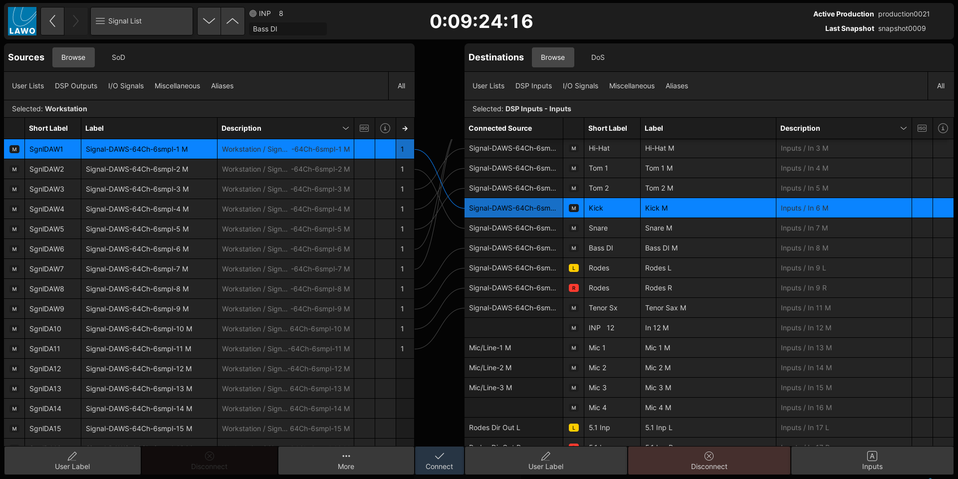
2. At the top of each list, there are two possible views: Browse (by directory) or show Source of Destination (SoD) / Destination of Source (DoS).
When Browse is selected, you can choose All (to view all of the system's signals), or filter the list by selecting a directory path.
There are five main directories, where the User Lists are optional and the other directories are system-defined: DSP Outputs (or DSP Inputs), I/O Signals, Miscellaneous and Aliases.
User Lists can be created to help organize signals at either a system or production level. For example, a mic/line input from an A__stage device will always appear in the I/O Signals directory (under the I/O device's name), but may also appear in a "System List" named Stagebox A and in a "Production List" named Show 1 Mics.
The Signal List Directories and User Lists are described in more detail later. For now, under Destinations, select DSP Inputs and Inputs (to view all of the console's input channels). The full path (DSP Inputs → Inputs) appears in the Selected directory field.
3. To navigate each list, you can scroll up and down in the following ways:
- Use the on-screen vertical scroll bars (on the right of each list). The scroll bars are hidden from view and appear automatically (as required).
- Press the console keyboard up/down keys.
- Press SCREEN CONTROL panel up/down keys.
- Turn the rotary control on the SCREEN CONTROL panel.
You can also sort a list alphabetically by selecting one of the column headers (e.g. "Label").
4. In the standard view (shown above), all signals are listed as mono resources.
The format column shows whether a signal is mono (M) or linked for stereo or surround (L, R, C, etc). The color-coding makes it easy to spot the stereo and surround component channels.
If you are handling lots of stereo or surround signals, then you may prefer to work in Signal Mode (as this condenses the view by grouping the linked signals).
In each case, the format of the DSP channels can be changed using the Stereo or Surround options in the right-click context menu. For more information, see Create Stereo and Surround Channels.
5. If a destination is connected, then the source label appears in the Connected Source column.
If the source is also in view, then a solid line appears showing the connection.
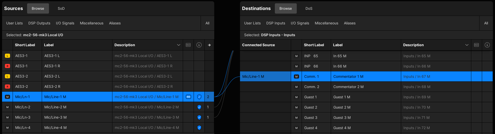
6. To make a connection, select a source (on the left) and a destination (on the right); then click on Connect.
- A dotted (preview) line appears when a connection is prepared.
- This changes to a solid line once the source(s) and destination(s) are connected.
- Once a valid source is connected, the Connected Source field updates.
- You can select multiple sources and/or destinations by clicking and dragging, or using SHIFT or CTRL on the console keyboard. This allows you to connect or disconnect multiple signals in one operation.
- Optionally, you can enable Step Connect Mode (from the More... options). This can be used to connect (or disconnect) consecutive sources and destinations by repeatedly pressing Connect (or Disconnect).
For more information, see Signal Connections.
7. At the bottom of each list, the User Label button opens the label editor for the selected source or destination.
For each signal, there are two label fields: the full User Label (shown in the GUI displays) and the Short User Label (shown on the surface displays). How to use the label editor is described in User Labels.
8. On the Sources side, the More... button reveals a number of additional options.
These can be used to access other signal-related functions or customize the view. All possible options are described here.
9. On the Destinations side, the Inputs A (or Inputs B/Inputs C) button allows up to three sources to be assigned to each input channel (as main and alternate sources).
How to assign and use the alternate inputs is described in Source Routing. For now, make sure that Inputs A is selected so that you are working on the main source for the channels.
10. Finally, if you select a source (or destination) and right-click, then a context menu appears.
This provides access to the signal-related options (for the selected source or destination). The image below shows an example for a mic/line (source) and DSP channel (destination).
If more than one source (or destination) is selected, or if an option is not relevant, then only the applicable options are shown (to simplify the view).
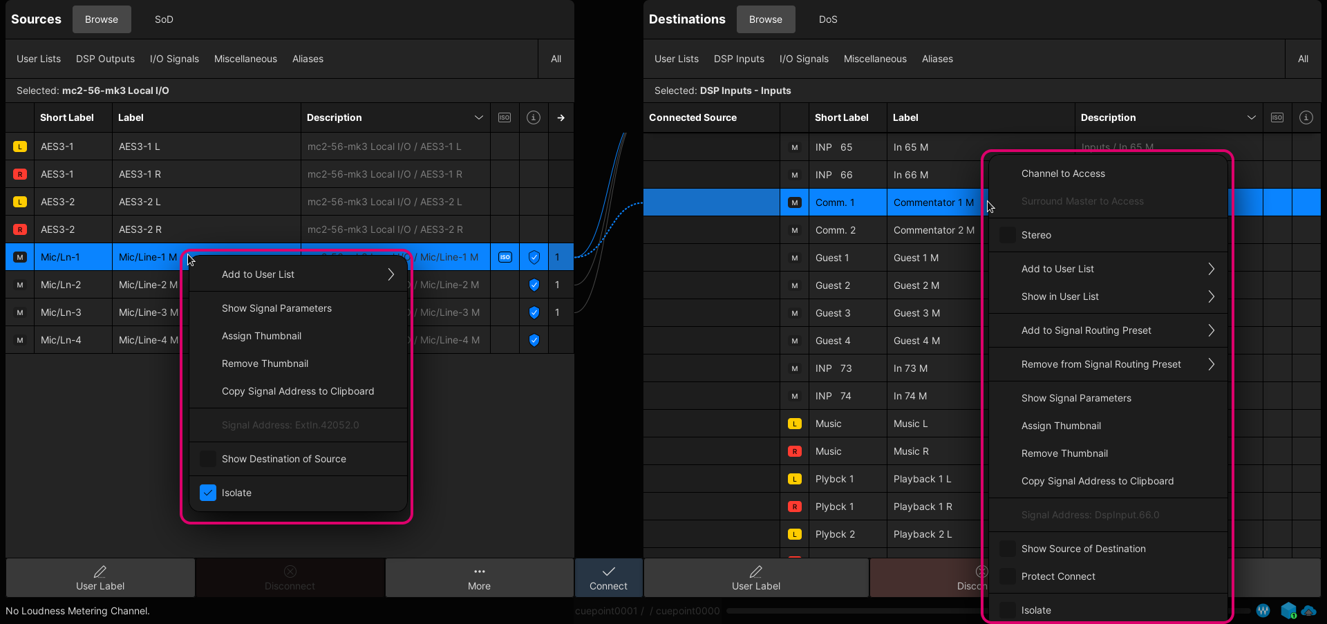
All possible options are as follows:
- Channel to Access (DSP channels only) - puts the selected channel into access.
- Surround Master to Access (Surround DSP channels only) - puts the channel's Surround VCA master into access.
- Stereo (DSP channels only) - links odd/even channels for stereo.
- Surround (DSP channels only) - links a range of channels for surround; the format is selected from the drop-down menu.
- Add to User List - adds the signal to an existing or new user list. See User Lists.
- Remove from User List (appears if a user list is in view) - removes the signal from the user list.
- Show in User List - shows where the signal is used. From here, you can click on the user list name to bring it into view.
- Add to Signal Routing Preset (Destinations only) - adds the selected connection(s) to an existing or new signal routing preset. See Signal Routing Presets.
- Remove from Signal Routing Preset (Destinations only) - removes the selected connection(s) from an existing signal routing preset.
- Show Signal Parameters - opens the signal parameter window.
- Assign Thumbnail - opens the 'Signal Thumbnail' assignment window (to assign a LiveView image). See User Labels.
- Remove Thumbnail - removes the existing thumbnail assignment.
- Copy Signal Address to Clipboard - copies the signal address (e.g. to paste into a Custom Function).
- Signal Address (read-only) - shows the signal address (for information only).
- Show Source of Destination (SoD) or Show Destination of Source (DoS) - interrogates the connections to or from the current selection. See Interrogate Signal Routing.
- Protect Connect (destinations only) - protects a destination so that no changes to its connection can be made. See Protect Connect.
- Isolate - isolates the signal from a snapshot load. See Signal Isolate.
Columns, Icons & Tooltips
The columns in the source and destination lists provide the following information:
- Format - this column shows the format of the signal: M (mono), L (left), R (right), C (centre), etc. The icons are color-coded for easy identification.
- Short Label & Label - these columns show the user labels for the signal. They can be edited by pressing the User Label button (to open the label editor).
- Description - this column describes the origin of the source or destination using its device name and signal type/number. The description cannot be edited from the Signal List, but is affected by the labels defined in HOME. An example is provided here.
- ISO - this column shows whether a signal is isolated from snapshot loads. A blue ISO icon appears if Isolate is enabled.
- i (info) - this column provides information about the signal through a series of icons (that are described below).
- → (Sources only) - this column indicates the number of times a source is used. i.e. the number of connections made. You can interrogate the connections using DoS (Destination of Source).
- Connected Source (Destinations only) - this column shows the full user label of the connected source. If the connection is protected using Protect Connect, then a yellow padlock icon appears.
Please note: The Label and Description columns can be hidden (to streamline the view). This is done by turning off Show User Label Column and/or Show Description Column (in the More... options menu).
Info Icons
The following icons can appear in the i (info) column. The signal error icon takes priority (and overrides all other active states).
| Icon | Meaning | |
|---|---|---|
| Signal Ownership | The signal belongs to an ownership group. |
| Signal Function: Alias | The signal is an alias input or output. |
| Signal Function: Waves | The signal is a Waves input or output. |
| Signal Function: Loopback | The signal is a virtual Loopback. |
| Signal Error | The signal is not available.
|
Signal Tooltips
Whenever you hover over a source or destination, its label appears in a tooltip. This confirms what will be selected (before the selection is made).
Please note: The signal label tooltips can be disabled by turning off Show Signal Tooltip (in the More... options menu). This option does not affect other tooltips such as the Connected Source field or ISO icon tooltips (described below).
Info Tooltips
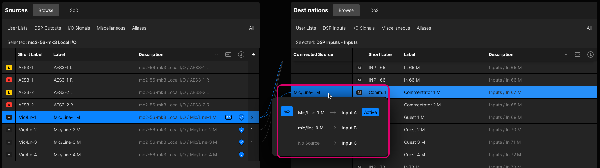
There are various other tooltips that appear whenever you hover over a field. These provide important information and always enabled. Two useful examples are the tooltips for the Connected Source and ISO icon.
If you hover over the Connected Source field, then the tooltip shows information about the connected source. For example, for a DSP input: whether the A, B and/or C inputs are connected and which input is currently active.
If you hover over an ISO icon, then the tooltip serves as a reminder of what is isolated. i.e. the signal Labels, Connections and I/O Parameters with the current production.
More... Options
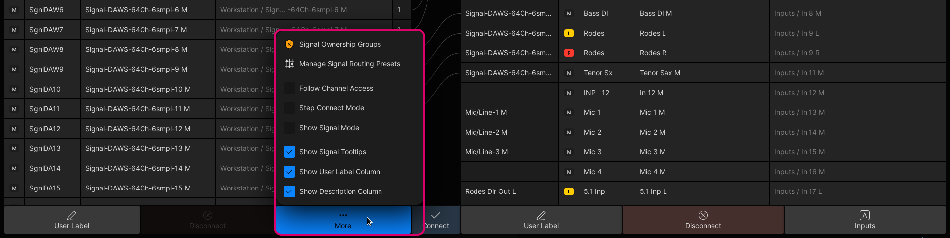
The More... button provides access to the remaining Signal List options.
Signal Ownership Groups
Opens the management window for the Signal Ownership Groups.
From here, you can see which signals belong to an ownership group, and either take or release the ownership.
For more information, see Signal Ownership Groups.
Manage Signal Routing Presets
Opens the management window for the Signal Routing Presets.
From here, you can perform the following operations:
- New - creates a new (empty) preset. You are asked to enter a Label.
To add connections to the preset: select one ore more destination(s), right-click and choose Add to Signal Routing Preset from the context menu. - Label - edits the label of the selected preset.
- Delete - deletes the selected preset.
- Load - loads the selected preset.
If the destinations are in view, then you will see the Connected Source fields update.
For more information, see Signal Routing Presets.
Follow Channel Access
When Follow Channel Access is enabled, the selected signal (in the Signal List) follows the channel in access. This means, for example, when you press a fader SEL (on the surface), the DSP channel is automatically selected (in the Signal List).
Please note: This option changes the selected source or destination whenever you change the channel in access. For this reason, the option is usually disabled.
It can be useful during a live production to quickly focus on the selected channel.
Step Connect Mode
When Step Connect Mode is enabled, the system automatically selects the next source and destination (in the signal lists) after each press of Connect or Disconnect.
This can be used to quickly connect (or disconnect) consecutive sources to consecutive destinations by repeatedly pressing Connect (or Disconnect).
For more information, see Step Connect.
Show Signal Mode
This option changes how the signals are displayed in the Source and Destination lists.
When Show Signal Mode is disabled, all signals are shown as mono resources. This is the default (standard) Lawo view, where you can see and connect each mono resource independently. It means, for example, that the left and right inputs of a stereo channel are always visible without needing to reveal the components.
When Show Signal Mode is enabled, all signals are grouped according to their format: as mono, stereo or surround signals. This results in a more condensed view if you are handling lots of stereo or surround signals. It provides the same functionality as the standard view, but requires an additional click if you need to reveal the grouped components.
For more information, see Signal Mode.
Show Signal Tooltips
This option can be used to show (or hide) the signal tooltips (that appear when you hover over the full Label of a source or destination).
Please note: This option does not affect other tooltips such as the Input A/B/C tooltip that appears when you hover over the Connected Source of a DSP channel.
Show User Label & Show Description Column
The last two options can be used to show (or hide) the full user Label and/or Description columns (to streamline the view).
FAQs
The rest of this topic answers some of the most frequently asked questions about the Signal List display.
Why are my signals missing?
If your external I/O device is missing from the signal lists, then you should check the device and its streaming configuration (in HOME).
- The device must be known to HOME and have some IP senders and receivers (to carry the audio I/O signals).
- The device's IP senders and receivers must be connected to the mc2 DSP. In a A__UHD Core system, this is done by connecting the I/O device senders (and receivers) to the receivers (and senders) of a Virtual Mixer.
- Once the correct stream routing is configured, the mc2 signal list automatically updates.
For more information, please see Device Management (using HOME).
Can I make connections if my I/O device is offline?
Yes.
Once a device's signals have been added to the mc2 signal list, then they will remain there (even if the device goes offline). This can be used, for example, to prepare connections to and from a remote Stagebox before it is powered/connected.
In this instance, you will see the Signal Error icon (in the info column) to show that the signals are not available. Once the Stagebox is powered and connected to the network, its streaming configuration will be re-instated, and the Signal Error icons disappear.
What do the dotted (preview) lines mean?
A dotted (preview) line appears when a connection is prepared but not made. You can use this to check the outcome before selecting Connect.
What do the icons mean?
The icons in the "info" column are described here.
You may also see the signal function icons in the Connected Source field (once a connection is made).
If a matrix crosspoint is protected, using Protect Connect, then this field displays a yellow padlock icon.
Where are my settings saved?
All of the following settings (in the Signal List) are saved in snapshots and productions: signal connections, user labels and signal parameters.
Other settings, such as the Signal Routing Presets and More... option states, are saved in productions (but not in snapshots).
If you want to protect a destination crosspoint on a more comprehensive level, then a Protect Connect can be applied.
For more information, see Signal Isolate & Protect Connect.