mc²56 - Configure I/O Device (in HOME)
The signals which appear in the Signal List are defined by an IP management tool known as HOME.
HOME defines all of the network routing for management and streaming. Thus, it is responsible for configuring the sending and receiving streams between an I/O device and the A__UHD Core Virtual Mixer.
If an I/O device is not configured in HOME, then its signals will not appear in the mc2 Signal List display. This topic describes what to do when a new I/O device is installed.
The configuration is done in four stages:
- Step 1 – Check the Device is known to HOME
- Step 2 – Label the Device (in the Devices page).
- Step 3 – Set up the Streams between the I/O Device and A__UHD Core Virtual Mixer
- Step 4 – Save the Streaming Configuration
Once the streaming configuration is saved, it is loaded (by HOME) after every restart. Thus, this is a one-time setup which you should not need to repeat.
The same workflow can be used for any of the following devices: Local I/O, Compact I/O and A__line.
For other devices, you can create a third party virtual device. An example is provided later.
Prerequisites
The I/O device must be correctly installed and connected to the network.
You can check this by opening a connection to HOME and checking the device status.
Opening HOME / Checking the Device Status
A connection to HOME can be opened from a service computer connected to the same Management Network as the mc2 control system. To run the Web UI, your computer MUST meet or exceed the following requirements:
- Processor: Pentium 166 or higher
- RAM: 64 MB
- Network Interface Card: operating at 100 or 1000 Base-T
- Screen Resolution: >= 1024 x 786
- Web Browser: Microsoft Internet Explorer, Mozilla Firefox, Apple Safari or Google Chrome. Please install the latest version of the browser for best performance.
Opening the HOME Web UI
1. Connect your computer's LAN port to the Management Network.
2. Configure the network settings for your computer's Network Interface Card (NIC). The exact steps vary depending on your OS version.
The IP address must be unique, and set within the same range as that of the mc2 control system. Use the IP Address Primary field (in the System Settings page -> Global) to check the current mc2 system IP address.
The subnet masks should be identical (default subnet = 255.255.255.0).
A default gateway setting is required if data packets are to be redirected. For example, if you are connecting via a network switch with Layer 3 routing capability. If redirection is not required, then the default gateway can be left blank.
3. Open a web browser and enter the IP address of the mc2 system (default IP = 192.168.102.xxx).
If the connection is successful, the mc2 landing page appears.
If there is a problem opening the page, check the service computer requirements. Then check the network cabling and IP settings.
4. From the mc2 landing page, click on the top image to open the HOME Web UI.
The browser updates and you will see the HOME "Devices" page.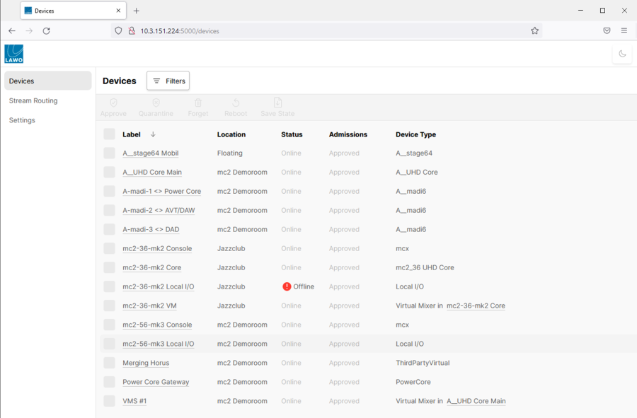
This page lists all of the devices known to HOME.
If your I/O device is correctly installed, powered and connected, then its Status will show as Online.
Note that all Lawo devices connected to the network are discovered automatically, and are assigned a default label such as mc2-56-mk3 Console, mc2-56-mk3 Local IO, etc.
A__UHD Core & Virtual Mixers
You will see at least two entries for the A__UHD Core: one for the general administration and one for each Virtual Mixer.
If there is more than one Virtual Mixer, then you can check which one is connected to your console as follows.
1. Click on the console label (e.g. mc2-56-mk3 Console) to open its "Device" information page.
2. At the top (under A__UHD Core Processing), you will see the label of the Virtual Mixer (e.g. VMix one).
If there is "no processing connected to the control surface", then you will need to connect the control surface to a Virtual Mixer. How to do this is described later.
Labeling the Device
At this stage, it is a good idea to edit the device label, as it will appear in the Signal List display once the streams are configured.
The device label (in HOME) is used in two places on the Signal List display: in the I/O Signals directory and in the signal Description field (Description field = Device Label / Physical IO Label).
The screenshots below show how this works.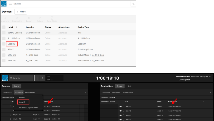
- To edit the device label
1. Open the "Devices" page and click on the current label (e.g. mc2-56-mk3 Local IO).
A page opens showing general information about the device.
2. Select the Edit button to open the "Edit Device Info" pop-up.
3. Enter the new label text into the "Full Label" field (e.g. Local IO).
You can also enter a "Location" (to help identify the device in HOME).
4. Select Done to confirm and close
The device label updates everywhere in HOME (and will be forwarded to the Signal List display when the streams are connected later).
The Identify Device Hardware button can be used to flash the NET ID LED on the physical unit. This makes it easy to identify the device you are about to configure. |
Setting up the Streams
Having labeled the I/O device, it is time to set up the streams. This is where most of the work takes place. The setup is done in four parts.
- Part 1 – Create the sender(s) and receiver(s) for the Virtual Mixer.
These can be given a generic name such as Rx1, Rx2 and so on (as the stream names only appear in HOME).
In the example which follows, we will create 2 x 64-channel Rx and Tx (to carry the 128 channels of the Local IO: Mic/Line, Line Out, AES3, Phones, RTW & MADI).
HOME does not care about the number of channels per stream, as long as there are enough channels on the sending and receiving side to make the Stream Routing connections. |
- Part 2 – Create the sender(s) and receiver(s) for the I/O device.
Again, these can be given a generic name or a more descriptive name depending on the network size.
Once the I/O Routing is assigned (in the next step), it is the physical I/O names which are passed through to the Signal List display (e.g. Local IO / mic-line n).
- Part 3 - Configure the I/O Routing (in the I/O device).
This part determines which sender and receiver channels are used for each physical I/O in the device (Mic/Line, Line out, AES3, etc.)
For our Local IO example, we will use Tx1/Rx1 for the miscellaneous I/O and Tx2/Rx2 for the 64-channel MADI.
- Part 4 - Connect the streams.
The final part is to connect the I/O device sending streams to the Virtual Mixer receivers, and vice versa.
As long as the number of channels on each side match (e.g. 64-channel sender to 64-channel receiver), the setup is complete and you will be able to access the signals from the mc2 Signal List.
------------------------------------------------------------------------------------------------------------------------------------
The rest of this section describes each part in more detail.
Part 1 - Creating the sender(s) and receiver(s) for the Virtual Mixer
1. Open the "Devices" page and click on the label for the A__UHD Core Virtual Mixer (e.g. VMix one).
Take care to select the Virtual Mixer and not the A__UHD Core. If you make a mistake and select the Core, then the Senders and Receivers tabs will be missing.
2. Select the Senders tab to view the list of senders.
In our example, nothing has been configured and so the list is empty. However, if you are adding a new device to an existing network, it is likely that there are already some senders (and receivers).
3. Select the New Sender button and follow the on-screen instructions to create the senders.
For our example, we will create two 64-channel senders.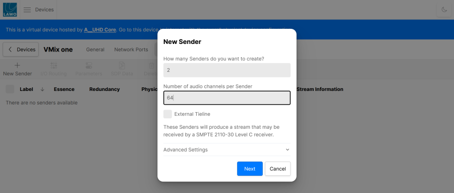
The External Tieline option should left as it is . It can be turned on to create an external tie-line sender (to publish audio to the network).
The Advanced Settings can be used to adjust advanced parameters for the stream (as described later). In most instances, it is fine to use the default values and there is no need to adjust these parameters at this stage.
4. Select Next to continue and enter a label for the first sender (e.g. Tx1).
The label fields auto-complete as you enter your text.
If the label ends in a number, then this will increment.
If you use double braces, then you can enter an auto-incrementing range. For example, when creating 8-channel streams. you could type Tx 1-8 to enter the sender labels: Tx 1-8, Tx 9-16, Tx 17-24, etc.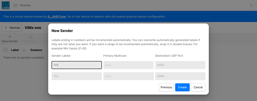
For each sender, the Primary Multicast and Destination UDP Port fields determine how the multicast addresses will be created. There are two possibilities: either automatic or manual.
If you leave the fields at their default values (auto and 5004), then the stream will be allocated an automatic multicast IP address and port. In most instances, this is fine.
To assign a multicast IP address and port manually, type the values into the corresponding input fields. Use this method if your network supports a limited IP range.
5. Select Create to create the streams.
The sending streams are added to the list of Senders. The final result looks like this.
6. Next, select the Receivers tab and use the New Receiver button to create the receiving streams.
The method is the same as for the Senders. For our example, we will create two 64-channel receivers using the labels Rx1 and Rx2. The final result looks like this.
Note that the warning indicator in the Status column is normal at this stage, as the receiver has nothing to subscribe to until it is connected (in the Stream Routing page).
Part 2 - Creating the sender(s) and receiver(s) for the I/O device
In this part, we will create the senders and receivers for the I/O Device. The steps are identical to those described earlier for the Virtual Mixer, but this time the work is done in the I/O device page.
1. Open the "Devices" page and click on the label for the I/O device (e.g. Local IO).
2. Select the Senders tab and use the New Sender button to create the sending streams.
3. Then select the Receivers tab and use the New Receiver button to create the receivers.
To create 2 x 64-channel sending and receiving streams, the steps look like this.
Local IO -> Senders -> New Sender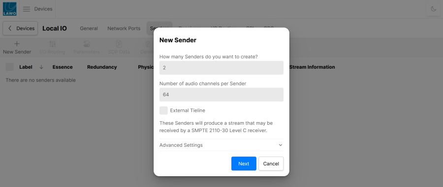
New Sender (Enter Labels)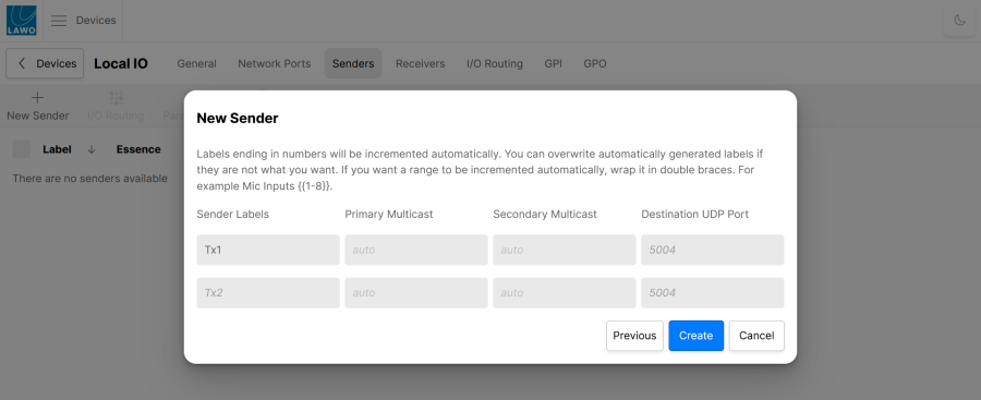
The final results looks like this.
Local IO (Senders)
Local IO (Receivers)
Remember that the warning indicator in the Status column is normal at this stage. It will disappear once the receiver is connected in the Stream Routing page.
Part 3 - Configuring the I/O Routing (in the I/O device)
In this part, we will connect the IP channels (of the senders and receivers) to the physical I/Os of the device.
Note that HOME does not care which streaming channels are used, but it is important to make one-to-one assignments (and not one-to-many or many-to-one, as this can lead to confusing results).
1. Open the "Devices" page and click on the label for the I/O device (e.g. Local IO).
2. Select the I/O Routing tab to open the device's internal routing page.
The operation is very similar to the Signal List display with Sources (on the left) and Destinations (on the right). When you first open the page, you will see all sources and all destinations.
3. It is a good idea to use the Filters to restrict the view.
This can be done by entering a text string, or using the Filter by type option.
- Beside Sources, select the Filters button and choose Filter by type.
- Select the sources you wish to view (e.g. AES3 and MIC/LINE).
I/O Routing: Sources (filtered by type)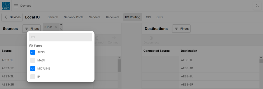
- Click anywhere outside of the Filters box - the pop-up closes and the filters are applied.
- Repeat to filter the Destinations, but this time choose IP.
I/O Routing: Destinations (filtered by type)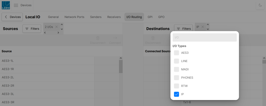
You should now see all of the physical I/Os (on the left) and IP channels (on the right). Thus, the view is prepared for the next step.
4. Connections are made in the same way as on the Signal List.
- Select a source and a destination. Then press Connect - the dotted (preview) line changes to a solid line and the "Connected Source" field updates.
- To make multiple connections, press and hold SHIFT or CTRL to select multiple sources and destinations.
- To remove a route, select the destination(s) and press Disconnect.
I/O Routing: physical I/Os -> Tx channels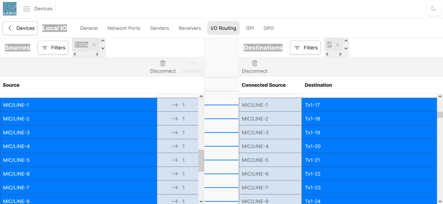
5. Once you have connected all of the physical I/Os to the sender's channels, reverse the Filters, and connect the receiver's channels to the physical I/Os.
When the I/O routing is complete, each physical I/O should be connected once. You can look at the "source used" count to check this.
For our example, using a Local I/O, the following connections must be made:
- AES3 1-8 -> Tx1 1-16
- MIC/LINE 1-16 -> Tx1 17-32
- MADI 1-64 -> Tx2 1-64
- Rx1 1-16 -> AES3 1-8
- Rx1 17-32 -> LINE 1-16
- Rx1 33-36 -> PHONES 1-4
- Rx1 37-44 -> RTW 1-8
- Rx2 1-64 -> MADI 1-64
Part 4 - Connecting the Streams
Having configured the senders, receivers and I/O routing, the last step is to connect the streams.
1. Open the Stream Routing page to view all of the existing connections.
The operation is identical to the I/O Routing page, except that connections are made at a stream level (instead of a signal level).
2. Streams are connected and disconnected in the usual manner.
Select a source and a destination stream. Then press Connect - the "stream used" count (beside the source) and "Connected Source" field (beside the destination) update.
Stream Routing: Local IO sender -> Virtual Mixer receiver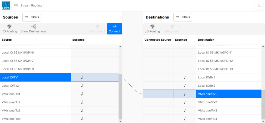
Stream Routing: Virtual Mixer sender -> Local IO receiver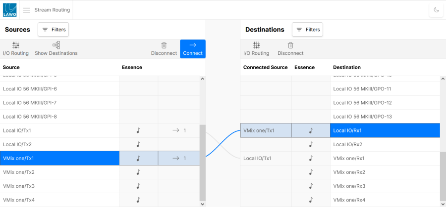
For our example, using the Local IO, there are four connections to make:
- Local IO Tx1 -> VMix one Rx1
- Local IO Tx2 -> VMix one Rx2
- VMix one Tx1 -> Local IO Rx1
- VMix one Tx2 -> Local IO Rx2
3. Now move over to the console, and open the Signal List display (on the Central GUI).
You should see your new device signals on both sides of the list.
If they do not appear automatically, then select Refresh I/O Signals Menu to update the list.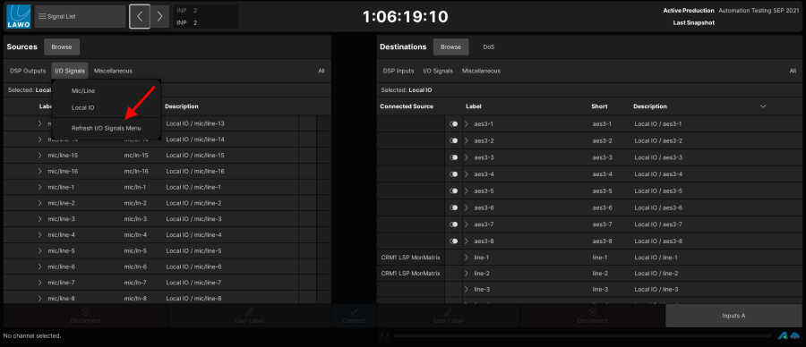
The streaming configuration is now complete and you should be able to connect signals to and from the your new IO device and pass audio!
To save the changes to the streaming configuration, you must continue on to the next step. If you forget to save manually, then the changes will be lost after the next reboot. |
Saving the Streaming Configuration
The final step is to save the changes to the streaming configuration. This will ensure that everything comes back after a system restart.
1. Open the "Devices" page and click on the label for the I/O device (e.g. Local IO).
Under the General tab, you will see the button called Save State.
2. Click on Save State to save all of the changes made (for this device).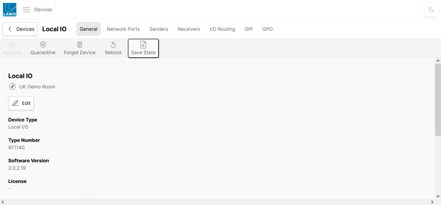
You can confirm the save by looking at the Last Save Date field (towards the bottom of the page).
3. Return to the "Devices" list and this time select the label for the Virtual Mixer (e.g. VMix one).
4. Click on Save State to save all of the changes made (for the Virtual Mixer).
And check the Last Save Date field to confirm the save.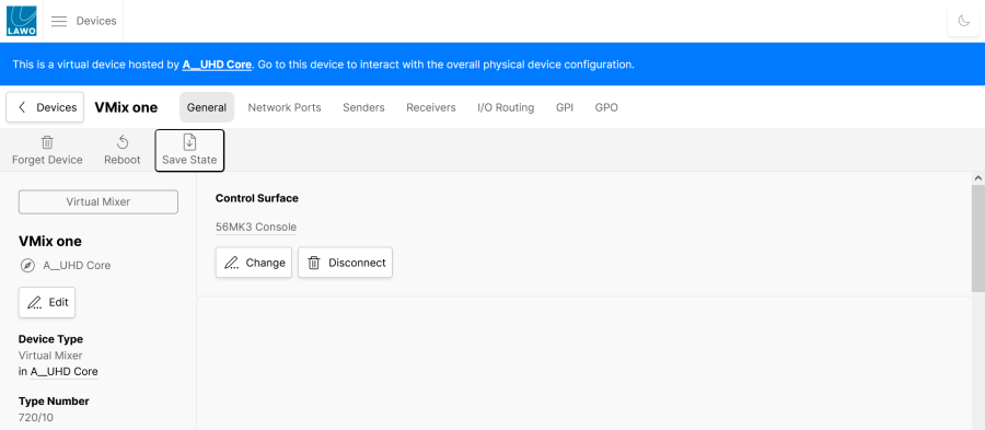
All of the tasks for your new I/O device are now complete.