Power Core - Controls, Connectors and Indicators
This topic describes the controls, connectors and indicators of the current hardware revisions. Note that the front panel controls differ slightly, while the rear panel is the same for both revisions.
For more information about the connectors and cabling requirements, see Power Core - Wiring.
Controls Overview
The controls are divided into the following areas.
Front View, Revision 3
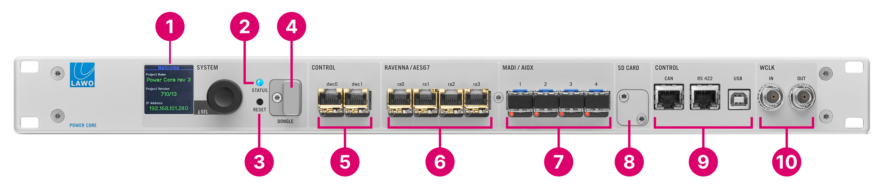
1. SYSTEM Display & Menu Control
2. STATUS LED
3. RESET button
Front View, Revision 2
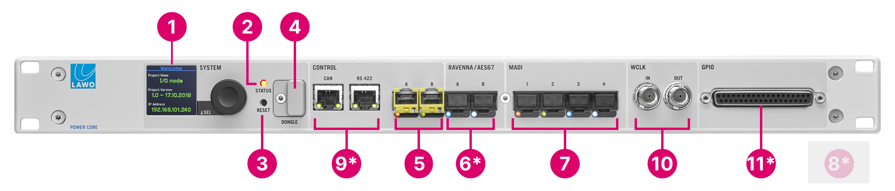
For Power Core revision 2, the asterisks (*) indicate a difference in functionality from a revision 3 frame: fewer RAVENNA/AES67 ports (6); no access to SD card (8); no USB port (9); GPIOs are included (11). All other controls work in an identical manner, with some variations in the connector labelling.
1 to 10. as described above.
11. GPIO
The table below compares the current hardware revisions; all differences are highlighted in bold.
| Revision 3 | Revision 2 | Notes | ||
|---|---|---|---|---|
| 1. | SYSTEM Display & Menu Control | yes | yes | |
| 2. | STATUS LED | yes | yes | |
| 3. | RESET button | yes | yes | |
| 4. | DONGLE port | yes | yes | |
| 5. | CONTROL Network Ports | 2 | 2 | dwc0 = CONTROL A; |
| 6. | RAVENNA/AES67 Network Ports | 4 | 2 | ra0 = RAVENNA A; ra1 = RAVENNA B |
| 7. | MADI/AIOX Ports | 4 | 4 | |
| 8. | Front panel access to SD card | yes | no, access is internal | |
| 9. | USB service port | yes | no, use RS-422 port | |
| 10. | WCLK IN & OUT | yes | yes | |
| 11. | Front panel GPIO | no | yes | GPIO can be added via the rear expansion I/O |
Rear View, all revisions
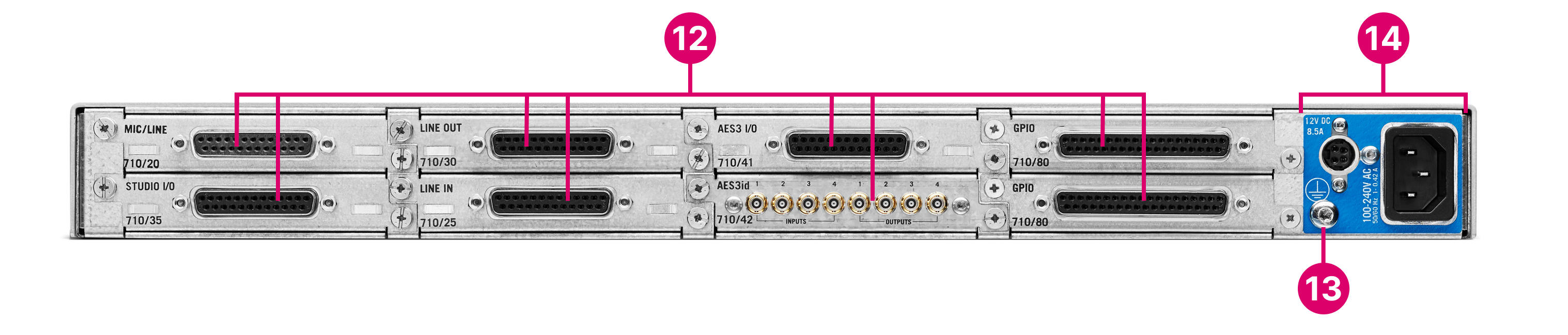
13. Functional Earth
Front Panel
SYSTEM Display & Menu Control
The front panel display and rotary encoder can be used to view or edit device parameters such as the IP address.
For more information, see Power Core - SYSTEM Display.
STATUS LED
The STATUS LED indicates the health of the device and sync status.
- If the LED is blinking at regular intervals, then the device is working properly and the LED color indicates the sync source/status.
- If the LED is lit and static, then either the device is booting or there is an internal problem.
The tables below describe all possible meanings.
| Blinking STATUS LED | Meaning |
|---|---|
| Blue ↔ Off | Synchronized to PTP master |
| Yellow ↔ Off | Trying to sync to PTP master |
| Red ↔ Off | Synchronized to internal clock |
| Green ↔ Off | Synchronized via Wordclock |
| Magenta ↔ Off | Synchronized via MADI |
| Red ↔ white | Device is PTP Master, sync source = internal |
| Green ↔ white | Device is PTP Master, sync source = Wordclock |
| Magenta ↔ white | Device is PTP Master, sync source = MADI |
| Static STATUS LED | Meaning |
|---|---|
| Off | System powered off |
White | System starting |
Color (not white) | System failure |
RESET button
The RESET button can be used to reboot the device and load the warm start data. The button is recessed to prevent accidental operation.
This operation should NOT be performed while the device is live on-air!
License DONGLE
The DONGLE port should be used to connect the USB memory stick containing your system's WIBU license(s). A safety cap is available to prevent accidental removal of the dongle. If fitted, you will need a T10 star tool to remove the cap.
CONTROL Network Ports
The dwc0 and dwc1 network ports are used for administration and control. On Power Core revision 2, the ports are labelled A (dwc0) and B (dwc1).
Applications include remote control via TCP/IP; networking to other products; updating firmware and uploading a configuration.
Usually, only the first port (dwc0) is connected. It is possible to configure dwc0 and dwc1 as redundant interfaces using either a LACP bond or generic failover mode using the Power Core web UI.
The control network must be separate from the streaming network connected to the RAVENNA/AES67 ports (6).
RAVENNA/AES67 Network Ports
The RAVENNA/AES67 interfaces can be used to stream audio to and from the IP network.
- On Power Core revision 3, there are up to four interfaces: ra0, ra1, ra2 and ra3. The first pair of interfaces are enabled as standard. The second pair of interfaces can be enabled by purchasing the optional AddOnRAV+ license.
- On Power Core revision 2, there are two interfaces: A and B. These are enabled as standard.
The streams are fully compatible with SMPTE ST2110-30/31, AES67 and RAVENNA. To achieve redundant streaming, compatible with SMPTE ST2022-7, you must use both interfaces: ra0/ra1 (or ra2/ra3).
The streaming network must be properly managed and configured.
MADI/AIOX Ports
The four MADI ports can be used to connect multi-channel digital audio to the device (up to 64 bi-directional MADI channels per port). Ports 1&2 and 3&4 can be dual-redundant (defined by the ON-AIR Designer).
Alternatively, the ports can be used to connect a Power Core Audio I/O Extender (mounted externally) for additional I/O expansion.
System Data (SD) Card
The SD card stores all of the system software and configuration data.
On Power Core revision 3, the SD card can be accessed by removing the safety cover (included). This can be used to exchange the card (if you are replacing the hardware) or to remove and copy the card (to create a backup of the system data).
On Power Core revision 2, the SD card is internal.
Other CONTROL Ports
Power Core revision 3 supports three other control data ports.
- CAN - this port can be used to connect local CAN bus devices such as a ruby control surface or KSC/GPIO panel.
- RS-422 - the serial port can be used for remote control (e.g. of a playout system) or MACKIE HUI interfacing to a Digital Audio Workstation.
- USB - the USB port can be used for debugging.
On Power Core revision 2, there are two other control data ports: CAN and RS-422.
- The CAN port can be used as described above.
- The serial RS-422 port can be used as described above AND also for debugging.
- There is no separate USB port (for debugging).
Wordclock (WCLK) IN & OUT
The two WCLK connectors can be used for external synchronization.
If Ravenna streams are being used, then Power Core must either be synchronized to PTP arriving from the streaming network OR configured as a PTP Master.
If Power Core is a PTP Slave:
- WCLK IN is not used.
- WCLK OUT provides an output of the current system reference. It can be used to distribute a wordclock signal to non-PTP devices.
If Power Core is a PTP master:
- WCLK IN can be connected to provide an external sync reference.
- WCLK OUT provides an output of the current system reference. It can be used to distribute a wordclock signal to non-PTP devices.
The WCLK OUT does not function while Power Core is being rebooted.
GPIO
On Power Core revision 2, there is a front panel GPIO connector. This provides 8 x GPI (optocouplers) and 8 x GPO (silent and self-healing relays) for local signalling and switched functions.
On Power Core revision 3, GPIOs can be added via the rear expansion I/O.
Depending on your main license package, you may need to purchase the GPIO add-on license to activate these signals.
Rear Panel
Expansion I/O Cards
Up to 8 expansion I/O cards can be fitted to the slots at the rear of the frame. All cards are hot-pluggable. Options include: Mic/Line In, Line Out, Studio I/O, AES3 I/O, Dante, MADI, MADI SRC, and GPIO.
Functional Earth
The CASE screw is used to ground the frame.
Please see Power Core - Grounding.
Power Inputs: AC & DC
Power Core comes with dual power feeds: AC and DC. To use the DC input, you will need the external DC power supply which must be ordered separately. If both inputs are connected, then the two feeds provide main and redundant power.
Please see Power Core - Power Supplies.